Sélection de la langue

Search

Sommaire du brevet 2058865 

Énoncé de désistement de responsabilité concernant l'information provenant de tiers

Une partie des informations de ce site Web a été fournie par des sources externes. Le gouvernement du Canada n'assume aucune responsabilité concernant la précision, l'actualité ou la fiabilité des informations fournies par les sources externes. Les utilisateurs qui désirent employer cette information devraient consulter directement la source des informations. Le contenu fourni par les sources externes n'est pas assujetti aux exigences sur les langues officielles, la protection des renseignements personnels et l'accessibilité.

Disponibilité de l'Abrégé et des Revendications

L'apparition de différences dans le texte et l'image des Revendications et de l'Abrégé dépend du moment auquel le document est publié. Les textes des Revendications et de l'Abrégé sont affichés :

  • lorsque la demande peut être examinée par le public;
  • lorsque le brevet est émis (délivrance).
(12) Brevet: (11) CA 2058865
(54) Titre français: PROCEDE ET JET D'EXPULSION DE L'AIR SECONDAIRE
(54) Titre anglais: PROCESS AND A JET FOR DELIVERING SECONDARY AIR
Statut: Périmé et au-delà du délai pour l’annulation
Données bibliographiques
(51) Classification internationale des brevets (CIB):
  • F23L 9/00 (2006.01)
  • F23L 9/02 (2006.01)
(72) Inventeurs :
  • MARTIN, WALTER JOSEF (Allemagne)
  • MARTIN, JOHANNES JOSEF EDMUND (Allemagne)
(73) Titulaires :
  • MARTIN GMBH FUR UMWELT-UND ENERGIETECHNIK
(71) Demandeurs :
  • MARTIN GMBH FUR UMWELT-UND ENERGIETECHNIK (Allemagne)
(74) Agent: SMART & BIGGAR LP
(74) Co-agent:
(45) Délivré: 1995-09-26
(22) Date de dépôt: 1992-01-07
(41) Mise à la disponibilité du public: 1992-07-25
Requête d'examen: 1992-05-25
Licence disponible: S.O.
Cédé au domaine public: S.O.
(25) Langue des documents déposés: Anglais

Traité de coopération en matière de brevets (PCT): Non

(30) Données de priorité de la demande:
Numéro de la demande Pays / territoire Date
P 41 02 072.3 (Allemagne) 1991-01-24

Abrégés

Abrégé anglais


The secondary air jets (11) that are arranged within the
combustion space (5) consist of an outer casing (12), an inner
casing (13), and a flange (14) that connects the two casings to
each other, the flange (14) crossing the inner casing (13) and
being rigidly connected with this, whereas the outer casing (12)
is so connected to the flange that is of greater diameter than
the outer casing (12) that slot-type jets (15) are left between
the face side of the outer casing (12) and the flange (14), these
jets making it possible to expel air parallel to the defining
wall and essentially perpendicular to the axis of the jets.

Revendications

Note : Les revendications sont présentées dans la langue officielle dans laquelle elles ont été soumises.


THE EMBODIMENTS OF THE INVENTION IN WHICH AN EXCLUSIVE
PROPERTY OR PRIVILEGE IS CLAIMED ARE DEFINED AS FOLLOWS:
1. A process for supplying secondary air to a furnace with
a mechanical fire grate, through which primary air is introduced,
and a combustion space that is arranged over this and defined by
walls, into which secondary air is injected by means of jets that
are arranged at least in the front and rear defining walls,
characterized in that on at least one defining wall which is in
the area that is acted upon by an opposig secondary air feed, the
secondary air is divided so that one part is directed into the
combustion space and a second part is directed parallel to the
defining wall.
2. A jet for carrying out the process as defined in claim
1, characterized in that it incorporates an outer casing that
tapers conically in the direction of flow, a cylindrical inner
casing, and a flange that holds the two casings concentrically
relative to each other and connects them rigidly together, the
flange crossing the inner casing and being of a diameter that is
greater than the diameter of the outer casing at the end of said
casing that is closest to the flange; and in that the outer casing
is secured at its face to the flange, and at least one section of
its periphery is configured as a slot-type jet between the outer
casing and the flange.
3. A jet as defined in claim 2, characterized in that in
the case of a plurality of slot-type jets these are configured so

as to be opposite each other and, in the case of only two jets,
they are arranged in the upper and lower sections of the periphery
of the outer casing.
4. A jet as defined in claim 2 or claim 3, characterized in
that the inner casing is shorter than the outer casing and is of a
length that is between three and six times its diameter.
5. A jet as defined in claim 2 or claim 3, characterized in
that the end of the inner casing that is located within the outer
casing is configured as a knife edge, with an inside diameter that
grows wider towards the outside and with a constant outside
diameter.
6. A jet as defined in claim 2 or claim 3, characterized in
that the inner casing is shorter than the outer casing and is of a
length that is between three and six times its diameter, and the
end of the inner casing that is located within the outer casing is
configured as a knife edge, with an inside diameter that grows
wider towards the outside and with a constant outside diameter.

Description

Note : Les descriptions sont présentées dans la langue officielle dans laquelle elles ont été soumises.

2058865
~rhe present invention relates to a process for introducing
secondary air into a furnace with a mechanical fire grate,
through which primary air is introduced, and above this, a
combustion space that is defined by side walls in which secondary
air is injected by means of jets that are arranged at least in
the front and rear defining walls. The present invention also
relates to a jet for carrying out this process.
In furnaces that incorporate the delivery of secondary air into
the combustion space by means of jets, when the jets are
preferably arranged on the front and rear walls, very frequently
particles of fuel are baked on in the area of one defining wall
that is located beneath an opposite secondary air jet, by which
they are thrown against the opposite wall, to which they adhere
because of the fact that these particles of fuel are still
incandescent and able to flow. Such encrustations can only be
removed with great difficulty and require that the whole furnace
be shut down, which is connected with a long period of downtime.
In the case of furnaces with a reversed feed grate, the
encrustations occur on the rear defining wall because its lower
wall area is exposed to the radiation effect of the secondary air
jet in the front defining wall because of the way the combustion
space is constructed.
It is the task of the present invention to prevent these
encrustations from forming on a defining wall or a plurality of
such walls of the combustion space.
/
~

2058865
25986-20
This task has been solved by the features of the present
lnventlon ln accordance wlth whlch there is provided a process for
supplylng secondary air to a furnace wlth a mechanlcal flre grate,
through which prlmary air is lntr-oduced, and a combustlon space
that ls arranged over thls and deflned by walls, lnto whlch
secondary alr is iniected by means of ~ets that are arranged at
least ln the front and rear deflnlng walls, characterlzed ln that
on at least one definlng wall whlch ls in the area that is acted
upon by an opposlng secondary alr feed, the secondary alr ls
divlded so that one part ls directed into the combustlon space and
a second part ls dlrected parallel to the deflnlng wall.
Because of the dlvlslon of the secondary alr lnto one
part that ls dlrected lnto the combustlon space and another part
that is parallel to the deflning wall, the latter forms a screen
on the deflnlng wall that ls able to trap some of the fuel
partlcles so that these cannot strlke the deflnlng wall. To the
extent that thls ls not posslble because the partlcles possess too
much klnetlc energy, the fuel partlcles wlll at least be cooled to
the polnt that they no longer adhere to the deflnlng wall. Thls
slmple measure thus serves to remedy a serlous problem that up to
now has had serlous consequences, as has been descrlbed
heretofore.
A ~et that ls used to carry out the process ls
characterlzed ln that lt lncorporates an outer caslng that tapers
conically ln the dlrectlon of flow, a cyllndrlcal lnner caslng,
and a flange that holds the two casings concentrlcally relatlve to
each other and connects them rlgldly to each other; thls flange

2058865
2a 25986-20
crosses the lnner casing and is of a diameter that extends beyond
the outer casing at its end that is proximate to the flange; and
in that the outer casing is secured at its face end to the flange;
and in that at least one area of the periphery is configured as a
face-end slot-type ~et between the outer casing and the flange.
As a result of this configuration, by using simple constructional

2058865
means, it is possible to achieve a purposeful and reliable
division of the secondary air into one part that is directed into
the combustion space and into a second part that extends parallel
to the defining wall as a screen.
In most applications, it is sufficient if, in the case of a
plurality of slot nozzles, these are formed opposite each other
and, in the case of only two nozzles, that these be located in
the upper and the lower sections of the periphery.
In order to ensure the reliable division of the secondary air
within the jet in such a manner that one part emerges into the
combustion space perpendicular to the defining wall and the other
part of the secondary air runs parallel to the defining walls, in
a further development of the present invention the inside casing
is shorter than the outside casing and is of a length that is
between three times and six times its diameter.
In order to effect the division of the secondary air within the
nozzle, as far as possible without any interference, in a further
configuration of the present invention the end of the inside
casing that is located within the outside casing is configured as
a knife edge, with an inside diameter that increases towards the
outside, and with a constant outside diameter.

2058865
i'he present invention will be described in greater detail below
on the basis of an embodiment shown in the drawings appended
hereto. These drawings show the following:
igure 1: a partial longitudinal section through the combustion
space of a furnace;
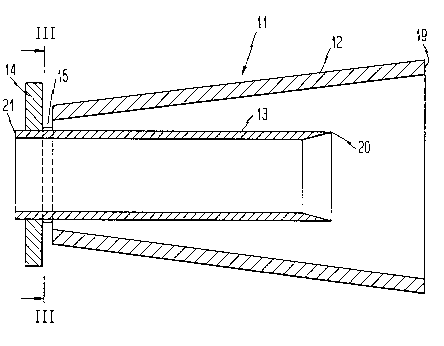
Figure 2: a longitudinal section through a first embodiment of a
secondary air jet;
Figure 3: a section on the line III-III in figure 2;
Figure 4: a longitudinal section through a second embodiment of a
secondary air jet;
Figure 5: a cross section on the line V-V in figure 4.
Figure 1 is a diagrammatic view of a section of a furnace that
incorporates a fire grate 1 and a feeding disk 2 with feed rams 3
that push the fuel that is delivered through the feed chute 4
onto the fire grate. The combustion space 5 that extends upwards
is formed above the fire grate, in its first section, and this is
defined by a front wall 6, a rear wall 7, and side walls 8.
Primary combustion air is fed to the fuel that lies on the grate
1 from below, through the grate. Because of the fact that
unburned particles are carried upwards by the rising gases, it is
preferred that there are secondary air nozzles 10 and 11
incorporated in the area of the front defining walls 6 and in the
area of the rear defining walls 7, and these inject additional
combustion air into the combustion space in order to subject the

2058865
unburned particles that rise upwards through the combustion space
to further combustion.
Because, in the past, it has been shown the unburned fuel that is
present in the rising gases is thrown against the rear defining
walls 7, where they wi]l adhere, because of the jets 10 that are
located in the area of the front defining wall, the secondary air
jets 11 in the rear ~fining wall are so configured that these
encrustations are pr~ ented by way of a special supply of air.
To this end, as is h~wn in figures 2 and 3, the secondary air
jet, consists of an outer casing 12 and an inner casing 13 that a
flange 14.crosses a~d to which it is rigidly connected, e.g., by
welding. At its f;.ce end, the outer casing 12 is connected to
the flange 14, th;s being done by interposing two arc-shaped
spacers 16 and 1/, which are rigidly connected on the one hand to
the flange 14 an(" on the other hand, to the face side of the
outer casing 12, which means that slot-shaped jets 15 are left
between the two spacers, between the face side of the outer case
12 and the flange 14, air being able to escape through these,
said air being supplied by means of a feed line (not shown
herein) that is conne-ted to the end 19 of the outer casing 12.
This air is split into two parts by the inner casing 13 which, at
its end that is withln the outer casing 12, incorporates a knife
edge 20: o]le part of this secondary air flows within the inner
casing 13 and out of its unobstructed end 21 and into the
combustion space, where it emerges perpendicular to the defining

2058865
~wall 7, whereas the other part of the air flows between the outer
surface of the inner casing 13 and the inner surface of the outer
casing 12 to the slot-like ~ets 15 between the face side of the
outer casinq 12 and the flange 14, where it flows out essentially
parallel to the rear defining wall 7 from the secondary air jet
11 and expands in the manner of a screen parallel to the defining
wall. Because of this air that emerges between the face side of
the outer casing 12 and the flange 14, which protrudes beyond the
outside diameter of the outer flange at this point, any
encrustation of combustible particles on the defining wall 7 of
the combustion space is avoided.
The secondary air jet shown in figures 4 and 5 is essentially the
same as that shown in figures 2 and 3, so that identical parts
bear the same reference numbers. The only difference is that in
the secondary air jet shown in figures 4 and 5, there are four
spaces 16, 16a, 17, 17a between the flange 14 and the outer
casing 12, so that four opposing jets 15 are formed.

Dessin représentatif
Une figure unique qui représente un dessin illustrant l'invention.
États administratifs

2024-08-01 : Dans le cadre de la transition vers les Brevets de nouvelle génération (BNG), la base de données sur les brevets canadiens (BDBC) contient désormais un Historique d'événement plus détaillé, qui reproduit le Journal des événements de notre nouvelle solution interne.

Veuillez noter que les événements débutant par « Inactive : » se réfèrent à des événements qui ne sont plus utilisés dans notre nouvelle solution interne.

Pour une meilleure compréhension de l'état de la demande ou brevet qui figure sur cette page, la rubrique Mise en garde , et les descriptions de Brevet , Historique d'événement , Taxes périodiques et Historique des paiements devraient être consultées.

Historique d'événement

Description Date
Inactive : CIB de MCD 2006-03-11
Le délai pour l'annulation est expiré 2006-01-09
Lettre envoyée 2005-01-07
Inactive : Grandeur de l'entité changée 2001-11-27
Accordé par délivrance 1995-09-26
Demande publiée (accessible au public) 1992-07-25
Toutes les exigences pour l'examen - jugée conforme 1992-05-25
Exigences pour une requête d'examen - jugée conforme 1992-05-25

Historique d'abandonnement

Il n'y a pas d'historique d'abandonnement

Historique des taxes

Type de taxes Anniversaire Échéance Date payée
Annulation de la péremption réputée 2001-01-08 1997-10-20
TM (brevet, 6e anniv.) - petite 1998-01-07 1997-10-20
TM (brevet, 7e anniv.) - petite 1999-01-07 1998-10-16
Annulation de la péremption réputée 2001-01-08 1998-10-16
TM (brevet, 8e anniv.) - petite 2000-01-07 1999-10-21
Annulation de la péremption réputée 2001-01-08 1999-10-21
TM (brevet, 9e anniv.) - petite 2001-01-08 2000-10-20
Annulation de la péremption réputée 2001-01-08 2000-10-20
TM (brevet, 10e anniv.) - générale 2002-01-07 2001-11-14
TM (brevet, 11e anniv.) - générale 2003-01-07 2002-10-08
TM (brevet, 12e anniv.) - générale 2004-01-07 2003-12-23
Titulaires au dossier

Les titulaires actuels et antérieures au dossier sont affichés en ordre alphabétique.

Titulaires actuels au dossier
MARTIN GMBH FUR UMWELT-UND ENERGIETECHNIK
Titulaires antérieures au dossier
JOHANNES JOSEF EDMUND MARTIN
WALTER JOSEF MARTIN
Les propriétaires antérieurs qui ne figurent pas dans la liste des « Propriétaires au dossier » apparaîtront dans d'autres documents au dossier.
Documents

Pour visionner les fichiers sélectionnés, entrer le code reCAPTCHA :


Pour visualiser une image, cliquer sur un lien dans la colonne description du document. Pour télécharger l'image (les images), cliquer l'une ou plusieurs cases à cocher dans la première colonne et ensuite cliquer sur le bouton "Télécharger sélection en format PDF (archive Zip)" ou le bouton "Télécharger sélection (en un fichier PDF fusionné)".

Liste des documents de brevet publiés et non publiés sur la BDBC .

Si vous avez des difficultés à accéder au contenu, veuillez communiquer avec le Centre de services à la clientèle au 1-866-997-1936, ou envoyer un courriel au Centre de service à la clientèle de l'OPIC.


Description du
Document 
Date
(aaaa-mm-jj) 
Nombre de pages   Taille de l'image (Ko) 
Abrégé 1995-09-26 1 17
Description 1995-09-26 7 223
Page couverture 1995-09-26 1 20
Abrégé 1995-09-26 1 17
Revendications 1995-09-26 2 69
Dessins 1995-09-26 3 56
Dessin représentatif 1999-06-29 1 11
Avis concernant la taxe de maintien 2005-03-07 1 172
Taxes 1996-10-28 1 53
Taxes 1996-11-29 3 67
Correspondance 1996-12-05 1 14
Taxes 1995-10-25 1 45
Taxes 1994-11-23 1 35
Taxes 1993-10-25 1 35
Correspondance de la poursuite 1992-01-07 7 236
Courtoisie - Lettre du bureau 1992-07-10 1 43
Correspondance de la poursuite 1994-11-04 2 49
Courtoisie - Lettre du bureau 1992-04-06 1 35
Demande de l'examinateur 1994-05-13 2 60
Correspondance reliée aux formalités 1995-07-14 1 29
Correspondance de la poursuite 1992-05-25 2 39