Sélection de la langue

Search

Sommaire du brevet 2058998 

Énoncé de désistement de responsabilité concernant l'information provenant de tiers

Une partie des informations de ce site Web a été fournie par des sources externes. Le gouvernement du Canada n'assume aucune responsabilité concernant la précision, l'actualité ou la fiabilité des informations fournies par les sources externes. Les utilisateurs qui désirent employer cette information devraient consulter directement la source des informations. Le contenu fourni par les sources externes n'est pas assujetti aux exigences sur les langues officielles, la protection des renseignements personnels et l'accessibilité.

Disponibilité de l'Abrégé et des Revendications

L'apparition de différences dans le texte et l'image des Revendications et de l'Abrégé dépend du moment auquel le document est publié. Les textes des Revendications et de l'Abrégé sont affichés :

  • lorsque la demande peut être examinée par le public;
  • lorsque le brevet est émis (délivrance).
(12) Brevet: (11) CA 2058998
(54) Titre français: POIGNEE
(54) Titre anglais: HANDLE
Statut: Périmé et au-delà du délai pour l’annulation
Données bibliographiques
(51) Classification internationale des brevets (CIB):
  • A47K 17/02 (2006.01)
  • A47K 03/00 (2006.01)
(72) Inventeurs :
  • NIEUWENHUIS, FRANCISCUS JITTE MARIA
  • DE JONGE, CASPER JACOBUS FRANCISCUS
(73) Titulaires :
  • B.V. LINIDO
(71) Demandeurs :
  • B.V. LINIDO
(74) Agent: KIRBY EADES GALE BAKER
(74) Co-agent:
(45) Délivré: 2001-01-16
(86) Date de dépôt PCT: 1990-11-06
(87) Mise à la disponibilité du public: 1991-05-16
Requête d'examen: 1997-07-30
Licence disponible: S.O.
Cédé au domaine public: S.O.
(25) Langue des documents déposés: Anglais

Traité de coopération en matière de brevets (PCT): Oui
(86) Numéro de la demande PCT: PCT/NL1990/000168
(87) Numéro de publication internationale PCT: NL1990000168
(85) Entrée nationale: 1991-12-12

(30) Données de priorité de la demande:
Numéro de la demande Pays / territoire Date
89 02731 (Pays-Bas (Royaume des)) 1989-11-06

Abrégés

Abrégé français

On décrit une poignée (1), conçue notamment pour les toilettes destinées aux personnes infirmes ou partiellement infirmes. La poignée (1) comporte un élément de poignée sensiblement oblong (2) possédant de chaque côté un moyen de fixation comportant une surface de fixation (5). A proximité de chaque extrémité (4) dudit élément de poignée (1), son axe central se trouve à un angle sensiblement inférieur à 90° par rapport à la surface de fixation (5).


Abrégé anglais


Described is a handle (1), in particular: for sanitary conveniences intended
for invalids and partial invalids. The handle (1)
comprises a substantially oblong handle portion (2) having on either side a
fastening means with a fastening surface (5). Near
each end (4) of the handle (1) portion its central axis is at an angle with
the fastening surface (5) of substantially less than 90°,

Revendications

Note : Les revendications sont présentées dans la langue officielle dans laquelle elles ont été soumises.


-8-
Claims:
1. A handle, in particular for sanitary conveniences intended
for invalids and partial invalids, comprising a
substantially oblong handle portion having on either side
a fastening means having a fastening surface near each end
of the handle portion its central axis being at an angle
with the fastening surface characterized in that said
angle is substantially less than 90°, and in that each
fastening means has an upstanding portion adjacent to the
fastening surface which at least substantially encloses a
respective oblique end of the handle portion.
2. A handle according to claim 1, characterized in that said
angle amounts to about 60°.
3. A handle according to claim 1 or 2, characterized in that
the upstanding portions of the fastening means enclose the
respective ends of the handle portion in such a way that
in operation, the handle portion is retained.
4. A handle according to claim 3, characterized in that at
least the ends of the handle portion are tubular and that
at the end of the upstanding portion faced away from the
fastening surface a substantially circular recess is made
for receiving herein the respective end of the handle
portion.
5. A handle according to claim 3 or 4, characterized in that
the upstanding portion is constituted by a plurality of
superposed, obliquely truncated cone-like bodies.
6. A handle according to claim 5, characterized in that the
average diameter of each of the cone-like bodies is
reduced in the direction from the fastening surface
parallel to the central axis.

-9-
7. A handle according to claim 5 or 6, characterized in that
the peripheral portion of each cone-like body of a
fastening means having the smallest height is present
substantially on the side of the fastening means facing
the other fastening means the most.
8. A handle according to claim 7, characterized in that the
plurality of cone-like bodies amounts to three.
9. A handle according to claim 8, characterized in that the
upper surfaces of the cone-like bodies are respectively at
an angle of about 4°, 16° and 30° with the fastening
surface.
10. A handle according to any of the claims 5-9, characterized
in that the dimensions of the lower surface of the
lowermost cone-like body correspond to those of the
fastening surface.
11. A handle according to any of the claims 5-10,
characterized in that the cone-like bodies are made in one
piece.
12. A handle according to any of the claims 5-11, wherein each
fastening means is provided with two recesses for passing
screws or the like, characterized in that the recesses are
applied in one of the cone-like bodies.
13. A handle according to claim 12, characterized in that the
cone-like body provided with the recesses is covered with
a cover.
14. A handle according to claim 13, characterized in that the
lower surface of the cone-like body being present on top
of the cone-like body provided with the recesses forms a
collar along the top surface of the cone-like body
provided with the recesses.

-10-
15. A handle according to claim 14, characterized in that the
cover constitutes a snap lock with the collar.
16. A handle according to any of the claims 13-15,
characterized in that the cover is of a flexible material
and is provided with a recess in axial direction over the
entire height.
17. A handle according to any of the preceding claims,
characterized in that the fastening means are made of a
glass-filled type of nylon.
18. A handle according to any of the preceding claims,
characterized in that the distance of the central axis of
the part of the grip portion extending parallel to the
fastening surface to the mounting surface is within the
range of 90-100 mms.

Description

Note : Les descriptions sont présentées dans la langue officielle dans laquelle elles ont été soumises.

WO 9' X06238 NL i ~ ..L~.., .,.. .
2U5$~9$
Handle.
The present invention relates to a handle, in particular
for sanitary conveniences intended for invalids, partial
invalids or older people, comprising a substantially
oblong handle portion having on either side a fastening
means having a fastening surface.
Such a handle is known and is mounted for instance to one
of the walls in a toilet intended for invalids, partial
invalids or older people, in order to offer support or
grip to the user. The known handle consists of a handle
portion in the shape of a steel tube which near each end
is bent over an angle of 90°, so that the tube can be
welded with its end faces perpendicular to two steel
plates positioned in a plane. Each fastening plate is
provided with two recesses for fastening the handle to the
wall with screws or the like. The distance of the axis of
the tube to the wall amounts to 80 mms. The tube diameter
is about 30 mms.
This known handle shows a number of drawbacks. A consid-
erable drawback of ergonomic nature is that when seizing
near one of the ends bent over 90° the fingers of the hand
are hard pressed which is painful and has as a result that
no good grip is obtained, so that accidents may happen. A
good grip is also counter-acted in that, in particular in
case of an obliquely positioned, lateral mounting of the

_ 2~5~~ r
z
handle, the wrist has to be turned a bit in seizing the handle
near one of the ends. Besides, then the beads and burrs, if
any, on the screws used for fastening may injure the hand. An
additional drawback is the "hospital-like" appearance of the
handle.
The object of the present invention is to provide a handle
which ergonomically satisfies better than the known handle and
which moreover may be of a finer appearance.
According to one aspect of the invention, there is provided a
handle, in particular for sanitary conveniences intended for
invalids and partial invalids, comprising a substantially
oblong handle portion having on either side a fastening means
having a fastening surface near each end of the handle portion
its central axis being at an angle with the fastening surface
characterized in that said angle is substantially less than
90 ° , and in that each fastening means has an upstanding portion
adjacent to the fastening surface which at least substantially
encloses a respective oblique end of the handle portion.
Thus a good grip can be obtained along the entire available
length of the handle portion in that also near the fastening
means the fingers can be placed in a bent way beside each other
without being clamped in. The wrist need not be turned for a
grip at one end of the handle.
Preferably, the said angle is about 60°C.
In consequence of the upstanding portion, the handle, and in
particular its fastening means, can be produced and designed
in such a manner that the handle is comfortable in use under
any circumstances. A further advantage of this feature is
that, since each end of the handle portion is introduced at the
oblique angle into the respective upstanding portion, the
handle portion is enclosed and stopped by these upstanding
portions without any further measures.
A

PCT/\ L90/00168
W091/06238 ~U58998
- 3 -
Other features and advantages of the handle according to
the invention will become clear after having read the
following description of a preferred embodiment of the
handle according to the invention with reference to the
drawing, wherein:
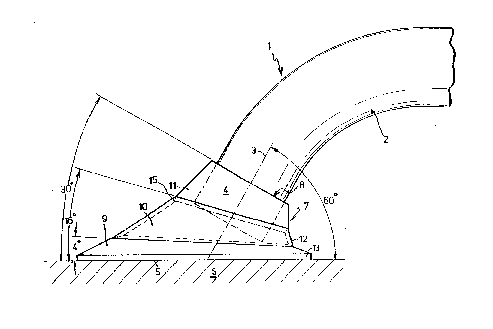
figure 1 is a partial side-view of a preferred embodiment
of the handle according to the invention;
figure 2 is a top-view of a fastening means of the handle
according to figure 1, a cover of which has been removed;
figure 3 is a view of, amongst other, a cross-section of
the fastening means along the line I-I in figure 2;
f figures 4A and 48 show respectively a bottom- and a side-
view of the cover being part of the fastening means
according to figure 2.
In figure 1 a preferred embodiment of a handle 1 according
to the invention is represented. But, for clearness' sake
only part of the handle is shown in the figure, the non-
represented part being constructed in a way corresponding
to the represented part. Hereupon, for that reason the
description of the represented part of the handle 1 will
do.
The handle 1 consists of a substantially oblong handle
portion in this example having the shape of a tube 2 with
a central axis 3 and with a fastening means at the end 4
showing a fastening surface 5. The handle can be fastened
to a wall 6 by means of the fastening means.
The tube 2 is bent over about 60 ° near the end 4 , so that
the central axis 3 and the fastening surface 5 include an
angle of about 60°. This angle of about 60° has turned out

WO 91/06238 ~ ~ PCT/NL90/00168
- 4 -
to be the most favourable in ergonomic respect. In order
to be able to make use of the downwardly sloping ends of
the handle portion as much as possible, the distance of
the axis of the portion of the tube 2 extending parallel
to the mounting surface to the fasting surface 5 is within
a range of 90-100 mms. The diameter of the tube may be
about 30 mms as usual.
On account of the fact that the fastening means comprises
an upstanding portion 7 adjacent to the fastening surface
5 , which encloses the respective end 4 of the tube 2 , the
fastening means is thus suitable for fastening to it the
end 4 of the tube 2, being at an angle of 60° obliquely to
the fastening surface 5. The upstanding portion 7 in this
preferred embodiment is provided with a substantially
circular recess for receiving the end 4 of the tube 2 at
the end faced away from the fastening surface 5. A special
treatment of the end face of the tube 2 can be omitted as
a result hereof, whilst moreover, optionally with addition
of an adhesive, a solid, permanent fastening to the
fastening means is obtained, since the tube is enclosed
and stopped by the fastening means thus constituted.
The upstanding portion 7 is constituted by three super-
posed, obliquely truncated, cone-like bodies 9, 10 and 11.
In figure 1 the cone-like body 10 is represented in dotted
lines, since it is covered by a cover 12.
In figure 2 a top-view of the fastening means is shown,
the cover 12 according to figure 1 having been removed, as
a consequence of which recesses 13 and 14 are visible in
the cone-like body 10 which are intended for receiving
screws or the like, in order to be able to fasten the
handle 1 to the wall 6.

WO 91/06238 ~ ~ S PCT/~L90/00168
- 5 -
As also appears from the drawing, the average diameter of
the cone-like bodies is reduced in the direction from the
fastening surface 5 and parallel to the axis 3 of the tube
2, in order to smoothly connect the tube 2 to the fasten-
s ing surface 5. Therefore, preferably the dimensions of the
lower surface of the cone-like body 9 are equal to those
of the fastening surface 5. This fastening surface 5 may,
of course, also be constituted by the lower surface itself
of the cone-like body 9. As the peripheral portion of each
cone-like body of the fastening means having the smallest
height is present substantially on the side of the
fastening means facing the other, non-represented,
fastening means the most, the angle of about 60 ° can thus
be obtained, the upper faces of the cone-like bodies
respectively being at an angle of about 4°, 16° and 30°,
as also indicated in figure 1. The upper and lower
surfaces of the cone-like bodies have a circular
periphery. The upper surfaces of the bodies 9, 10 and 11
may for instance have a diameter of 69, 44 and 33 mms,
2o respectively.
Preferably, the cone-like bodies 9, 10 and 11 are made in
one piece, as represented in figure 3, in which a cross
section of the fastening means along the line I-I of
figure 2 is shown. A suitable material for the fastening
means is a glass-filled type of nylon. The tube 2 may be
made of steel, optionally with a synthetic coating, or of
synthetic material entirely.
In figure 4A a bottom view of the cover 12 is represented,
and in figure 4B a side-view hereof is represented. By
this cover 12 the recesses 13 and 14 and the respective
screws which have been mounted in the cone-like body 10,
are covered, so that no dirt can pile up herein and the
user cannot get hurt by any burrs of the screws. The cover
12 is also cone-like, in order to obtain together with the

WO 91/06238 ~ g PCT/1L90/OU168
- 6 -
cone-like bodies 9 and ll a perfectly smooth connection at
the periphery of the fastening member. On the inner side,
the cover 12 is preferably directly adjacent to the cone-
like body 10 to transmit forces exerted on the cover 12
during the seizing. In consequence hereof a solid,
painless grip near the fastening means is possible.
Besides, a fine appearance is thus obtained. For the
various parts of the handle various colours can be chosen.
For the fastening of the cover 12 a collar 15 is provided
at the lower surface of the conical body ll, as illus-
trated in figure 1. The collar 15 can constitute a snap
lock with the cover 12 in case the dimensions correctly
correspond to the dimensions of the cover 12. The cover
12, if the same is of a sufficiently flexible material,
may also be provided with a recess extending in axial
direction over the entire height, in order, after having
bent open the cover a little, to apply the same about the
cone-like body 10 or about the tube 2 and consequently to
shift the same over the cone-like body 10. The mutual
dimensions in the latter embodiment are less critical
then.
For correctly orienting the cover 12 when applying same,
projections 16 may be provided, like represented in figure
4, which co-operate with corresponding holes 17 having
been made in the cone-1 ike body 9 , vide figure 2 . Instead
of the projections 16 and holes 17, for the orientation
also a slot may be provided in axial direction at the
periphery of the cone-like body 10, said slot co-operating
with a raised portion present on the inner side of the
cover 12.
The handle according to the invention is particularly
comfortable in use by the design to the fastening means
and by the fact that at least the fastening means is made
of synthetic material.

WO 91 /06238 9 ~ PCT/ L90/00168
It will be clear that the invention is not limited to the
preferred embodiment represented in the drawing and that
many changes in the preferred embodiment described can be
made without leaving the scope of the invention as
described in the enclosed claims.

Dessin représentatif
Une figure unique qui représente un dessin illustrant l'invention.
États administratifs

2024-08-01 : Dans le cadre de la transition vers les Brevets de nouvelle génération (BNG), la base de données sur les brevets canadiens (BDBC) contient désormais un Historique d'événement plus détaillé, qui reproduit le Journal des événements de notre nouvelle solution interne.

Veuillez noter que les événements débutant par « Inactive : » se réfèrent à des événements qui ne sont plus utilisés dans notre nouvelle solution interne.

Pour une meilleure compréhension de l'état de la demande ou brevet qui figure sur cette page, la rubrique Mise en garde , et les descriptions de Brevet , Historique d'événement , Taxes périodiques et Historique des paiements devraient être consultées.

Historique d'événement

Description Date
Le délai pour l'annulation est expiré 2002-11-06
Lettre envoyée 2001-11-06
Inactive : Page couverture publiée 2001-02-08
Inactive : Acc. récept. de corrections art.8 Loi 2001-02-08
Inactive : Correction - Doc. d'antériorité 2001-02-08
Accordé par délivrance 2001-01-16
Inactive : Page couverture publiée 2001-01-15
Inactive : Taxe finale reçue 2000-10-11
Préoctroi 2000-10-11
Lettre envoyée 2000-04-26
Un avis d'acceptation est envoyé 2000-04-26
Inactive : Approuvée aux fins d'acceptation (AFA) 2000-01-11
Inactive : Acc. réc. RE - Pas de dem. doc. d'antériorité 1997-09-18
Inactive : Renseign. sur l'état - Complets dès date d'ent. journ. 1997-09-11
Inactive : Dem. traitée sur TS dès date d'ent. journal 1997-09-11
Toutes les exigences pour l'examen - jugée conforme 1997-07-30
Exigences pour une requête d'examen - jugée conforme 1997-07-30
Demande publiée (accessible au public) 1991-05-16

Historique d'abandonnement

Il n'y a pas d'historique d'abandonnement

Taxes périodiques

Le dernier paiement a été reçu le 2000-09-11

Avis : Si le paiement en totalité n'a pas été reçu au plus tard à la date indiquée, une taxe supplémentaire peut être imposée, soit une des taxes suivantes :

  • taxe de rétablissement ;
  • taxe pour paiement en souffrance ; ou
  • taxe additionnelle pour le renversement d'une péremption réputée.

Les taxes sur les brevets sont ajustées au 1er janvier de chaque année. Les montants ci-dessus sont les montants actuels s'ils sont reçus au plus tard le 31 décembre de l'année en cours.
Veuillez vous référer à la page web des taxes sur les brevets de l'OPIC pour voir tous les montants actuels des taxes.

Historique des taxes

Type de taxes Anniversaire Échéance Date payée
Requête d'examen - générale 1997-07-30
TM (demande, 7e anniv.) - générale 07 1997-11-06 1997-10-29
TM (demande, 8e anniv.) - générale 08 1998-11-06 1998-10-22
TM (demande, 9e anniv.) - générale 09 1999-11-08 1999-10-19
TM (demande, 10e anniv.) - générale 10 2000-11-06 2000-09-11
Taxe finale - générale 2000-10-11
Titulaires au dossier

Les titulaires actuels et antérieures au dossier sont affichés en ordre alphabétique.

Titulaires actuels au dossier
B.V. LINIDO
Titulaires antérieures au dossier
CASPER JACOBUS FRANCISCUS DE JONGE
FRANCISCUS JITTE MARIA NIEUWENHUIS
Les propriétaires antérieurs qui ne figurent pas dans la liste des « Propriétaires au dossier » apparaîtront dans d'autres documents au dossier.
Documents

Pour visionner les fichiers sélectionnés, entrer le code reCAPTCHA :


Pour visualiser une image, cliquer sur un lien dans la colonne description du document (Temporairement non-disponible). Pour télécharger l'image (les images), cliquer l'une ou plusieurs cases à cocher dans la première colonne et ensuite cliquer sur le bouton "Télécharger sélection en format PDF (archive Zip)" ou le bouton "Télécharger sélection (en un fichier PDF fusionné)".

Liste des documents de brevet publiés et non publiés sur la BDBC .

Si vous avez des difficultés à accéder au contenu, veuillez communiquer avec le Centre de services à la clientèle au 1-866-997-1936, ou envoyer un courriel au Centre de service à la clientèle de l'OPIC.

({010=Tous les documents, 020=Au moment du dépôt, 030=Au moment de la mise à la disponibilité du public, 040=À la délivrance, 050=Examen, 060=Correspondance reçue, 070=Divers, 080=Correspondance envoyée, 090=Paiement})


Description du
Document 
Date
(aaaa-mm-jj) 
Nombre de pages   Taille de l'image (Ko) 
Abrégé 1995-08-16 1 78
Description 1997-10-27 7 270
Revendications 1997-10-27 3 92
Revendications 1994-03-11 3 103
Dessins 1994-03-11 3 57
Description 1994-03-11 7 267
Dessin représentatif 2000-12-20 1 10
Dessin représentatif 1999-02-09 1 20
Rappel - requête d'examen 1997-07-05 1 117
Accusé de réception de la requête d'examen 1997-09-17 1 173
Avis du commissaire - Demande jugée acceptable 2000-04-25 1 164
Avis concernant la taxe de maintien 2001-12-03 1 178
PCT 1991-12-11 29 852
Correspondance 2000-10-10 1 32
Correspondance 2001-01-25 2 82
Taxes 1996-10-21 1 67
Taxes 1995-10-18 1 46
Taxes 1993-10-20 1 37
Taxes 1994-10-12 1 46
Taxes 1992-10-22 1 41
Courtoisie - Lettre du bureau 2001-02-07 3 86