Sélection de la langue

Search

Sommaire du brevet 2059089 

Énoncé de désistement de responsabilité concernant l'information provenant de tiers

Une partie des informations de ce site Web a été fournie par des sources externes. Le gouvernement du Canada n'assume aucune responsabilité concernant la précision, l'actualité ou la fiabilité des informations fournies par les sources externes. Les utilisateurs qui désirent employer cette information devraient consulter directement la source des informations. Le contenu fourni par les sources externes n'est pas assujetti aux exigences sur les langues officielles, la protection des renseignements personnels et l'accessibilité.

Disponibilité de l'Abrégé et des Revendications

L'apparition de différences dans le texte et l'image des Revendications et de l'Abrégé dépend du moment auquel le document est publié. Les textes des Revendications et de l'Abrégé sont affichés :

  • lorsque la demande peut être examinée par le public;
  • lorsque le brevet est émis (délivrance).
(12) Demande de brevet: (11) CA 2059089
(54) Titre français: GUIDE POUR PERCEUSE CHIRURGICALE
(54) Titre anglais: SURGICAL DRILL GUIDE
Statut: Réputée abandonnée et au-delà du délai pour le rétablissement - en attente de la réponse à l’avis de communication rejetée
Données bibliographiques
(51) Classification internationale des brevets (CIB):
  • A61B 17/17 (2006.01)
(72) Inventeurs :
  • CROMBIE, JOHN S. (Etats-Unis d'Amérique)
  • KRAG, MARTIN H. (Etats-Unis d'Amérique)
(73) Titulaires :
  • PFIZER HOSPITAL PRODUCTS GROUP, INC.
(71) Demandeurs :
  • PFIZER HOSPITAL PRODUCTS GROUP, INC. (Etats-Unis d'Amérique)
(74) Agent: SMART & BIGGAR LP
(74) Co-agent:
(45) Délivré:
(22) Date de dépôt: 1992-01-09
(41) Mise à la disponibilité du public: 1992-07-16
Licence disponible: S.O.
Cédé au domaine public: S.O.
(25) Langue des documents déposés: Anglais

Traité de coopération en matière de brevets (PCT): Non

(30) Données de priorité de la demande:
Numéro de la demande Pays / territoire Date
07/642,982 (Etats-Unis d'Amérique) 1991-01-15

Abrégés

Abrégé anglais


SURGICAL DRILL GUIDE
ABSTRACT OF THE DISCLOSURE
A drill guide for use in surgical procedures,
especially in implanting spinal fixation devices is
provided, having an extended handle portion in
articulated relationship to a radiolucent drill guide
holder. A drill guide tube is mounted in the drill guide
holder, and has an inwardly chamfered end for gaining a
positive footing in the area to be drilled.

Revendications

Note : Les revendications sont présentées dans la langue officielle dans laquelle elles ont été soumises.


-9-
CLAIMS
1. A drill guide, comprising:
a tubular member having an inner and an
outer wall, a first end portion, and a second end portion
for anchoring said tubular member on a surface in the
area of a location to be drilled, said second end portion
having an internally chamfered surface extending from the
outer wall at said second end of said tubular member,
toward said first end portion of said tubular member, to
the inner wall of said tubular member.
2. The drill guide of claim 1 wherein said
chamfered end portion has a plurality of concave
recesses, and wherein junctures between adjacent concave
recesses form sharp edges ending in points at said second
end.
3. A drill guide for use in surgical
procedures in incisions in a patient, comprising:
a tubular member having first and second
end portions and inner and outer walls, for guiding a
drill bit to a desired location for drilling; and
articulated connecting means for joining
said tubular member to an extended handle, wherein said
connecting means allows for adjusting the orientation of
said tubular member with respect to said extended handle.
4. The drill guide of claim 3, wherein said
articulated connecting means comprises a radiolucent
drill guide holder for spacing other drill guide
components away from said tubular member and avoiding
interference in radiographic images taken while using the

-10-
drill guide, said holder connected to the first end
portion of said tubular member.
5. The drill guide of claim 3, wherein the
second end portion of said tubular member has an
internally chamfered surface extending from the outer
wall of said tubular member at said second end toward the
first end of said tubular member, to the inner wall of
said tubular member, for anchoring said tubular member on
a surface in the area of a location to be drilled.
6. The drill guide of claim S, wherein said
chamfered end portion has a plurality of concave
recesses, and wherein junctures between adjacent concave
recesses form sharp points at said second end.
7. The drill guide of claim 3, wherein said
extended handle is of sufficient length to stabilize said
tubular member by bracing said handle against the
patients body a sufficient distance from the incision to
avoid obstructing the surgical procedure.
8. The drill guide of claim 3, wherein said
connecting means comprises a rod member joined at a first
end to said handle, and a drill guide holder joined at a
first end to a second end of said rod member and at a
second end to said first end of said tubular member, and
wherein said rod member is angularly adjustable with
respect to said handle.
9. The drill guide of claim 8, wherein said
drill guide holder is radiolucent, spacing other non-
radiolucent drill guide components away from said tubular

-11-
member and avoiding interference in radiographic images
taken while using the drill guide, and wherein the second
end portion o. said tubular member has an internally
chamfered surface extending from the outer wall of said
tubular member at said second end toward the first end of
said tubular member, to the inner wall of said tubular
member, for anchoring said tubular member on a surface in
the area of a location to be drilled.
10. A drill guide, comprising:
a tubular member for guiding a drill bit
to a desired location for drilling, said tubular member
having first and second end portions and inner and outer
walls, said second end portion having an internally
chamfered surface extending from the outer wall of said
tubular member at said second end, toward the first end
of said tubular member, to the inner wall of said tubular
member, said chamfered end portion having a plurality of concave recesses, and wherein junctures between adjacent
concave recesses form sharp points at said second end;
an extended handle of sufficient length to
stabilize said tubular member by bracing said handle
against an external surface spaced a distance away from
the location of drilling; and
articulated connecting means for joining
said tubular member to said extended handle, said
connecting means comprising
a rod member having first and second
ends, joined at the first end to said handle,
and
a radiolucent drill guide holder
having first and second ends, joined at the
first end to the second end of said rod member

and joined at the second end to said first end
of said tubular member, said rod member being
positionally adjustable with respect to said
handle and said drill guide holder, for
facilitating adjustment of and controlling the
position of said tubular member with respect to
said handle.
11. A drill guide tube holder for securing a
drill guide tube to a drill guide handle, comprising an
elongated member of a radiolucent material having a first
end portion defining a hole for receiving a drill guide
tube and side portions extending from said first end
portion, said side portions defining a slot there between
and said hole opening into said slot, whereby said side
portions may be spread apart to widen said hole to
facilitate insertion of a drill guide tube and urged
together for biased engagement of the tube.
12. The drill guide tube holder of claim 11,
wherein said radiolucent material is selected from the
group consisting of plastic and fiberglass.
13. A method of guiding a drill for implanting
a fixation device in a spine, comprising:
positioning a tubular member, having a
first and second end portions and a handle structure, for
guiding a drill bit through a pedicle of a vertebra;
aligning said tubular member
concentrically with said pedicle by radiographically
imaging said pedicle and tubular member and adjusting the
position of said tubular member so that the radiographic
image of said tubular member is concentrically disposed

-13-
within a circular image representing said pedicle, and so
that the images of the pedicle and tubular member are
unobscured by the handle structure in the radiographic
image;
anchoring an end portion of said tubular
member on a bony surface overlying said pedicle while
maintaining said tubular member in said alignment,
wherein said tubular member has an inner wall and an
outer wall and a chamfered surface at said second end
portion extending from said outer wall into said inner
wall toward the first end of said tubular member; and
drilling said pedicle by guiding said
drill bit through said tubular member into said pedicle.
14. The method of claim 13, wherein said
tubular member is connected to the handle structure by
articulated connecting means, and said method further
comprising bracing said handle structure against a
surface external to the spine for stabilizing said
tubular member in said alignment.
15. The method of claim 14, wherein said
articulated connecting means comprises a radiolucent
drill guide holder for securing said tubular member to
said articulated connecting means.

Description

Note : Les descriptions sont présentées dans la langue officielle dans laquelle elles ont été soumises.

2 0 ~ 9
SU~(~ICAL DRILL GUIDE
Field of the Invention
The present inven-tion relates to drill guides
used in surgical procedures, particularly involving
spinal fixation.
Backqround of the Invention
Medical treatment of trauma to the spine
includes the implantation of an internal fixation device
to fuse the spine across the injured section. One
example of such a spinal fixation device is known as a
Vermont Spinal Fixator ("VSF"). Design and tes-ting of
VSF devices is discussed at length in M. Krag, et al.,
"An Internal Fixator for Posterior Application to Short
Segments of the Thoracic, Lumbar, or Lumbosacral Spine",
Clinical Orthopaedics and Related Research 203:75-98
(February 1986), which is incorporated herein by
reference.
A VSF generally includes two brace members, one
attached on each side of the spinal column, and each
2~ brace having a pair of screws mounted on either side of
the injured location, and a longitudinal member
connecting the pair of screws to form a rigid structure.
Other similar fixation devices which use screws for
attachment to the pedicle also exist.
According to the standard medical procedure, it
is preferred to mount the screws into the pedicle
portions of the vertebrae This procedure is known from
extensive clinical practice to be reliable, and is
further considered trustworthy based on experiences with
other procedures involving operation on the pedicle, such
as biopsies and bone grafts. The pedicles are pairs of
short, thick protrusions having roughly circular cross-
sections that extend from the anterior body portion to
the posterior and transverse portion of each vertebra.
The cross~sectional area of the pedicle decreases at a
middle region, so that the pedicle is roughly the shape

20~9~89
--2--
of a cylinder with a constriction toward the center of
its length.
Drilling for mounting the VSF screws is done
perpendicularly through the circular cross-section of the
pedicle. A drill guide is used in the procedure to
control the location and orientation of the drill bit.
Precise alignment of the bit is necessary to ensure that
the hole is drilled down the very center of the pedicle.
It is crucial that such alignment be achieved because of
the narrowing portion of the pedicle toward its middle.
If the drilling deviates from its central path, there is
a danger that the bit or subsequently the screw will
break through the side of the pedicle.
The position of the drill bit is controlled by
channeling the bit through a tube, which is part of a
drill guide. In order to determine the exact position of
the tube beyond the tolerances and capabilities of -the
naked eye, radiography is used to ascertain the
relationshlp of the tube to patterns which are detectable
in radiographic images of the bone matter. Specifically,
when the x-ray beam is oriented along the pedicle axis,
approximately perpendicular to the pedicle cross-section,
the pedicle will appear as a ring. The end of the tube
that contacts the bone is then located so as to appear in
the radiograph as within the pedicle ring. The tube is
oriented to be parallel to the x-ray beam so that only
its circular cross-section is visible and not its side
walls. With the drill bit guided by the tube positioned
in this way, correct placement of the drill bit in the
pedicle is provided.
Prior art drill guides employed in the
foregoing procedure have a number of shortcomings.
Although prior guides disclose the basic design of a
l':\'I'KI.\`~22 1'1'

20~9089
guide tube mounted on a handle, it is difficult to
maintain adequate control over the positioning of the
drill bit using such implements. First, the overall
structure of prior art guides is not conducive to
attaining a stable, leveraged positioning of the guide
tube at the drilling location. Second, prior guides are
incapable of adjustment between the handle and the guide
tube, which compromises adaptability to varying
conditions and further contributes to problems with
stability. Third, the prior ark devices fail to address
the desirability of minimizing the interference which the
instruments produce in the radiographic image,
particularly due to interference with the image of the
bony matter caused by metal or other components close to
the tube. Finally, even when proper alignment is
achieved, the guide tubes of prior art devices are prone
to slippage at the end of the tube which contacts the
vertebra.
Summary of the Invention
It is therefore an object of this invention to
provide a drill guide which is of a shape and size that
facilitates stability and control of the instrument
during drilling procedures.
It is a further object of the invention to
provide such an instrument which is capable of adjustment
through a range of positions to further facilitate ease
of use and control of the instrument.
It is another object of the invention to
minimize the interference which the drill guide produces
in radiographic images used during the drilling
procedure.
I :\l`KI ~422 1'1'

20~90~9
--4--
It is yet another object of the invention to
provide a guide tube which is not susceptible to slippage
once positioned at the drilling surface.
These and other objects which would be apparent
to one s}cilled in the art are achieved by the present
invention, which comprises a drill guide having an
extended handle portion in articulated relation with a
radiolucent guide tube holder. A guide tube mounted in
the guide tube holder has an end with an inward chamfer.
The extended handle and articulation of the
instrument permit optimal adjustment and positioning
during the drilling procedure. Specifically, the present
invention can be firmly positioned against a patient's
body to achieve a high level of leverage and stability.
The articulated relationship of the components makes
possible minor adjustments to the position of the guide
tube while the instrument remains firmly in place.
~ignificant advantages are consequently derived in the
ease and effectiveness of use of the instrument.
The guide tube is perpendicularly fixed to the
guide tube holder, which in turn is attached in
articulated relationship to the handle of the drill
guide. The guide tube holder is constructed of a
radiolucent material and shaped to prevent interference
in the radiographic image in the vicinity of the guide
tube.
Fina:Lly, chamfering the end of the guide tube
only on its inner surface as taught by the present
invention prevents slippage of the tube when placed on
sloping surfaces.
I`:\'l'Kl,\i~2 1'1'

20~0~9
--5--
_i f Description of the Drawinqs
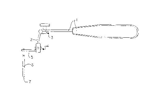
Fig. l is a top view of the drill g~ide
according to the present invention;
Fig. 2 is a side view of the drill guide of
Fig. l;
Fig. 3 is a perspective view of the chamfered
end of the guide tube according to the present invention;
Fig. 4 is a cross-sectional view of the
chamfered end of the guide tube taken along line 4-4 of
FIG. 3;
Fig. 5 is a perspective view of a vertebrae
with the guide tube of the present invention positioned
thereon;
Fig. 6 is a detailed view of a prior art drill
guide tube positioned on a vertebrae; and
Fig. 7 is a detailed view of a drill guide tube
according to the present invention positioned on a
vertebra.
Description_of the Preferred Embodiments
Figs. l and 2 show a preferred configuration of
the present invention. Articulation of the drill guide
is provided by screw clamp 3 which adjustably connects
handle l to rod member 2. This arrangement provides an
articulated connecting means for joining the drill guide
tube 6 to the handle l such that the angle between those
parts may be selectively adjusted. The handle l is of an
extended length to allow the user to brace it against a
surface external to the vertebra being operated on and
space the user's hand away from the x-ray beam. It has
been found particularly useful to brace the handle
against the body of the patient. The ability to brace
the handle 1 in this manner improves the reliability of
1` \1Kl \1?7 1'1'

-6- 2 0~,1?f~9
the drill guide and eases the t`ask of the user during
operating procedures by providing enhanced ability to
keep the guide absolutely steady once the proper position
is attained. Moreover, it is possible to maintain such a
strongly braced position without obstructing the
operating area.
The connection at clamp 3 provides for
adjustment of the angle between handle 1 and drill guide
tube 6. Rod member 2 extends to a second screw clamp 4
provides for attachment and removal of drill guide tube
holder 5. Drill guide tube holder 5 extends from screw
clamp 4, and drill guide tube 6 is mounted in guide tube
holder 5. Guide tube 6 serves to direct the drill bit to
the proper drilling location and maintain its placement
there. It also protects soft tissue around the drilling
area from the rotating drill elements.
As shown in Fig. 1, guide tube holder 5 is
preferably an elongated member having a hole 20 at a
first end for holding guide tube 6, and a slot 22 running
from said hole down the length of the member to the
second end of the member, such that the slot divides the
member between the hole and the second end into two side
portions 21. These side portions are spread apart to
allow for insertion of the guide tube 6 into the hole at
the first end, and are then urged together and clamped in
a closed position at screw clamp 4 to grip guide tube 6
within holder 5. This design of holder S allows for
securing varying sizes of tubes and facilitates
exchanging the tubes for one another. Different diameter
tubes are required depending on the size screw being
implanted. Over sizing of the tube is to be avoided
because of a resulting loss of positional control of the
drill bit within the tube.
I`:\ l KI.\422 .1`1'

-7~ 9~8g
Guide tube holder 5 is preferably of a
radiolucen-t material to avoid causing interference in
radiographic images. The configuration of guide tube
holder 5 also serves to space the metal mass of the
remainder of the drill guide components away from the
critical area of the guide tube, thus further reducinq
radiographic interference. Radiolucent materials
suitable for use with the invention include plastic and
fiberglass.
Figs. 3 and 4 show enlarged views of end 7 of
guide tube 6. End 7 has an internal chamfer 8 so that
the outer wall 9 of guide tube 6 extends slightly further
than inner wall 10. This chamfer 8 allows for tube 6 to
be effectively anchored in the area to be drilled as
shown in YIG. 7. Prior art devices having external
chamfers are inferior for such purposes because they tend
to slip from positions on sloping surfaces. Chamfer 8 is
further characterized by concave recesses 11 around the
circumference of end 7, which form sharp edges ending in
points 12 at the junctures between recesses 11. This
serrated configuration enhances the anchoring of guide
tube 6 in the area of the drilling location.
Fig. 5 shows the drill guide tube 6 of the
present invention positioned at a surface 13 overlying
pedicle portion 14 of a vertebra 15. The advantages of
the internally-chamfered end 7 of guide tube 6 are
demonstrated in Fig. 7. Fig. 6 shows a prior art type of
guide tube having an external chamfer 16. When this
external chamfer 16 is placed on a sloping surface 13
overlying pedicle 14 it can glance off. Thus, prior art
external chamfers lack stability and tend to slip when
pressure is exerted in an attempt to anchor a guide tube.
The use of an internal chamfer 8 in the present

20~9089
invention, as shown in Fig. 7, enables the user to firmly
implant the guide tube even on a steeply sloping surface.
While it is apparent that the invention herein
disclosed is well calculated to fulfill the objectives
stated above, it will be appreciated that numerous
modifications and embodiments may be devised by those
skilled in the art. It is intended that the appended
claims cover all such modifications and embodiments as
fall within the true spirit and scope of the present
invention.
~0
I: \l Kl `~122 I'l'

Dessin représentatif
Une figure unique qui représente un dessin illustrant l'invention.
États administratifs

2024-08-01 : Dans le cadre de la transition vers les Brevets de nouvelle génération (BNG), la base de données sur les brevets canadiens (BDBC) contient désormais un Historique d'événement plus détaillé, qui reproduit le Journal des événements de notre nouvelle solution interne.

Veuillez noter que les événements débutant par « Inactive : » se réfèrent à des événements qui ne sont plus utilisés dans notre nouvelle solution interne.

Pour une meilleure compréhension de l'état de la demande ou brevet qui figure sur cette page, la rubrique Mise en garde , et les descriptions de Brevet , Historique d'événement , Taxes périodiques et Historique des paiements devraient être consultées.

Historique d'événement

Description Date
Inactive : CIB désactivée 2021-10-09
Inactive : CIB en 1re position 2019-11-26
Inactive : CIB expirée 2016-01-01
Inactive : CIB de MCD 2006-03-11
Demande non rétablie avant l'échéance 1996-07-09
Le délai pour l'annulation est expiré 1996-07-09
Inactive : Demande ad hoc documentée 1996-01-09
Réputée abandonnée - omission de répondre à un avis sur les taxes pour le maintien en état 1996-01-09
Demande publiée (accessible au public) 1992-07-16

Historique d'abandonnement

Date d'abandonnement Raison Date de rétablissement
1996-01-09
Titulaires au dossier

Les titulaires actuels et antérieures au dossier sont affichés en ordre alphabétique.

Titulaires actuels au dossier
PFIZER HOSPITAL PRODUCTS GROUP, INC.
Titulaires antérieures au dossier
JOHN S. CROMBIE
MARTIN H. KRAG
Les propriétaires antérieurs qui ne figurent pas dans la liste des « Propriétaires au dossier » apparaîtront dans d'autres documents au dossier.
Documents

Pour visionner les fichiers sélectionnés, entrer le code reCAPTCHA :


Pour visualiser une image, cliquer sur un lien dans la colonne description du document. Pour télécharger l'image (les images), cliquer l'une ou plusieurs cases à cocher dans la première colonne et ensuite cliquer sur le bouton "Télécharger sélection en format PDF (archive Zip)" ou le bouton "Télécharger sélection (en un fichier PDF fusionné)".

Liste des documents de brevet publiés et non publiés sur la BDBC .

Si vous avez des difficultés à accéder au contenu, veuillez communiquer avec le Centre de services à la clientèle au 1-866-997-1936, ou envoyer un courriel au Centre de service à la clientèle de l'OPIC.


Description du
Document 
Date
(aaaa-mm-jj) 
Nombre de pages   Taille de l'image (Ko) 
Revendications 1992-07-16 5 152
Page couverture 1992-07-16 1 12
Abrégé 1992-07-16 1 10
Dessins 1992-07-16 2 32
Description 1992-07-16 8 254
Dessin représentatif 1999-04-28 1 4
Taxes 1994-11-15 1 45
Taxes 1993-11-12 1 30
Correspondance reliée au PCT 1994-03-08 6 170
Correspondance reliée au PCT 1994-04-18 3 82