Note : Les descriptions sont présentées dans la langue officielle dans laquelle elles ont été soumises.
2059146
BCF/RCC/lad
REFRIGERANT HANDLING SYSTEM WITH LIQUID
REFRIGERANT AND MULTIPLE RE~RIGERANT CAPABILITIES
The present invention is directed to refrigerant
handling systems of the type that employ a compressor for pumping
refrigerant through the system, and more particularly to a
device for controlling flow of refrigerant to the compressor
inlet in such a way as to insure that refrigerant at the
compressor inlet is in vapor phase independent of the type of
refrigerant flowing through the system.
Background and Objects of the Invention
U.S. Patent No. 4,768,347, assigned to the assignee
hereof, discloses a refrigerant recovery system that includes
a compressor having an inlet coupled through an evaporator and
through a solenoid valve to the refrigeration equipment from
which refrigerant is to be withdrawn, and an outlet coupled
through a condenser to a refrigerant storage container or tank.
The refrigerant storage container is carried by a scale having
a limit switch coupled to control electronics to prevent or
terminate further refrigerant recovery when the container is
full. The scale comprises a platform pivotally mounted by a
hinge pin to a wheeled cart, which also carries the
evaporator/condenser unit, compressor, control electronics, and
associated valves and hoses.
- 20S9146
There is a need for refrigerant handling equipment,
including refrigerant recovery equipment of the type disclosed
in the above-noted U.S. Patent, that can handle differing types
of refrigerants, such as R12, R22 and R502. U.S. Patent No.
4,939,905, also assigned to the assignee hereof, discloses such
a system, including a multiple-section condenser and means
responsive to refrigerant temperature and pressure at the outlet
of the evaporator for automatically and selectively controlling
flow of refrigerant from the compressor outlet to the individual
condenser sections. However, a problem remains relative to
controlling inlet flow to the evaporator and compressor for
various types of refrigerant so as to maximize overall recovery
speed for either liquid-phase or vapor-phase inlet refrigerant,
while ensuring that refrigerant at the compressor inlet is in
vapor-phase soas to prevent sluggingat thecompressor. Further,
it is desirable to control the inlet refrigerant flow in such a
way as to minimize superheating of the refrigerant in the
evaporator, which reduces efficiency of the handling system and
the amount of refrigerant that can be pumped therethrough.
It is conventional practice to control liquid
refrigerant flow with a flow control device such as a capillary
tube, an orifice tube or an expansion valve. Normally, an
expansion valve can be used to control flow of a single
refrigerant type, necessitating multiple valves for a system
intended to be capable of handling multiple refrigerant types.
A capillary tube can be employed as a compromise to control flow
of multiple refrigerants having liquid feed to the inlet. A
- 2û5914~`
problem with each of these options, however, is that the flow
control device suited for liquid flow control greatly reduces
the flow rate of refrigerant vapor, which would occur the
majority of the time in the case of a refrigerant recovery
system, for example. A sight glass and a manual valve could
be employed so that the operator could observe through the sight
glass whether liquid or vapor refrigerant is flowing through
the system, and manually switch refrigerant flow through a flow
control device where liquid refrigerant is observed, or through
a bypass line when vapor phase is observed. This option requires
manual observation and control. In addition, the flow control
device, such as a capillary tube, would be optimized for one
type of refrigerant, but would be less than optimum for other
refrigerant types where the system is intended to operate with
multiple refrigerant types.
; It is therefore a general object of the present
invention to provide a refrigerant handling system, such as a
refrigerant recovery system, that includes the capability of
handling inlet refrigerant in either vapor phase, liquid phase
or mixed liquid/vapor phase, that is adapted to optimize flow
of refrigerant therethrough as a function of inlet refrigerant
phase, that operates automatically without operator
intervention, that ensures that refrigerant at the compressor
inlet is in vapor phase so as to prevent slugging and possible
damage to the compressor, and that is adapted for use in
connection with multiple differing types of refrigerants.
-
20~9146
Summary of the Invention
A refrigerant handling system in accordance with the
present invention includes a compressor for pumping refrigerant
through the system, and an evaporator connectedtothe compressor
inlet for ensuring that refrigerant fed to the compressor inlet
is in vapor phase. A flow control valve is coupled to the inlet
of the evaporator for controlling flow of refrigerant to the
evaporator. Refrigerant flow through the valve is controlled as
a function of temperature of refrigerant at the evaporator
outlet. Specifically, flow through the evaporator is controlled
such that refrigerant is in vapor phase at the evaporator outlet.
Thus, if liquid refrigerant is being fed to the evaporator
inlet, flow is reduced so that the refrigerant has sufficient
residence time in the evaporator to reach vapor phase. On the
other hand, if inlet refrigerant is already in vapor phase,
flow is increased so at to reduce residence time in the
evaporator, and thus reduce superheating. Mixed liquid and
vapor phase flow rate is between the minimum for all liquid and
the maximum for all vapor.
In a preferred embodiment of the invention, the flow
control valve comprises a thermostatic expansion valve having
first and second pressure inputs, and valve elements for
controlling flow of refrigerant through the valve to the
evaporator as a function of a pressure differential between the
pressure inputs. A first bulb containing refrigerant is
sealingly coupled to the first pressure input of the valve, and
is positioned so as to supply a first control pressure to the
-
2059146
valve as a function of vapor pressure of refrigerant in the bulb
at the temperature of refrigerant entering the evaporator. A
second bulb containing refrigerant is sealingly coupled to the
second pressure input of the valve, and is positioned to supply
a second control pressure to the valve as a function of vapor
pressure of refrigerant in the bulb at the temperature of
refrigerant exiting the evaporator. Thus, flow of refrigerant
to the evaporator is automatically controlled as a function of
refrigerant temperature differential across the evaporator, and
refrigerant flow through the system is automatically maximized
as a function of inlet refrigerant phase or phases.
Preferably, the refrigerant sealed in the first and
second bulbs are of the same refrigerant type -e.g. R502. In
this way, use of temperature differential across the evaporator,
reflected by the vapor pressure differential between the
refrigerant bulbs, automatically accommodates the differing
operating characteristics of other types of refrigerant -e.g.,
R22 and R12.
In a second embodiment of the invention, the flow
control valve comprises a thermal expansion valve coupled to a
temperature sensor responsive to refrigerant temperature at the
evaporator outlet. The valve element is coupled to a heat motor
that is connected in series with the temperature sensor,
preferably a thermistor, across a source of electrical power.
In this way, current to the heat motor, and flow rate through
the valve, are automatically responsive to evaporator outlet
temperature without operator intervention.
--5--
20591~6
Brief Description of the Drawings
The invention, together with additional objects,
features, and advantages thereof, will be best understood from
the following description, the appended claims and the
accompanying drawings in which:
FIG. 1 is a schematic diagram ofarefrigerant recovery
system in accordance with one presently preferred embodiment
of the invention;
FIG. 2 is a fragmentary sectional view of the inlet
flow control valve illustrated schematically in FIG. l; and
FIG. 3 is a schematic diagram of an inlet flow control
valve in accordance with a modified embodiment of the invention.
Detailed Description of Preferred Embodiments
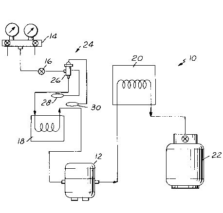
FIG. 1 illustrates a refrigerant recovery system 10
in accordance with a presently preferred implementation of the
invention as comprising a compressor 12 having an inlet that
is coupled to an input manifold 14 through a valve 16 and an
evaporator 18 for adding heat to refrigerant passing
therethrough,and thereby ensuring that refrigerant at the inlet
of compressor 12 is substantially in vapor phase. The outlet
of compressor 12 is connected through a condenser 20 for
extracting heat from and liquefying refrigerant passing
therethrough,toaninlet port of a refrigerant storage container
22. Manifold 14 is adapted for connection to refrigeration
equipment (not shown) from which refrigerant is to be recovered.
When valve 16 is opened, either manually or electronically, and
2059146
compressor 12 is operated, refrigerant is withdrawn from the
equipment under service through evaporator 18 to the inlet of
compressor 12, and is fed from the compressor outlet through
condenser 20 to storage container 22. To the extent thus far
described, system 10 is similar to those disclosed in U.S.
Patent Nos. 4,768,347 and 4,939,905 referenced above.
In accordance with the present invention, an inlet
flow control device 24 controls flow of fluid to the inlet of
evaporator 18. In the embodiment of FIGS. 1 and 2, flow control
device 24 comprises a thermostatic expansion valve 26 having
first and second pressure control input ports 32, 34 sealingly
connected to respective first and second refrigerant bulbs 28,
30. First bulb 28 contains refrigerant of suitable selected
type, and is positioned in heat transfer relationship with
refrigerant entering the inlet of evaporator 18 so that the
temperature of the refrigerant within bulb 28, and the vapor
pressure of such refrigerant fed to valve control port 32, vary
as a function of the temperature of refrigerant at the evaporator
inlet. Likewise, second bulb 30 is coupled to the refrigerant
conduit that the outlet of evaporator 18 so that the temperature
of refrigerant within bulb 30, and the corresponding refrigerant
vapor pressure fed to second valve control port 34, vary as a
function of refrigerant temperature at the evaporator outlet.
Most preferably, the refrigerants captured within bulbs 28, 30
are of the same type, such as R502.
As shown in FIG. 2, valve 26 comprises a valve body
36 having a valve seat 38 and a valve element 40 movable against
2059146
and away from seat 38. A valve inlet fitting 42 is coupled to
valve 16 (FIG. 1) for feeding refrigerant to one side of valve
element 40. A valve outlet fitting 44 feeds refrigerant to
compressor 12 from the opposing side of the valve seat. A coil
spring 46 is captured in compression within valve body 36, and
urges element 40 toward a closed position against seat 38.
Element 40 is coupled by a shaft 48 to pair of axially opposed
diaphragms 50, 52 captured in respective axially opposed
diaphragm chambers. The outer sides of the diaphragms chambers
are coupled to valve pressure control input ports 32, 34
respectively. A small passage 54 bypasses valve element 40 and
seat 38 so as to meter refrigerant from inlet fitting 42 to
outlet fitting 44 independent of valve position.
Thus, vapor pressure of refrigerant in bulb 28 combines
with spring 46 to urge valve element 40 against seat 38, and
to block flow of refrigerant through valve 26. On the other
hand, vapor pressure of refrigerant within bulb 30, positioned
at the outlet of evaporator 18, urges valve element 40 away
from seat 38 against the force of spring 36 and the control
pressure from bulb 28. Use of the same type of refrigerant in
both bulbs 28, 30 allows flow control 24 to operate in conjunction
with other types of refrigerant flowing through system 10,
different from the type of refrigerant in the bulbs. As an
example of operation, if liquid R22 is fed to valve inlet fitting
42 at 85F, and the evaporator discharge temperature is 40F,
bulb 28 might provide a first control pressure to valve 26 equal
to 70 psig (R502 saturation pressure at 33F), the outlet
--8--
20~9146
pressure of valve 26 might be 59 psig (R22 saturation pressure
at 33F), and the control pressure at bulb 30 might be 80 psig
(R502 saturation pressure at 40F). Spring 40 would be set
under these conditions to provide refrigerant flow at a pressure
differential of 10 psig, which would control superheat in
evaporator 18 to 7F (including pressure effects).
FIG. 3 illustrates a modified flow, control device
24a that includes an electric expansion valve 50 having a heat
motor 52 coupled to a valve element 40a. The heating element 54
of motor 52 is connected in series with a thermistor 56 across
a source of electrical power. Thermistor 56 is positioned
adjacent to the outlet of evaporator 18 so as to be responsive
to the temperature of refrigerant exiting the evaporator outlet.
Thus, an increase in temperature at the evaporator outlet reduces
current to that motor 52. Such reduced current to heat motor
52 moves valve element 40a away from valve seat 38a, allowing
passage of morerefrigerant to evaporator 18, and thereby tending
to reduce temperature at thermistor 56. Conversely, reduced
temperature at thermistor 56 closes valve element 40a toward
seat 38a reducing refrigerant flow.
Although the invention has been disclosed in
connection with a refrigerant recovery system 10 illustrated
in FIG. 1, which is a presently preferred implementation of the
invention, the invention in its broadest aspects is by no means
limited to refrigerant recovery implementations. Indeed, the
invention finds application in any type of refrigerant handling
system in which a compressor is employed for pumping refrigerant
2059146
through the system, in which the inlet refrigerant may be in
liquid or mixed liquid/vapor phase, and/or in which inlet
refrigerant may be of multiple differing types.
--10--