Note : Les descriptions sont présentées dans la langue officielle dans laquelle elles ont été soumises.
W091/01852 2 ~ ~ 9 ~ 6 ~: PCT/GB90/01222
IMPROVEME~TS R~L_TI~5 TO CUTTI~lG APPA~AT~S
.
This invention relates to cutting or abrading apparatus,
and relates specifically to a jet cuttlng or abrading
apparatus wherein a cutting fluid comprising a liquid
carrier and abrasive is jetted in a fine stream to act
as a cutting lance Eor cutting, -or exam?le, rigid shee~
materials.
A par,icula~ a?plication for the ?rese - inven~ o
com?rises the cutting of lin ngs of ~i?es ~su_bi as
underground sewers) where such linings bioc~ connec .ons
between lateral connecting pipes and the main sewer.
The invention may also be used ~or cutting obstructions
in pipes.
It is known for example from British Patent No. 1449455
to line a sewer to repair or rehabilitate same using
soEt flexible lining material whicll is in ~he nature o~
a fibrous ~el~ im2regna~e~ ~i.l a ~Jra~`e s~nthe-i-
resin. The lining tube is a?plied to the se~er s~Jrfaee
and is then held in position until the resin cures to a
hard condition froming a rigid l.ning pipe. In this
process, the lining tube must be applied over the
lateral connecting pipe.s, and these laterals must re re-
opened using a cutting means which is placed in the
lined pipe. The cutting apparatus oE the present
invention is particularly sulta~le for this c~tting
operation in that the Eine high ?ressu~e citting je~ can
be used to cut a "coupon" Ero~ t~e lining in register
with the lateral connection to be re-es~ablished b~
appropriate manipulation of the cu ting jet.
According to the present in~entlon there is ?ro~ide~ a
method of high ?ressure jet cu ng com?rising feeding
.
, ,, . -, : ~ . . : . .
- . . . - - - - , . . .... .
WO91/0185~ PCT/GB90/0122~
&
high pressure liquid carrler and an abrasive composition
comprisin~ abrasive particles in suspension to a mixins
head, deliverin~ the resultin~ mixture to a nozzle from
which said issues as a high pre~asure cutting jet or
je~s.
.
The carrier fluid preferably is water at a pressure in
the order o~ U? to 4,000 psi.
It is known that water jet cutl:ing can be enhanced i'
abrasive particles such as sand particles can be
er.rained i~ the water, and this has already been
pro2osed accordin~ to one ar-an~emen _a ~isclose~ in
European patent no. 0 152 223.
In the said European patent, it is proposed to carry the
abrasive particles to the nozzle along a separate supply
line, and using air as a carrier medium to transport the
abrasive particles. Immediately prior to mixin~ of the
abrasive particles with the water at a mixing head, the
carrying air and sand are separated, the air being
vented, and the sand being carried through to the mixing
head to mix with the water to become entrained therein
and the mixture is expelled ,'-rom a nozzle.
This system works satisfactorily, but if there is
failure of the air supply, the sand simply settles in
the supply tube and is not satis~actorily taken up by
; the nozzle head.
The present invention provides for the delivery of
abrasive particles to the mixin~ head, in a 'luent
medium of such as to form wi~h the abrasive particles a
suspension in which the abrasive particles are suspended
in such a fashion that if there is failure in the supply
?ressure delivering the mixture to the nozzle head, the
particles ~ill not ~all Olt o' s~spension. This
arran~emen~ also has the considerable advanta~e tha~ the
:,
.' ~ .
-- . - . . . - . . . . .
- : : , . . . . .
. , . . . .. . .. -
WO91/01852 PCTtGB90/01222
: 3 ~9~
supply o~ the abrasive composition can be stopped and
restarted without any deleterious effects.
It will ~e understood t~lere'ore t~at i' t~ere is a
~ailure of the pressure supplying the mixture tO the
nozzle head, even if this is a negative inducing
pressure, the mixture will simplv remain in the supply
line with the particles in suspension unt-1 .such times
as the ?ressure is re-esta~lishe~, when tne ~ixture ~ill
be carried forward to the nozzle head as ' tnere had
been no breakdown in the supply ~ressure.
Typica ly, the abrasive mater.a' ma~ ~e sanA, an~ a
suitable fluent material ~or slspending sand .s
water with a thickening thixotropic agent.
The mixture may be drawn into the high pressure water at
the mixing head by virtue of venturi action.
.,
Preferably, the abrasive composition is delivered at a
slower speed than the water to the mixing head, but at
said mixing head the abrasive composition is acceletated
Ilp to the speed of the water so that there is ef~ec~ive
mixing. for delivery to the noz~'e.
, . ,
Preferably, the ratio o~ the throat restrictor ~or the
abrasive compositions to that for the water, at the
mixing head, as in the order o 3:20.
..
: The abrasive composition is preferably delivered to the mixing head by a twin piston pump arrangement the
~ pistons being connected in a bac~ to bac`~ or push-pull- configuration.
The water may be delivered by means of a high pressure
water pump.
,
~ The instant invention is also concerlle~ with the
-
:
. : . . ,. .. . - .. , . ,, , ~; :,,: , ,
WO91/0]852 ~ PCT/G~90/01222
~t~
apparatus for providing the fluid cuttin~ ~et, and also
in accordance with the presen. invention, a high-
pressure fluid cutting je~: ~2?ara~U5 com2 -ed an outlet
nozzle for the jet, means supplving d car.i'r l:quid
under pressure to the nozzle ani means for su?~lying a
fluent composition comprising or containin~ ~he abrasive
particles in suspension to said jet so tha~ the li~uid
and composition mix in a mixing head to for~.. the final
cutting jet, said means for supplyin~ the fluen~
composition comprising a pump means dr:ven bv the
pressure of the carrier liquid.
The said punp means preferab:~y cOm?- 5~-c - ?a1r o
piston pumps arranged back to bac'~ s~ o ha~e a
common piston rod, with appr~?riate val~;;ng ?rov1ding
that the pressurised carrier liauid is ap?lied
alternately to the crown side of the p!ston of each
pump, whilst the fluent composition is pumped by the rod
side of the respective piston pumps and alternately,
thereby to provide augmentation of the pressure in the
fluent composition.
The fluent composition is p-eferably su??lled t_ the
mixing head through a passage which is a frt^~ion o' the
area of the passage through which the carrier liquid is
supplied in order that the carrier liquid can ~e ap?lied
in substantially greater voiume to the ~e~ than the
~luent composition, but so that the composition and
carrier liquid are supplied to the jet at substantially
the same velocity in order to ensure homogenous mixing
of carrier liquid and fluent compo.sition.
The apparatus may embody a control shut~le valve
controlling the supply of the carrier iiauid under
pressure to the alternate piston ?umps, so tha- as one
pump is pressurised, the othe^ :s exhaus~a-`, t~e shut~le
valve being switched by a meanâ couple,1 to the sa~d
common piston rod, and the ou~ e s from tn_ crown sides
.! - ~ . . ~ : ' :
" ~' '. ' ' . ' ' , ' , ' ' ' '' ~ ' . ' ' . , :, . . . , ' '
'' ' ~' ' ' , ' : ,' ', ' ~ '' ' . :,
'. , ~ :, '' ' ' ,
. ' , ' ' , ,, ' ' , . ' ' . ' .
',
. ' . . ' . . .
.
W091/01852 PCT/GB90/OlZ22
2 ~ ~ ~ 6 6
of the piston pumps being provided with appropriate one-
way valves to ensure that as fluent composition is being
pumped from one o' said rod s:des to the nozzle, t~e
other is drawing in a fresh su?plv o.' tne~ fluent
composition ready to be charged to the nozzle at the
next stroke of that pump.
The mixing head and nozzle may ~e as se. ~orth in
British Patent Application ~o. 9009072.1. Embodiments
of the present invention will now be described by way of
example, with reference to the accompanying diagrammatic
drawings, wherei~
Fig. 1 is a ciruit diagram of t~e hydra~ circ~ ~ of
apparatus according to a ~irst embodiment o. the
present invention;
., .
Fig. 2 is a view of an apparatus according to a second
embodiment of the invention.
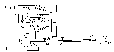
Referring to Fig. 1, the hydraulic circuit of the
apparatus according to the embodiment of the invention
comprises a water tank 10, water forming the pressurised
liquid component of the system, a tank 12 for the
composition of carrier matrix and abrasive, and a
mixing head 14 to which a pressurised water line 16 and
a pressurised fluent composition line 18 lead so that in
the head 14, pressurised water and fluent material under
pressure are mixed and together then pass along pipe 15
to an outlet nozzle 14A from which 14A and head 14 may
be combined into a single un-t to perform the cutting
operation.
The water travels in line 16 at greater speed than the
composition in line 18 but in the head 1& are
restrictors x and y for the composition flo~ and water
~low in order to ensure that the composition and ~ater
meet at substantially the sa-,e velocit~. Su tably, the
;. -- - . , : . . -: ~ :
. .
WO91/01852 PCT/GB90/01222
'~ ~J`~
composition restrictor x may be 3~20tns ~' the cross-
sectional area of the water restrictor y.
.~ .
The water is drawn from tank 10 ~y means of a pump 22
wllich may sup?ly water a~ 21 litres pe- ~inute a~ a
pressure in the order of 2,000 psi The ou~put line 24
irom the pump 22 leads directly to the noz~lG 14, b~t
also has a branch line 26 containing a 'low control
valve 28 to divert say in th* order o' 3 litres per
minute throu~h a shuttle val-- 3~1 d~p~ ^ upon ~-
position as will be explained hereinaftei-
The fluent composition is drawn from the tank 12 t~either one of a pair o ?umps 32, 34 ~ ich co~pr~sG
piston and cylinder devices, and the p.s~ons 36, 38 are
arranged on a common piston rod 40 so thac pumps 32 and
34 are arranged back to back ~ centralising spring
arrangement serves to bias the piston rod to the
centralised positi~n shown in i-ig 1 The composition
is drawn from the tank 12 through a line 44 and either
oE two non-return valves 46, 48 in lines 50, 52 leading
to the rod sides of pumps 32 and 34.
...
Two outlet pipes .rom pumps 32 an_ 3 indicate~
re~erence numerals 54 and 56 contain non-retuirn valves
58 and 60 and lead to an outlet line 62 which in turn
couples with the fluent composition outlet pipe 18.
Operation of the apparatus oE ri9. 1 will be understcod
from the above. When the apparatus is operational, the
pistons 36 and 38 will be displaced back and forth in
the pumps 32 and 34 and will operate the shuttle valve
30. ~ssume that the shuttle valv~ 30 is to the right-
hand side of the blocking posi~ior, showr in Fi~ 2 ~n
this case high pressure wateir ~rom tne pump 22 is
charged into the crown end o' pump 34 d splacing the
piston 3~ to the right oE ~ig 2 and ~orcing the
composition in the rod side o' .h~ pisto tnr~ug~i line
'
.... .. . . . . , : . .: ...................... . .:
:' ' . ; . ' ' ' . : - . . :.
, ' . . ~' ~' ' ,
WO91/01852 PCT/GB90/01222
7 2
52, valve 60, line 56 and lin~ 62 ~o the n;~z%le l~ A~
the same time high pressure water is pumped via the line
24 to the nozzle 14
As regards the pu,mJ 32 during this opera.io,-" wa~er on
the crown side of the piston 36 is forced through line
64 and the shuttle valve 30 to a return line 66 so that
the water is returned to the t~nk, and at the same time
a fresh supply o~ the fluent composition is drawn from
tank 12 through line 44, valve ~6 and line 50 into the
rod side of the pump The pisLon pair moves to the left
until a detent on the rod 40 engages an operating leg of
; tne shuttle valve displacing the shuttle valve t_ i~s
extreme ri~ht hand position in h~`nl^~ ?iston 3, and the
movement o~ the piston assem~lAv eeverses so tha. the
fluent composition im pump 32 is now discharged
through line 50 o valve 58 and into line 62
A continuous supply of the Lluen~ composition and water
; through nozzle is therefore ensured, but the system can
be stopped by stopping the pump 22 The amount of water
which is used for displacing the pistons can be
controlled by adjustment of th- ~lo~ contr~l valve 28
.~ .
In an embodiment of the invention in Fig 2, the
, apparatus, comprises a nozzle head lOX containing a
,' nozzle outlet 12X from which the high velocity je. of
water issues, the water being sùpplied via a high
pressure water hose 14 at a pressure in the order o~
; 3,000 P.S.I. at 4 gallons per minute.
In the nozzle head lOX, the pipe 14X leads to a venLuri
chamber 16X which is traversed ~y a feed pipe l8X ~or
the mixture of the abrasive composi~ion The
composition is drawn in accordance with well-established
;, venturi principles into the venturi chamber 16X in use
through a small aperture 20X in t~,- pipe l4X and ~acing ~ ,
the nozzle 12X The abrasive com?osition ;s pumpe^,
WO 91/01852 PCI/GB90/01222
. .
: .
means o~ a motor 22X whic~ ~rivcs -a fe~ a~g.~t~ , in
chamber 26x, to which the material is ~ ro~ a ~.ora~
hopper 28x.
The source of the material in .~pper 2Q~: and ~ .s~rce
of high pressure water may be .ocated re~t~ly ro.~ tne
nozzle head lOX which typically ~ill be loctated in
.~ the pipeline where cutting is to take place.
.,
cross-connecting pipe 30X _~up!e.- ~,e ~ee~ ?ila- l3`;
for the composition and the water plpe l~X ani
contains a flushing valve 32X wnich is normallv closed,
.; but which can be opened when it i.s required to pu~,2
water through the pipe 18X in order ~o flush same ~f
residual composition and/or abrasive.
.~ .
, .
The composition is such that the carrier mediu~ and the
: abrasive are of like density and/or specific gravity so
that the abrasive particles will remain in suspension in
the carrier even in the event of Eailure of the pump
22X. In other words as in the Fig. I embodlmen~ there
. will be minimum or no set~ling out o~ the abrasive even
. when the system is not operational, dis~inguis~ing the
. method and apparatus from the known arrangements.
- :
. Various materials may be used as the ahrasive
;- compositon, depending upon the natural interval being
cut, provided that the abrasive particles do not settle
~ out of suspension too quickly (if at all) when the
composition is left standing. 1- the par~icles se~
out within one hour the composi~ion being leEt standing,
: that would be considered too quick.
., - : : .- . . .: .:
, .
.
WO91/~1852 9 PCT/GB90/01222
6 ~ ~
A suitable composition may comprise, by weight, the
: following:-
,
:. a) ~ater200 parts
b) Sand200 ?arts
c) Thickening agent ~ parts
d) Lubricating agent
(to lubricate pump) ' ~arts
. This composition may be mixed by weight Wit'l the water
: in the retes o' ~ tO o (one ?ar. com?osi~ on to si~ -
parts water).
.^
, .
: . ~
' ,