Sélection de la langue

Search

Sommaire du brevet 2060305 

Énoncé de désistement de responsabilité concernant l'information provenant de tiers

Une partie des informations de ce site Web a été fournie par des sources externes. Le gouvernement du Canada n'assume aucune responsabilité concernant la précision, l'actualité ou la fiabilité des informations fournies par les sources externes. Les utilisateurs qui désirent employer cette information devraient consulter directement la source des informations. Le contenu fourni par les sources externes n'est pas assujetti aux exigences sur les langues officielles, la protection des renseignements personnels et l'accessibilité.

Disponibilité de l'Abrégé et des Revendications

L'apparition de différences dans le texte et l'image des Revendications et de l'Abrégé dépend du moment auquel le document est publié. Les textes des Revendications et de l'Abrégé sont affichés :

  • lorsque la demande peut être examinée par le public;
  • lorsque le brevet est émis (délivrance).
(12) Demande de brevet: (11) CA 2060305
(54) Titre français: CONNECTEUR DE CORDONS ELECTRIQUES
(54) Titre anglais: ELECTRIC CORD CONNECTOR - THE SNAP
Statut: Réputée abandonnée et au-delà du délai pour le rétablissement - en attente de la réponse à l’avis de communication rejetée
Données bibliographiques
Abrégés

Abrégé anglais


ABSTRACT OF THE DISCLOSURE
An electric cord connector is provided and consists of a
base member and a cap member that can be readily snap locked
together so that electric cords extending therefrom will be in
an operative electrically connected condition when pointed tip
pins carried in the cap member pierce the electric cords.
-10-

Revendications

Note : Les revendications sont présentées dans la langue officielle dans laquelle elles ont été soumises.


CLAIMS
What is claimed is:
1. Electric cord connector comprising:
a) an insulated base member having a chamber with at
least one aperture formed offset in each end wall thereof for
receiving electric cords to be coupled;
b) an insulated C-shaped cap member having a pair of
flexible side legs adapted to be received by said base member;
c) means for assembling said base member and said cap
member together in a locked position; and
d) means for electrically connecting the electric cords
when said base member and said cap member are assembled
together.
2. Electric cord connector as recited in Claim 1
wherein said locking means includes:
a) said base member having a groove formed in each
outer side wall thereof; and
b) said cap member having a lip formed on each inner
distal end of each said side leg so that said side legs can
flex to allow said lips to snap under said grooves in said
side walls of said base member for a locked connection when
assembled together.
-8-

3. Electric cord connector as recited in Claim 2,
wherein said coupling means includes:
a) said base member having a pair of spaced apart
parallel holes extending into said chamber transversely into
axis of said apertures; and
b) a pair of pointed tip pins carried in a spaced apart
parallel relationship in said cap member, extending inwardly
between said side legs and adapted to be received into said
holes to pierce the electric cords so as to electrically
connect the electric cords together when said base member and
said cap member are assembled together.
4. Electric cord connector as recited in Claim 3,
further including said base member having a second groove
formed in each outer side wall in a spaced apart parallel
relationship with each said first groove so that said lips on
said legs can fit into said second grooves in a partially open
condition prior to the electric cords insertion into said base
member.
-9-

Description

Note : Les descriptions sont présentées dans la langue officielle dans laquelle elles ont été soumises.

~0~3~
E~ECTR~_Ç~D~2~NECTQR~ "TE~ a~
BAÇKGROUND QF T~E INyENTION
The instant invention relates generally to wire
connectors and more specifically it relates to an electric
cord connector.
Numerous wire connectors have been provided in the prior
art that are adapted to bridge together insulated wires so as
to replace the customary twisted wire splices. For example,
U.S. patents numbered 2,587,239 to Smith; 4,547,033 to White
et al and 4,612~423 to Munroe all are illustrative of such
prior art. While these units may be suitable or the
particular purpose to which they address, they would not be as
suitable for the purpose of the present invention as hereafter
described.
--1--

~6~
$UMMARY QF~T~E~I~z~ Q~
A primary object of the present invention is to provide
an electric cord connector that will overcome the shor-tcoming
of the prior art devices.
Another object is to provide an electric cord connector
in which a base member and a cap member can be readily snap
locked together so that electric cords will be in an operative
coupled condition.
~ n additional object is to provide an electric cord
connector in which the assembly between the cap member and
base member can be accomplished without the use of special
tools or skills.
A further object is to provide an electric cord
connector that is simple and easy to use.
A still further object is to provide an electric cord
connector that is economical in cost to manu~acture~
Further objects of the invention will appear as the
description proceeds.
To the accomplishment of the above and related objects,
this invention may be embodied in the form illustrated in the
accompanying drawings, attention being called to the fact,
however, that the drawings are illustrative only and that
changes may be made in the specific construction illustrated
and described within the qcope of the appended claims.

BRIEF DESÇRIPTION OF T E DRAWIN~ U~ES
The figures in the drawings are briefly described as
f ollows:
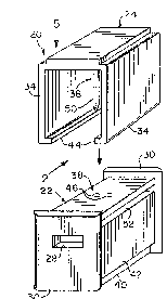
Figure 1 is a greatly enlarged perspective view o~ the
instant invention showing the cap member disengaged from the
base member;
Figure 2 is an end elevational view taken in the
direction of arrow 2 in Figure 1 showing the connector in a
partially open condition prior to the electric cord insertion
and engagement thereof;
Figure 3 is a side elevational view taken in the
direction of arrow 3 in Figure 2;
Figure 4 is an opposite end elevational view taken in
the direction of arrow 4 in Figure 3;
Figure 5 is a top plan view taken in the directi.on of
arrow 5 in Figure 1 showing two electric cords coupled
together therein;
Figure 6 a cross sectional view taken along line 6-6 in
Figure 5;

3 ~ ~3 ~
Figure 7 is a fragmentary elevational view of the
invention shown in section, illustrating a lip of the cap
member in locking engagement with a side groove of the base
member;
Figure 8 is similar to Figure 6 but illustrates a second
embodiment of the invention that couples three electric cords
together;
Figure 9 is an end view taken in the direction of arrow
9 in Figure 8 and also shows the electric cords removed
lQ therefrom~
Figure 10 is an opposite end view taken in the direction
of arrow 10 in Figure 8 and also shows the electric cords
removed therefrom; and
Figure 11 is a diagrammatic end elevational view showing
a third embodiment of the invention that may be employed to
couple typically at least six electric cords together.

3 ~t~ ~
D~ILED DE~~IPTIQN OF THE_~ ERRED EMBQDIMENT5
Turning now descriptively to the drawings r in which like
reference characters denote like elements throughout the
several views, the Figures illustrate an electric cord
connector 20 consisting generally of an insulated base member
22 and an insulated C-shaped cap member 24. The base member
22 has a chamber 26 with at least one aperture 28 formed
offset in each end wall 30 thereof for receiving electric
cords 32 to be coupled. The cap member 24 has a pair of
lQ structure 36, as best shown in Figure 7, that are provided for
assembling the base member 22 and the cap member 24 in a
locked position while another structure 38, as best shown in
Figures 6 and 8, is provided Eor coupling together the
electric cords 32 when the base member 22 and the cap member
24 are assembled together.
The locking structure 36 includes the base member 22
having a groove 40 formed in each outer side wall 42 thereof.
The cap member 24 has a lip 44 formed on each inner distal end
of each side leg 34 so that the side legs 34 can flex to allow
the lips 44 to snap under the grooves 40 in the side walls 42
of the base member 22 of a locked connection when assembled
together.
The coupling structure 38 includes -the base member 22
having a pair o~ spaced apart parallel holes 46 extending into
the chamber 26 transversely into axis 48 of the apertures 28.
A pair of pointed tip pins 50 are carried in a spaced apart

3 ~ j
parallel relationship in the cap member 24, e~tends inwardly
between the side legs 34 and adapted to be received into the
holes 46 to pierce the electric cords 32 so as to electrically
connect as well as mechanically couple the electric cords
together when the base member 22 and the cap members 24 are
assembled together.
The base member 22 has a second groove 52, as best seen
in Figure 1, formed in each outer side wall 42 in a spaced
apart parallel relationship with the ~irst groove 40. The
lips 44 on the legs 34 can fit into the second grooves 52 in a
partially open condition prior to the electric cords 32
insertion into the apertures 28 in the base member as shown in
Figures 2, 3 and 4. This keeps the connector 20 in a ready to
be used condition.
The connector 20 can be structured to utilized two
electric cords 32, as best seen in Figure 6, three electric
cords 32, as best seen in Figure 8, and six electric cords 32,
as best seen in Figure 11. Other combinations not illustrated
can also be utilized by simply changing the relative size of
~0 the base member 22 and cap member 24 to accommodate various
amounts of electric cords 32.
To use the connector 20 a person simply places the
electric cords 22 into their respective apertures 28 in the
base member 22~ The cap member 24 and the base member 22 are
then pressed together until the lips 44 enter the grooves 40
so that the pins 50 can pierce the electric cords 32. The cap

2~3~ ~
members 24 and base member 22 are now locked toge-ther to keep
the electric cords 32 coupled to each other.
While certain novel Eeatures o~ this invention have been
shown and described and are pointed out in the annexed claims,
it will be understood that various omissions, substitutions
and changes in the forms and details of the device illustrated
and in its operation can be made by those skilled in the art
without departing from the spirit of the invention.
--7--

Dessin représentatif
Une figure unique qui représente un dessin illustrant l'invention.
États administratifs

2024-08-01 : Dans le cadre de la transition vers les Brevets de nouvelle génération (BNG), la base de données sur les brevets canadiens (BDBC) contient désormais un Historique d'événement plus détaillé, qui reproduit le Journal des événements de notre nouvelle solution interne.

Veuillez noter que les événements débutant par « Inactive : » se réfèrent à des événements qui ne sont plus utilisés dans notre nouvelle solution interne.

Pour une meilleure compréhension de l'état de la demande ou brevet qui figure sur cette page, la rubrique Mise en garde , et les descriptions de Brevet , Historique d'événement , Taxes périodiques et Historique des paiements devraient être consultées.

Historique d'événement

Description Date
Inactive : CIB expirée 2018-01-01
Inactive : CIB de MCD 2006-03-11
Le délai pour l'annulation est expiré 1995-07-29
Demande non rétablie avant l'échéance 1995-07-29
Réputée abandonnée - omission de répondre à un avis sur les taxes pour le maintien en état 1995-01-30
Inactive : Demande ad hoc documentée 1995-01-30
Demande publiée (accessible au public) 1993-07-30

Historique d'abandonnement

Date d'abandonnement Raison Date de rétablissement
1995-01-30
Titulaires au dossier

Les titulaires actuels et antérieures au dossier sont affichés en ordre alphabétique.

Titulaires actuels au dossier
MARCELLA PEARL
MARCELLA PEARL
Titulaires antérieures au dossier
S.O.
Les propriétaires antérieurs qui ne figurent pas dans la liste des « Propriétaires au dossier » apparaîtront dans d'autres documents au dossier.
Documents

Pour visionner les fichiers sélectionnés, entrer le code reCAPTCHA :


Pour visualiser une image, cliquer sur un lien dans la colonne description du document (Temporairement non-disponible). Pour télécharger l'image (les images), cliquer l'une ou plusieurs cases à cocher dans la première colonne et ensuite cliquer sur le bouton "Télécharger sélection en format PDF (archive Zip)" ou le bouton "Télécharger sélection (en un fichier PDF fusionné)".

Liste des documents de brevet publiés et non publiés sur la BDBC .

Si vous avez des difficultés à accéder au contenu, veuillez communiquer avec le Centre de services à la clientèle au 1-866-997-1936, ou envoyer un courriel au Centre de service à la clientèle de l'OPIC.

({010=Tous les documents, 020=Au moment du dépôt, 030=Au moment de la mise à la disponibilité du public, 040=À la délivrance, 050=Examen, 060=Correspondance reçue, 070=Divers, 080=Correspondance envoyée, 090=Paiement})


Description du
Document 
Date
(aaaa-mm-jj) 
Nombre de pages   Taille de l'image (Ko) 
Dessins 1993-07-29 1 44
Revendications 1993-07-29 2 47
Abrégé 1993-07-29 1 10
Description 1993-07-29 7 167
Dessin représentatif 1998-10-12 1 8
Taxes 1994-01-23 1 37