Note : Les descriptions sont présentées dans la langue officielle dans laquelle elles ont été soumises.
Z~ 3
LENS AND METHOD OF MARING SAME
FIELD OF THE INVENTION
This invention relates to a lens and the method of
making it and in particular to a lens for use on lamp
assemblies of an automotive vehicle, for example a rear
lamp assembly, and comprises a combination of optic
elements and reflex elements.
BACKGROUND OF THE INVENTION
Conventionally, the outer lens portion of automobile
lamp assemblies whether used on the rear, front or side
surfaces thereof, have been divided into two or more
distinct sections. At least one of these sections
includes optical elements which transmit light from a
light source in the assembly outwardly thereof, as is the
case in the "taillight" sections or "brake light"
sections, and another section made up of reflex elements
the purpose of which is to reflect light from an exterior
light source directed at the lamp assembly. As an
example, optical elements of the lens are located
outwardly of a light source in the body of the assembly.
The optical elements, or optics as they are sometimes
referred to, direct and transmit a first light source,
for example a taillight bulb, and they also serve to
direct and transmit the stronger light resulting from a
brake application, or a directional signal in the case of
a front or side located assembly, resulting from a higher
intensity bulb being brought into play with a brake
application or directional signal actuation. The reflex
- 2 - 2060703
portion of the assembly consists of an arrangement of a
plurality of multi-faceted elements that provide a
reflective brilliance to a light source directed at the
assembly from the exterior thereof, for example, from the
head lights of another automobile being directed at a rear
lamp assembly incorporating the reflex elements in
question. The brilliance of the reflective elements must
meet standards set by various countries.
Examples of the prior art may be found in German
Offenlegungsschrift 2 230 584, 28 December 1972,
U.S. Patent 3,632,695 of January 4, 1972; and
U. S . Patent 4,198,182 of April 15, 1980.
DE-A-2 230 584 illustrates a plane of optical elements
parallel with a plane of reflex elements.
U. S . patent 3,632,695 discloses a method of making a
combined lens and reflector in which a plurality of pins
having shaped ends are assembled in a bundle and replacing
portions of the shaped ends where optical elements are to
be formed. A mold is electroformed over the shaped ends
and subsequently the electroform mold is shaped at the
areas of the optical elements to form the desired optical
surfaces.
U.S. patent 4,198,182, there is disclosed a lamp lens
mold in which the mold plate has a plurality of recesses in
one face thereof and in which each of the recesses is
adapted to produce a projection on one face of the lens
element and is shaped so as to define in the pro~ection a
lens integral with and overlying a prism.
Automotive lamp assemblies and their lenses are
relatively simple to manufacture when the areas of the
vehicles on which they are mounted are relatively flat.
However, with the evolution of automobile bodies that are
more smoothly contoured both on rear surfaces as well as
the front surfaces thereof to reduce the coefficient of
drag, it has become more difficult to manufacture suitable
- 2(a) - 2060703
lenses that will blend into these contours and which will
still provide the desired degrees of reflective and
optically transmitted brilliance of stop lights,
taillights, directional signal lights and fog lights.
There is also a need for a single, unitary lens which
will meet the needs for application to automotive vehicles
that have smoother, rounded styling and yet which can be
tailored to the specific functions of the lamp assembly for
a particular vehicle. For example, lamp assemblies on
automobiles must function with regard to the front and rear
portions of the vehicle and, to meet safety requirements of
certain countries, the lamp assemblies must have lenses
that extend into portions of the side surfaces of the
vehicle. There is often compound curvatures to the
surfaces that the lenses must match.
Design requirements for the newer generation of
automobiles also dictate preferences that the reflective
2~ 3
areas of the lamp assemblies be integrated with the tail
and stop light areas of the assembly and the fog light
areas of European assemblies.
The requirements for the new contoured lamp
assemblies and lenses provide challenges for the
manufacturer of the lenses as well. Conventionally, the
lenses have optical elements as well as reflex elements
and were manufactured by assembling a large plurality of
reflex pins into a packet or bundle thereof, if necessary
forming a mold by electro-depositing metal on the shaped
ends of the reflex pins and then using the resulting
electro-form to inject a plastic material thereon to form
the reflected surfaces.
The reflex portions of the lens would be used in
combination with optical elements resulting from the
optics being machined on to a metal block which was added
to the bundled reflex pins or an electro-form therefrom.
The unitary piece of plastic material manufactured from
the block-machined optics and the bundled reflex pins
provided a combined lens and reflector whereby the unit
could both transmit and direct light from a light
assembly source and to reflect light from for example
another vehicle.
By integrating reflex elements into light assemblies
which follow the contour of the body of a vehicle, the
pins, as well as optics, are positioned in the blocks so
that the rearward reflection or the transmitted direction
of the finished optics takes place in a direction which
is parallel to the longitudinal axis of the vehicle or as
close to that as possible.
Summary of the Invention
An automotive lamp assembly lens according to the
invention provides an automotive designer with a very
2~ 3
flexible styling principle in the lamp assemblies
relative to the automotive body in that the function of -
various sections of the lens can be spread throughout the
length thereof and still meet the previously mentioned
requirements for brilliance and light transmission. The
reflex elements are interspersed amongst the optical
elements and the reflex elements can in effect be used as
a styling tool and spread over the contour of the lens in
a way that tends to make the reflex elements disappear.
The reflex elements are manufactured in such a way as to
provide a cylindrical or "circular prisms" in the
finished product. The diameter of the circular prisms
can be constant throughout the surface of the lens or
they can vary in size, depending on the functional and
styling requirements.
A lens according to the invention may have reflex
zones consisting of reflex elements of graduating density
interspersed between optical elements located
therebetween or inwardly thereof on another lens surface,
the density of the location of the reflex elements being
changeable in the manufacturing process to meet both
` requirements of different functions of the lens and
standards for the lens set by the requirements of
different countries.
The lens can be manufactured by more than one
process. In one method of manufacturing, a solid metal
master is drilled to locate the reflex pins therein, the
optical elements being machined into the surface of the
metal master. An electro-form is then made on the
surface of the metal master and a single plane lens is
then injection molded on the surface of the electro-form
to provide the desired combination of optical and reflex
areas on the surface of the lens.
- 5 - ~ 3
In another form of manufacture, the reflex pins are
spaced from one another at desired locations by blade
members of a given depth at which, when secured together,
provide the equivalent of a solid master. An electro-
form is subsequently made of the surface of the bladesand the portions of the pins projecting therefrom and a
plastic lens is injection molded thereon. This provides
a single, outer lens of reflex elements which are so
located as to be interdispersed between optical elements
that are formed on a second lens surface spaced inwardly
of the reflex lens surface. The optics are so located as
to transmit and direct light outwardly and between the
locations of the reflex elements.
A lens according to the invention provides a
plurality of spaced reflex, circular prisms which can be
graduated in density in any area of the lens to meet the
desired style and required functions of light
transmission and reflectivity. In one form the lens is a
single planar member having both optical elements and
reflex elements interspersed therewith throughout the
surface of the lens. In another example, the lens is of
a two plane or double plane construction having an inner
layer of optical elements to be located outwardly of a
light source of the assembly and an outer layer of reflex
elements spaced so that they are visually and
functionally interspersed with the location of the optic
elements. In either form, the lens meets the current
requirements for applications to automotive body work
having smoother, rounded styling and can be tailored to
such contours. The lens can be used as a styling
element, for example an accent line of reflex elements,
or by aligning the reflex elements in such a way as to be
a styling function. To meet regional requirements, the
`- 2t~6Q703
circular prisms can be concentrated in certain reflex
areas.
The method of manufacturing a lens according to the
invention provides a flexibility of changing the density
of the elements to meet various formal regulations. The
dispersion of the reflex elements in the manufacturing
process makes it easier to follow curved surfaces and the
like in the finished product.
According to one broad aspect, the invention relates
to a lens for use in combination with a lamp assembly of
an automotive vehicle. The lens comprises a combination
of optical elements and reflex elements interspersed
therewith and arranged across the surface of the lens.
The density of the reflex elements relative to the optic
elements being graduated in selective areas of the lens.
The optic elements and reflex elements can be
arranged on a single lens surface or the optic elements
of the lens can be on one lens surface and the reflex
elements on another surface, spaced from one another and
axially interspersed between the optic elements.
The lens may be subdivided into a plurality of zones
each of which may display a different percentage of
reflex elements relative to an adjacent zone. The density
of the reflex elements may increase from one zone to
another and the size of the reflex elements may increase
with the density thereof, one zone to another.
According to another broad aspect, the invention
relates to a method of manufacturing a lens for use in
combination with a lamp assembly of an automotive
vehicle, the method comprising the steps of forming a
solid master mold, machining optical elements on the
surface of said mold, drilling apertures in said master
mold and locating reflex pins in said apertures and
interspersed between said optical element portions of the
- 7 ~ ~ ~6~7~3
mold, making an electro-form of the surface of said
master mold and injection molding a plastic lens on the
surface of said electro-form.
According to a further aspect, the invention relates
to the manufacture of a lens for use in combination with
a lamp assembly of an automotive vehicle, the method
comprising providing a plurality of blade members in the
configuration of a master mold, locating a plurality of
reflex pins between and clamped by said blade members,
clamping said blade members together to form a master
mold therefrom, making an electro-form of the surface of
said blade master mold; and injection molding a plastic
lens from said electro-form surface to provide an outer
lens member with spaced reflex elements thereon;
providing a steel mold, machining a plurality of optical
element contours in the surface of said steel mold, and
injection molding a plastic lens on said mold to provide
an inner lens surface of optical elements; the reflex
elements on the outer lens surface being so located as to
be interspersed between the centers of the optic elements
on the inner lens surface.
Brief Description of the Drawings
The invention is illustrated by way of example in
the accompanying drawings in which:
FIGURE 1 is an elevation, planar view of one example
of a lens according to the invention;
FIGURE 2 is a view similar to Figure 1 but showing a
different pattern of circular prisms thereon;
FIGURE 2a is an enlarged portion of Figure 2;
FIGURE 3 is a view similar to Figure 1 but showing a
still further arrangement of prisms over the surface of
the lens;
~ - 8 ~ 2060703
FIGURE 3a ls an enlarged plane view of the area
indicated as 3a on Figure 3 and showing the relationship
between the reflex elements as they overlie and are
interspersed with the optic elements;
FIGURE 4 is yet another example of the density of
circular prisms on the surface of the lens;
FIGURE 5 is a view similar to Figure 1 and displays
zones of different prism densities throughout the lens
surface;
FIGURE 6 is a schematic view of a portion of a master
mold according to one aspect of the invention;
FIGURES 7 and 8 are segmental plane views of portions
of blade members of a master mold made therefrom;
FIGURE 9 is an elevation view of a portion of a blade
member and a reflex pin therein;
FIGURE 10 is a segmented portion of a master mold,
electro-form and lens therebetween; and
FIGURE lOa is a cross-section of the lens; and
FIGURE 11 is a schematic, cross-sectional view of a
portion of a lamp assembly showing inner and outer lens
surfaces according to the invention.
Description of the Preferred Embodiment
Figures 1 through 5 of the drawings show several
examples, in elevation view, of a lens for use on a lamp
assembly of an automotive vehicle. While the invention is
applicable to front, rear or side lamp assemblies, for the
purposes of this description, reference will be made to a
lens for a rear lamp assembly. Figures 1 through 5 differ
in their disclosures of several examples of various
densities of reflex elements with respect to the overall
surface of the lens.
_ .
g - ;~OÇ~ 3
Referring first to Figure 1, the lens indicated
generally at 10 can be of any desired configuration to
match the contour of a specific automobile shape and the
configuration of the lens in Figures 1 through 5 are
therefore representative only of one possibility of a
design. Lens 10 for the purposes of this description,
would be molded entirely from red plastic and could be
combined with other lenses which might provide for
example backup lights and directional signals. The
illustrated example of the lens 10 has three sections, a
combined taillight and stop area 12, a tail or running
light section 14 and a fog section 16. While fog
sections or areas in rear lamp assemblies are not always
required or utilized on the North American continent,
j 15 they are widely used in Europe and this particular
section of the tail lamp assembly is illuminated by
intense brightness when fog lights are switched on.
Section 14 is the area of the assembly and the lens that
is illuminated at all times when the lights are switched
on and of course the stop light area provides heightened
brilliance from extra filaments in the running light
bulbs in the assembly or from extra stop light bulbs when
the automobile braking system is applied.
Figure 1 illustrates the pattern of circular prisms
20 across the lens. While "circular prism" seems a
contradiction in terms, reference to Figure 8 will show
that the hexagonal reflex pin is turned to a cylindrical
configuration on its outer end but still retains it cubic
f ace .
In Figure 1, the circular prisms 20 are arranged so
that they accentuate a line generally defining the
longitudinal line of the lens itself. Moreover, the
density of the circular prisms 20 in the area of the lens
toward section 12 is greater than that in the fog area
-- 10 --
7~3
18. Additionally, the size of the prisms increases from
2 mm in the stop area as well as a portion of the
taillight area where they are approximately 2 mm in
diameter to gradually increasing sizes from 2.4 mm, 2.6
5 mm, 2.8 mm up to 3 mm in diameter in the fog area 18.
In Figure 2 the prisms 20 increase in size from 2.5
mm in the taillight-stop light section 12 through to an
increase in size of 2.75 mm in the running light section
14 and they increase in that area in density as well
10 towards and including the fog area 16. In this example,
the circular prisms extend generally vertically and
horizontally to provide a completely different styling
effect than in Figure 1. The spacing of the circular
prisms is indicated more clearly in the enlarged view of
15 Figure 2a.
In Figure 1 the circular prisms incorporate
approximately 41% of zone 2 of the lens 10. In Figure 2,
the reflex area constitutes approximately 50% of the
zone 1 of the lens.
In Figure 3, there is a constant density of circular
prisms 24 in the fog area 16 and into a portion of the
taillight area 14 and, towards the stop light area 12,
the density begins to disperse with greater spacing
between the prisms. Thus, part of the taillight and the
25 fog light area of the lens will provide a greater
reflective brilliance.
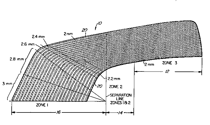
In Figure 4, a further example is shown where the
circular prisms 24 comprise approximately 40% of the
surface of the lens and, in Figure 5, an example is
30 illustrated where the circular prisms 24 comprise
approximately 22% of the total area of the fog section of
the lens 10 and the prisms change in density towards and
into the taillight and stop light areas 14 and 12
respectively. As shown, the prisms have a graduation in
~ 2~7~3
size from 2.2 mm up to 3 mm towards the fog or larger
area of the lens surface.
Turning now to Figures 6 through 11, two methods of
manufacturing a lens are disclosed. In Figure 6, a solid
metal master 30 is contoured as at 32 to provide the
desired curvature and that curvature is machined to
provide the optic elements (for example as shown in
Figure 3a) on the surface thereof and the master is then
drilled as at 32 to receive the desired number of reflex
I pins 34. Suitable means may be utilized, such as a flat
surface, for providing proper alignment of the pins 34 in
the apertures 32.
An electro-form 36 is then made on the surface of
1 15 the metal master, the electro-form taking the
; configuration of the reflex pins and optical elements
from the surface of the master. A single plane lens is
then manufactured by injecting molding a plastic over the
surface of the electro-form, the result being the desired
combination of optical and reflex areas on the surface of
the single plane lens.
In another form of manufacture shown in Figures 7-
10, the reflex pins 38 are located by means of a series
of blade members grooved at suitable locations such as 40
1 25 to locate the hexagonal profiles of the bodies of the
! reflex pins, the outer ends of which have been machined
into a cylindrical form as shown in the bracketed portion
of Figure 8. The blades 42 are manufactured in a
configuration which, when they are secured together with
the pins therebetween, are the equivalent of the sol id
master 30. Using a mold made up from the blades 42 with
the pins 38 secured therein an electro-form 44 is then
made of the pin heads as shown in Figure 10 and a plastic
lens is then manufactured by injecting molding the
plastic as at 46.
~96~703
_ - 12 -
A lens 48 manufactured according to this process is
a single plane lens with the circular prisms 50 located
thereon as shown in Figure 11. Located in juxtaposition
to that lens 48 is an inner lens 52 of optical elements
54 only and the location of these optical elements
relative to the reflex elements or circular prisms 50 is
such that a beam of light 56 from a source 58 thereof is
directed as indicated by the arrows, by the optics 54
through the outer lens 48 between the circular prisms 50.
This is shown in plan view on Figure 3a.
The lens 52 as shown in Figure 11 would be
manufactured by providing a solid metal mold 30 in Figure
6 and grinding the surface of that mold to provide the
desired number, size and location of optic elements
which, when the lens is made therefrom, would provide
the optics 54 as shown in Figure ll.
In an arrangement such as that shown in Figure 11
where two lens surfaces are juxtaposed one to another,
the outer lens 48 would of course be red and the inner
lens 52 would be clear whereas in a single lens design, a
red plastic would be used.
Turning now to Figures 2a and 3a, the location of
the optic elements follows the location of the reflex
elements or circular prisms. As shown in Figure 3a, the
circular prisms 24 overlie optic elements 25 which are
centered between every three circular prisms, when a
pattern such as Figure 3 is used. The optic elements are
circularly ground and, where they overlap, a flat border
area 27 would result.
In Figure 2a, the pattern of the circular prisms 24
is somewhat different with the result that an optic
element 27 is located in the center of every four
circular prisms.
_ - 13 - 206~7Q3
It will be appreciated that, a lens manufactured
according to the invention provides unique visual
appearance having the light transmitted from the interior
light source by the optical elements through those areas
on the lens surface not occupied by the circular prisms
24. Additionally, the reflex prisms are dispensed over
the whole surface of the lens rather than being located
in one particular strip or block as is the conventional
practice.
For regulation purposes, the reflex area of the lens
is measured within a 10 inch diameter circle and for most
applications this area is further limited to the zone
where reflex density is highest. For example, in Figure
1 this would be zone 2. In all other zones of the lens
that carries the interspersed reflex, simulated reflex
elements could be used and which would have an appearance
as close as possible to rear reflex but with no reflex
function. By such an arrangement, there could be a
substantial reduction in the cost of the mold. In such a
case, the effective reflex zone would be produced as
described herein while the simulated reflex zone would be
produced by machining simulated round prisms into a metal
! block, such as steel. This machining could be done by
drilling or by coining or both. With such a method, the
mold for the outer lens would be made of a plurality of
metal elements; electro-forms for the effective reflex
zone, and metal blocks such as steel, machined for the
simulated reflex zones.
While the invention has been described in connection
with a specific embodiment thereof and in a specific use,
various modifications thereof will occur to those skilled
in the art without departing from the spirit and scope of
the invention as set forth in the appended claims.
_ - 14 - 2 ~ ~3~3
The terms and expressions which have been employed
in this specification are used as terms of description
and not of limitations, and there is no intention in the
use of such terms and expressions to exclude any
equivalents of the features shown and described or
portions thereof, but it is recognized that various
modifications are possible within the scope of the
invention claims.