Sélection de la langue

Search

Sommaire du brevet 2060816 

Énoncé de désistement de responsabilité concernant l'information provenant de tiers

Une partie des informations de ce site Web a été fournie par des sources externes. Le gouvernement du Canada n'assume aucune responsabilité concernant la précision, l'actualité ou la fiabilité des informations fournies par les sources externes. Les utilisateurs qui désirent employer cette information devraient consulter directement la source des informations. Le contenu fourni par les sources externes n'est pas assujetti aux exigences sur les langues officielles, la protection des renseignements personnels et l'accessibilité.

Disponibilité de l'Abrégé et des Revendications

L'apparition de différences dans le texte et l'image des Revendications et de l'Abrégé dépend du moment auquel le document est publié. Les textes des Revendications et de l'Abrégé sont affichés :

  • lorsque la demande peut être examinée par le public;
  • lorsque le brevet est émis (délivrance).
(12) Brevet: (11) CA 2060816
(54) Titre français: SOUPAPE DE RETENUE DES LIQUIDES
(54) Titre anglais: FLUID CHECK VALVE
Statut: Périmé et au-delà du délai pour l’annulation
Données bibliographiques
Abrégés

Abrégé français

Clapet de retenue comprenant un ensemble d'obturation installé dans la cavité du corps d'un robinet. L'ensemble d'obturation comporte deux clapets articulés sur une goupille d'articulation, chacune de ses extrémités étant montée dans un élément de retenue appuyé sur la paroi de la cavité. La goupille d'articulation est montée dans des fentes allongées permettant le mouvement des clapets articulés le long de l'axe du robinet. Les éléments de retenue s'insèrent entre le siège du robinet et deux éléments en saillie diamétralement opposés dans la cavité du robinet. Les membres de retenue étant placés entre le siège et les éléments en saillie, des moyens de positionnement maintiennent l'ensemble d'obturation en place.


Abrégé anglais


A fluid check valve has a valve assembly mounted in the bore
of a valve body. The valve assembly has two flap valves mounted
on the hinge pin. The hinge pin is mounted at each end in
holding members which fit against the bore of the valve. The
hinge pin is mounted in elongate slots allowing movement of the
flap valves along the axis of the valve to permit movement of the
flap valves. The holding members fit between the valve seat and
two diametrically opposed projections in the valve bore.
Locating means retain the valve assembly in position with the
holding members between the seat and the projections.

Revendications

Note : Les revendications sont présentées dans la langue officielle dans laquelle elles ont été soumises.


THE EMBODIMENTS OF THE INVENTION IN WHICH AN EXCLUSIVE
PROPERTY OR PRIVILEGE IS CLAIMED ARE DEFINED AS FOLLOWS:
1. A replaceable assembly for insertion in the bore of a fluid check valve,
wherein the bore has an annular seat, the assembly comprising:
a pair of substantially semi-circular valve flapper members adapted to be
positioned in the bore against the annular seat;
a pair of spaced holding members for the valve flapper members, the outer
surface of each holding member being of the same profile as the bore of the check
valve and adapted to be positioned in said bore against said annular seat; and
a hinge pin pivotally mounting said valve flapper members, through holes in
said flapper members, in holes in said holding members, said holes in said flapper
members or said holes in said holding members being elongated parallel to the valve
axis sufficient to allow only the clearing axial movement of said valve flapper
members.
2. A fluid check valve comprising:
a valve body having a bore therethrough;
an annular valve seat in said bore;
a valve flapper assembly positioned in said bore against said seat, said assembly
being as defined in claim 1;
projections in said bore, said holding members extending between said seat and
said projections; and
locating means for retaining the assembly in said bore in a desired alignment.
3. A fluid check valve comprising:
a valve body having a bore therethrough;
an annular valve seat in said bore;
a valve assembly positioned in said bore, said valve assembly comprising;
a pair of substantially semi-circular valve flapper members, a pair of spaced
holding members and an elongate slot in each holding member, the axes of the
elongate slots being parallel to the axis of said bore in said valve body, the outer
surface of each holding member being of the same profile as said bore of said valve
body, a hinge pin pivotally mounting said valve flapper members, said hinge pin
mounted at each end in said elongate slots;
diametrically opposed projections in said bore, said holding

members extending between said seat and said projections; and
locating means for retaining the valve flapper assembly in
said bore with said hinge pin aligned with said projections.
4. A valve as claimed in claim 2 or 3, including a
transverse member extending diametrically across said bore of
said valve body, at said seat, said transverse member aligned
with said projections.
5. A valve as claimed in claim 2 or 3, including stop means
for limiting pivotal movement of said valve members to an open
position.
6. A valve as claimed in claim 2 or 3, including stop means
for limiting pivotal movement of said valve members to an open
position, said stop means comprising a stop pin extending between
said holding members, said stop pin positioned on the side of
said pivot pin remote from said seat.
7. A valve as claimed in claim 3, said locating means
comprising at least one pin in said seat, and at least one bore
in at least one of said holding members, positioned to accept
said pin.
8. A valve as claimed in claim 7, said at least one pin
axially movable in a bore in said seat, a resilient means
biassing said pin to protrude from said bore in said seat.
9. A valve as claimed in claim 8, including an access hole
communicating with said at least one bore in a holding member,
for depression of said pin to permit rotation of said valve
assembly in said valve body.
10. A valve as claimed in claim 2 or 3, including a stop
on each valve member.

Description

Note : Les descriptions sont présentées dans la langue officielle dans laquelle elles ont été soumises.

206~g ~ ~
-- 1 --
FLUID CHECK VALVE
This invention relates to fluid check valves, and in
particular to check valves having two flappers, and sometimes
referred to as a wafer check valve.
In previous types of double flapper-type check valves, hinge
and stop pins are installed through holes which extend through
the wall of the valve body. After installation of the pins, the
holes are sealed by plugs or other means. While initially
effective, there is possibility of leakage from the inside to the
outside past the seals.
Another disadvantage of current designs is that the flappers
are free to move sideways in the valve bore due to the play
needed to permit downstream movement of the flappers, necessary
to avoid interference of the heels of the flappers with the seat
when the flappers rotate to the open position. This movement
causes extra wear on the wall of the flapper hinge or bushing,
depending upon actual design.
One modification made to avoid holes through the wall is to
mount the pins in inserts which fit into cavities machined into
the inner surface of the body wall. These inserts are retained
in place by various means. U.S. Patent 4,694,853 describes and
illustrates the various embodiments in which hinge pins and stop
pins are mounted in inserts positioned in recesses in the body
wall.
Although holes through the body wall are eliminated, and
thus also potential leak paths, the modifications using inserts
are expensive to manufacture and the design can restrict the
particular type of gasket that can be used. Also, thinning of
the wall occurs, which is not desirable.
The present invention avoids the need for holes through the

body wall and also avoids the need to machine recesses in the
body wall. Sideways movement of the valve is also eliminated.
It is possible to eliminate the need for a stop pin.
Broadly, in accordance with the present invention, a fluid
valve comprises a valve body having a bore therethrough, having
an annular seat in the bore. A valve assembly is positioned in
the bore, and comprises a pair of substantially semi-circular
valve members, a pair of spaced holding members having elongate
bores extending axially in the holding members, the outer
surfaces of the holding members of the same profile as the bore
in the valve body. A hinge pin is mounted at each end in the
elongate bores and pivotally mounts the valve members. Two
diametrically opposed projections extend into the bore of the
valve body, the holding members positioned between the seat and
the projections. Locating means position the valve assembly in
the bore with the hinge pin aligned with the projections.
A stop pin may also extend between the holding members,
aligned with the hinge pin, on the side remote from the seat.
The invention will be readily understood by the following
description of certain embodiments, by way of example, in
conjunction with the accompanying drawings, in which:
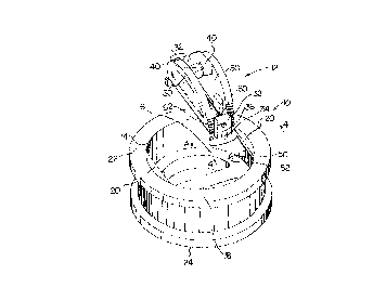
Figure 1 is an exploded perspective view of one form of
valve in accordance with the invention, the valve assembly spaced
from the body, the valve assembly in an open condition;
Figure 2 is a perspective view of the valve assembly of
Figure 1 in a closed condition;
Figure 3 is a perspective view of a holding member, to a
larger scale;

2~;Q8~i
Figure 4 is a cross-section on the line 4-4 of Figure 1.
Figure 1 illustrates, in exploded view, a check valve
comprising a body 10 and a valve assembly 12. The body 10 has
a bore 14, in which is positioned a seat 16. A web 18 extends
diametrically across the bore 14, in the example being at the
level of the seat.
Extending in from the bore 14 are two projections or webs
20, diametrically opposed. The projections 20 are aligned with
the web 18. Gasket surfaces 22 and 24 respectively are at each
end of the valve body. When inserted in a pipe, fluid flow would
normally be upwards in Figure 1, as indicated by arrow A.
The valve assembly 12 is seen more clearly in Figure 2. The
assembly comprises two substantially semi-circular valve members
30, two holding members 32, and a hinge pin 34. In each holding
member 32 is an elongated slot 36, the axis of the slot being
parallel to the axis of the valve body. The hinge pin 34 is
mounted at each end in the elongated slots, and the valve members
30 are mounted on the hinge pin and can pivot from the position
shown in Figure 2 to the position shown in Figure 1. The valve
members are mounted on the hinge pin by bosses 38 and stops 40
can be provided. The outer surfaces 42 of each of the holding
members 32 is of the same profile as that of the surface of the
bore so that they will be a close fit against the wall on the
valve body. Normally the bore will be circular, and the outer
surfaces of the holding members will also be circular.
The valve assembly 12 is positioned in the bore 14 by
holding the valve assembly in its open position, as in Figure 1,
and inserting the assembly into the bore, the valve assembly
rotated so as to clear the projections 20. Once the holding
members are resting on the seat 16, the assembly is rotated to
bring the holding members 32 under the projections 20. The

4 ~6~8~6
holding members are in close fit between the seat 16 and the
projections 20.
To prevent rotation of the valve assembly relative to the
valve body, once assembled, some form of retaining means is
desirable. In the example illustrated, one or more locating pins
50 are positioned in the seating 16. The pins are positioned in
bores 52 and are spring-loaded upward, as by compression springs.
In the holding members 32 bores are formed to receive the pins
50 when the valve assembly is correctly positioned.
Figures 3 and 4 illustrate to a larger scale a holing member
32 and also the positioning of a locating pin and a projection
20. In Figure 3, bores 54 in the bottom surface of the holding
member 32 accept the retaining pins 50. Small diameter access
holes 56 are provided for pushing down the pins when it is
desired to remove a valve assembly. In Figure 4, a bore 52 is
indicated with a pin 50. Also shown is a compression spring 58
which biases the pin upward. At the minimum, only one pin 50 is
required and only one bore 54. For convenience, even with only
one pin, a bore 54 would be provided in each holding member so
as to be independent of the orientation of the valve assembly on
insertion into the valve bore. Two or more pins can be provided,
with suitable bores 54 in the holding members.
If it is desirable, or necessary, to ensure that the valve
members 30 do not move such that one of the valve members moves
past the vertical, a stop pin can be provided. As seen in
Figures 1 and 2, a stop pin 60 is mounted in bore 62 in the
holding member 32.
An alternative provision for limiting the opening of the
valve members, is to form projections on the inner surfaces of
the holding members which the valve members contact on opening,
limiting their travel.

2060~ 1 6
-- 5 --
Instead of spring-loaded pins 50 locating the valve
assembly, other means can be provided. For example, pins could
be inserted through the holding member into bores in the seat.
It would be necessary to ensure that the pins could not fall out
during use.
The elongate bores 36 permit movement of the hinge pin,
along the axis of the valve, to permit the back edges or "heels"
of the valve members to clear the seat as the flapper members
rotate to the open position and also back to the closed position.
In the event that these bores 36 become worn to an extent that
replacement is necessary only the holding members 32 need be
replaced. Axial elongation in any of the hinge pin holes which
allows the valve members 30 to move axially clear of the seat 16,
would be operative. Some or all of this axial clearing movement
of the valve mebers 30 can be provided by axial elongation of the
hinge pin holes in the valve member bosses 38 instead of, or as
well as, the axial elongation of bores 36.

Dessin représentatif
Une figure unique qui représente un dessin illustrant l'invention.
États administratifs

2024-08-01 : Dans le cadre de la transition vers les Brevets de nouvelle génération (BNG), la base de données sur les brevets canadiens (BDBC) contient désormais un Historique d'événement plus détaillé, qui reproduit le Journal des événements de notre nouvelle solution interne.

Veuillez noter que les événements débutant par « Inactive : » se réfèrent à des événements qui ne sont plus utilisés dans notre nouvelle solution interne.

Pour une meilleure compréhension de l'état de la demande ou brevet qui figure sur cette page, la rubrique Mise en garde , et les descriptions de Brevet , Historique d'événement , Taxes périodiques et Historique des paiements devraient être consultées.

Historique d'événement

Description Date
Inactive : CIB de MCD 2006-03-11
Le délai pour l'annulation est expiré 2001-02-12
Lettre envoyée 2000-02-10
Accordé par délivrance 1997-10-28
Inactive : Dem. traitée sur TS dès date d'ent. journal 1997-08-22
Inactive : Renseign. sur l'état - Complets dès date d'ent. journ. 1997-08-22
Préoctroi 1997-07-11
Un avis d'acceptation est envoyé 1997-01-21
Toutes les exigences pour l'examen - jugée conforme 1993-12-02
Exigences pour une requête d'examen - jugée conforme 1993-12-02
Demande publiée (accessible au public) 1993-08-11

Historique d'abandonnement

Il n'y a pas d'historique d'abandonnement

Historique des taxes

Type de taxes Anniversaire Échéance Date payée
Taxe finale - petite 1997-07-11
Annulation de la péremption réputée 1999-02-10 1998-02-10
TM (brevet, 6e anniv.) - petite 1998-02-10 1998-02-10
TM (brevet, 7e anniv.) - petite 1999-02-10 1999-02-10
Annulation de la péremption réputée 1999-02-10 1999-02-10
Titulaires au dossier

Les titulaires actuels et antérieures au dossier sont affichés en ordre alphabétique.

Titulaires actuels au dossier
ROBERT MUDDIMAN
Titulaires antérieures au dossier
S.O.
Les propriétaires antérieurs qui ne figurent pas dans la liste des « Propriétaires au dossier » apparaîtront dans d'autres documents au dossier.
Documents

Pour visionner les fichiers sélectionnés, entrer le code reCAPTCHA :


Pour visualiser une image, cliquer sur un lien dans la colonne description du document. Pour télécharger l'image (les images), cliquer l'une ou plusieurs cases à cocher dans la première colonne et ensuite cliquer sur le bouton "Télécharger sélection en format PDF (archive Zip)" ou le bouton "Télécharger sélection (en un fichier PDF fusionné)".

Liste des documents de brevet publiés et non publiés sur la BDBC .

Si vous avez des difficultés à accéder au contenu, veuillez communiquer avec le Centre de services à la clientèle au 1-866-997-1936, ou envoyer un courriel au Centre de service à la clientèle de l'OPIC.


Description du
Document 
Date
(aaaa-mm-jj) 
Nombre de pages   Taille de l'image (Ko) 
Description 1997-01-20 5 206
Revendications 1997-01-20 2 90
Description 1993-12-03 5 179
Dessins 1993-12-03 2 61
Revendications 1993-12-03 2 52
Abrégé 1993-12-03 1 16
Dessin représentatif 1997-10-26 1 13
Avis concernant la taxe de maintien 2000-03-08 1 178
Taxes 1999-02-09 1 59
Taxes 1998-02-09 1 55
Taxes 1997-02-09 1 58
Taxes 1996-02-06 1 51
Taxes 1995-02-06 1 45
Taxes 1994-02-01 1 43
Correspondance reliée au PCT 1997-07-10 1 58
Courtoisie - Lettre du bureau 1994-01-11 1 46
Correspondance de la poursuite 1993-12-01 1 43
Correspondance de la poursuite 1997-04-06 1 29
Demande de l'examinateur 1993-12-20 1 57
Correspondance de la poursuite 1994-06-12 3 98
Correspondance de la poursuite 1993-11-25 2 57