Sélection de la langue

Search

Sommaire du brevet 2061180 

Énoncé de désistement de responsabilité concernant l'information provenant de tiers

Une partie des informations de ce site Web a été fournie par des sources externes. Le gouvernement du Canada n'assume aucune responsabilité concernant la précision, l'actualité ou la fiabilité des informations fournies par les sources externes. Les utilisateurs qui désirent employer cette information devraient consulter directement la source des informations. Le contenu fourni par les sources externes n'est pas assujetti aux exigences sur les langues officielles, la protection des renseignements personnels et l'accessibilité.

Disponibilité de l'Abrégé et des Revendications

L'apparition de différences dans le texte et l'image des Revendications et de l'Abrégé dépend du moment auquel le document est publié. Les textes des Revendications et de l'Abrégé sont affichés :

  • lorsque la demande peut être examinée par le public;
  • lorsque le brevet est émis (délivrance).
(12) Brevet: (11) CA 2061180
(54) Titre français: CONNECTEUR DE COMPRESSION A CONTACT MULTIPOINT
(54) Titre anglais: MULTIPOINT CONTACT COMPRESSION CONNECTOR
Statut: Périmé et au-delà du délai pour l’annulation
Données bibliographiques
(51) Classification internationale des brevets (CIB):
  • H01R 04/18 (2006.01)
(72) Inventeurs :
  • SCHRADER, GARY E. (Etats-Unis d'Amérique)
  • ANNAN, ROBERT K. (Etats-Unis d'Amérique)
(73) Titulaires :
  • BURNDY CORPORATION
(71) Demandeurs :
  • BURNDY CORPORATION (Etats-Unis d'Amérique)
(74) Agent: BKP GP
(74) Co-agent:
(45) Délivré: 2001-08-14
(22) Date de dépôt: 1992-02-13
(41) Mise à la disponibilité du public: 1992-08-16
Requête d'examen: 1998-10-30
Licence disponible: S.O.
Cédé au domaine public: S.O.
(25) Langue des documents déposés: Anglais

Traité de coopération en matière de brevets (PCT): Non

(30) Données de priorité de la demande:
Numéro de la demande Pays / territoire Date
655,987 (Etats-Unis d'Amérique) 1991-02-15

Abrégés

Abrégé anglais


A multipoint contact compression connector provided
with a plurality of recesses to include a like number of
electrical conductors or cables therein. When placed in an
appropriate crimping device, the connector would contact the
interior die surfaces in at least four points, in such a manner,
so as to secure at least three conductors or cables in place.

Revendications

Note : Les revendications sont présentées dans la langue officielle dans laquelle elles ont été soumises.


The embodiments of the invention in which an exclusive property
or privilege is claimed are defined as follows.
1. An electrical compression connector for connecting
a plurality of conductors or cables comprising:
a connector body of compressible material adapted to
be inserted into a crimping tool having two opposed curved die
surfaces for the compression of the connector, said connector body
provided with a central web portion, said central web portion
provided with at least three recesses extending through the entire
length of said connector body to allow for the inclusion of
conductors within each of the recesses, the periphery of said
connector body provided with at least four distinct, non-continuous
points of contact with curved die surfaces of a crimping tool when
said connector body is inserted within the crimping tool, prior to
crimping; and
wherein when force is applied to the crimping tool,
said connector body would compress, thereby compressing said
connector body around the electrical conductors to be provided in
said recesses and securing the conductors therein.
2. The compression connector in accordance with claim
1 wherein four recesses are provided through the entire length of
said connector body.
3. The compression connector in accordance with claim
2, wherein said connector body is provided with five distinct, non-
continuous points of contact with the curved die surfaces.

Description

Note : Les descriptions sont présentées dans la langue officielle dans laquelle elles ont été soumises.

CA 02061180 2001-O1-19
MULTIPOINT CONTACT COMPRESSION CONNECTOR
BACKGROUND OF THE INVENTION
This invention broadly pertains to electrical
compression connectors for single strand or multistrand
wire or cable conductors. More specifically, the present
invention relates to compression-type electrical
connectors for connecting at least three, and preferably
four, conductors together in an electrical power
distribution system.
Prior art compressible connectors are known in which
more than three wires or cables are included in a single
connector. For example, U.S. Patent 3,354,517 issued to
Levinsky describes a compressible connector having the
provision for connecting four conductors together. This
patent includes closure devices 15,15' which would be
difficult to use in a compression device.
U.S. Patent 3,322,888 issued to Zemels illustrates a
compressible connector having four recesses extending the
length of the connector. However, the two side recesses
are not designed to receive conductors therein.
SLT1~IARY OF THE INVENTION
The present invention overcomes the deficiencies of
the prior art by providing an electrical compression
connector for connecting a plurality of conductors or
cables comprising: a connector body of compressible
material adapted to be inserted into a crimping tool
having two opposed curved die surfaces for the
compression of the connector. This connector body
provided with a central web portion, this central web
portion provided with at least three recesses extending
through the entire length of this connector body to allow

CA 02061180 2001-O1-19
la
for the inclusion of conductors within each of the
recesses, the periphery of this connector body provided
with at least four distinct, non-continuous points of
contact with curved die surfaces of a crimping tool when
this connector body is inserted within the crimping tool,
prior to crimping; and wherein when force is applied to
the crimping tool, this connector body would compress,
thereby compressing said connector body around the
electrical conductors to be provided in this recesses and
securing the conductors therein.
The particular geometry of the connector of the
present invention optimizes and localizes the force
output of the tool to efficiently close the connector, by
providing distinct points of contact to the interior
surfaces of the crimping dies.
BRIEF DESCRIPTION OF THE DRAWINGS
The foregoing and other objects and advantages of
the present invention will be better understood with
reference to the following detailed description of
preferred embodiments thereof, which are illustrated, by
way of example only, in the accompanying drawings,
wherein:
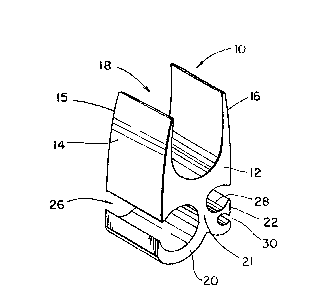
FIG. 1 is a perspective view of a first embodiment
of the present invention;

2
FIG. 2 is a perspective view of a second embodiment of
the present invent: ion;
FIG. 3 is a side elevational view of the second
embodiment of the present invention provided in a crimping tool;
FIG. 4 is a side elevational view of the first
embodiment of the present invention provided in a crimping tool;
'r, r. d
FIG. 5 is a perspective drawing of the second embodi
ment of the present invention after the crimping process has been
completed.
15ETAILE15 DESCIEtIlPTI0~1' OF THE INVEP7TI03~d
A first embodiment of the present invention is shown
with respect to FIGS. 1 and 4. These figures illustrate a
compressible connector 10 having a main body 22 and two substan-
t9.ally paral7.e1 arms 14,16 extending from this main body portion.
The distal portion of arm 14 is curved inwardly at 15. However,
it should be noted that both of the arms 14 and 16 could be
proviUOd without any curved portion. A first recess :18 is formed
between the arr,~,s 14,16 to allow placement of single strand or
multistrand wire conductors or cables therein. A throat portion
21 extends downwardly from the main body 12 and flares out in
several directions to form arm portions 20, 22 and 24. A second
recess 26 is formed between the body portion 12 and the arm 20.
A third recess 28 is formed between the body portion 12 and arm
22, and a fourth recess portion 30 is formed between arm 22 and
arm 24. As a minimum, recesses 18 and 40 of Figures 1 and 2 must
have appropriate conductors located within, while any one of
recesses 26,28,30 of Figure 1 and 46,47,48 of Figure 2 must be
filled. Variously sized wires or conductors can be provided
within each of these recess portions.
When placed in a standard crimping tool having die
surfaces 64 and 66, the connector 10 would come into contact with
the interior surfaces of the dies at points 68, 70, 72 and 74.
As a compressive force is applied, these points will come into
contact with the die surfaces, and the conductors provided in
recesses 26, 28 and 30 will receive direct compressive loads due

3
to t.l-~e unique geometric relationship between the connector and
the Gie. After the crimping process is terminated, conductors
provided in these recesses would be secured in place.
FIGS. 2, 3 and 5 illustrate a second embodiment of the
present invention. This embodiment depicts a compressible
eonn~~ctor 3? provided with a main body portion 34 and two
upwardly extending, substantially parallel leg portions 36,38.
A first recess 40 is provided between the leg portions 36,38.
A second rece::s 46 is provided in the central portion 34 below
the leg 38, thereby forming a ridge 44. Similarly, a third
recess 48 is formed in the body portion 34 below the leg 36,
thereby also creating a ridge portion 42. A curved leg 45
extends from the body portion 34 to create a recess portion 47
below and between the recess portions 46 and 48. All of the
recess portions 40, 46, 47 and 48 can receive various sized
electrical conductors and cables therein.
When pl«ced in a crimping device having die surfaces
50 and 52, the connector 32 would contact the interior surfaces
of the dies at points 54, 56, 58, 60 and 62. When compressive
force is applied to this connector, it will initially contact at
these points 54, 56, 58, 60 and 62. The application of this
force would then allow conductors 72, 74, 76 and 78 to be secured
and encircled by the body of the connector as illustrated in FIG.
5.
TY~e connector of the present invention can be manufac- -
tured from tin-plated copper, aluminum or similar metallic
materials which would appropriately deform when pressure is
applied in si:andard mechanical, hydraulic and pneumatic crimping
devices.
While the present invention has been illustrated in
connection with two preferred embodiments, it should be under-
stood that many variations will occur to those skilled in the
art. and that other types of compression connector geornetries may
be utilized.

Dessin représentatif
Une figure unique qui représente un dessin illustrant l'invention.
États administratifs

2024-08-01 : Dans le cadre de la transition vers les Brevets de nouvelle génération (BNG), la base de données sur les brevets canadiens (BDBC) contient désormais un Historique d'événement plus détaillé, qui reproduit le Journal des événements de notre nouvelle solution interne.

Veuillez noter que les événements débutant par « Inactive : » se réfèrent à des événements qui ne sont plus utilisés dans notre nouvelle solution interne.

Pour une meilleure compréhension de l'état de la demande ou brevet qui figure sur cette page, la rubrique Mise en garde , et les descriptions de Brevet , Historique d'événement , Taxes périodiques et Historique des paiements devraient être consultées.

Historique d'événement

Description Date
Le délai pour l'annulation est expiré 2004-02-13
Lettre envoyée 2003-02-13
Inactive : Lettre officielle 2003-01-03
Exigences relatives à la révocation de la nomination d'un agent - jugée conforme 2003-01-03
Exigences relatives à la nomination d'un agent - jugée conforme 2003-01-03
Inactive : Lettre officielle 2003-01-03
Demande visant la révocation de la nomination d'un agent 2002-11-12
Demande visant la nomination d'un agent 2002-11-12
Accordé par délivrance 2001-08-14
Inactive : Page couverture publiée 2001-08-13
Préoctroi 2001-05-10
Inactive : Taxe finale reçue 2001-05-10
Inactive : Taxe de modif. après accept. traitée 2001-01-19
Modification après acceptation reçue 2001-01-19
Lettre envoyée 2000-11-29
Un avis d'acceptation est envoyé 2000-11-29
Inactive : Approuvée aux fins d'acceptation (AFA) 2000-11-14
Modification reçue - modification volontaire 1999-06-14
Inactive : Renseign. sur l'état - Complets dès date d'ent. journ. 1998-11-19
Lettre envoyée 1998-11-19
Inactive : Dem. traitée sur TS dès date d'ent. journal 1998-11-19
Toutes les exigences pour l'examen - jugée conforme 1998-10-30
Exigences pour une requête d'examen - jugée conforme 1998-10-30
Demande publiée (accessible au public) 1992-08-16

Historique d'abandonnement

Il n'y a pas d'historique d'abandonnement

Taxes périodiques

Le dernier paiement a été reçu le 2001-01-05

Avis : Si le paiement en totalité n'a pas été reçu au plus tard à la date indiquée, une taxe supplémentaire peut être imposée, soit une des taxes suivantes :

  • taxe de rétablissement ;
  • taxe pour paiement en souffrance ; ou
  • taxe additionnelle pour le renversement d'une péremption réputée.

Les taxes sur les brevets sont ajustées au 1er janvier de chaque année. Les montants ci-dessus sont les montants actuels s'ils sont reçus au plus tard le 31 décembre de l'année en cours.
Veuillez vous référer à la page web des taxes sur les brevets de l'OPIC pour voir tous les montants actuels des taxes.

Historique des taxes

Type de taxes Anniversaire Échéance Date payée
TM (demande, 6e anniv.) - générale 06 1998-02-13 1998-01-16
Requête d'examen - générale 1998-10-30
TM (demande, 7e anniv.) - générale 07 1999-02-15 1999-01-13
TM (demande, 8e anniv.) - générale 08 2000-02-14 2000-01-18
TM (demande, 9e anniv.) - générale 09 2001-02-13 2001-01-05
2001-01-19
Taxe finale - générale 2001-05-10
TM (brevet, 10e anniv.) - générale 2002-02-13 2002-01-31
Titulaires au dossier

Les titulaires actuels et antérieures au dossier sont affichés en ordre alphabétique.

Titulaires actuels au dossier
BURNDY CORPORATION
Titulaires antérieures au dossier
GARY E. SCHRADER
ROBERT K. ANNAN
Les propriétaires antérieurs qui ne figurent pas dans la liste des « Propriétaires au dossier » apparaîtront dans d'autres documents au dossier.
Documents

Pour visionner les fichiers sélectionnés, entrer le code reCAPTCHA :


Pour visualiser une image, cliquer sur un lien dans la colonne description du document. Pour télécharger l'image (les images), cliquer l'une ou plusieurs cases à cocher dans la première colonne et ensuite cliquer sur le bouton "Télécharger sélection en format PDF (archive Zip)" ou le bouton "Télécharger sélection (en un fichier PDF fusionné)".

Liste des documents de brevet publiés et non publiés sur la BDBC .

Si vous avez des difficultés à accéder au contenu, veuillez communiquer avec le Centre de services à la clientèle au 1-866-997-1936, ou envoyer un courriel au Centre de service à la clientèle de l'OPIC.


Description du
Document 
Date
(aaaa-mm-jj) 
Nombre de pages   Taille de l'image (Ko) 
Revendications 1993-11-26 1 35
Abrégé 1993-11-26 1 10
Dessins 1993-11-26 3 39
Description 1993-11-26 3 137
Description 2001-01-18 4 160
Dessin représentatif 1999-07-07 1 5
Dessin représentatif 2001-08-01 1 7
Rappel - requête d'examen 1998-10-21 1 116
Accusé de réception de la requête d'examen 1998-11-18 1 177
Avis du commissaire - Demande jugée acceptable 2000-11-28 1 165
Avis concernant la taxe de maintien 2003-03-12 1 174
Correspondance 2002-11-11 3 93
Correspondance 2003-01-02 1 14
Correspondance 2003-01-02 1 20
Taxes 2002-01-30 1 38
Correspondance 2001-05-09 1 34
Correspondance 1998-07-07 4 109
Taxes 1999-01-12 1 48
Taxes 2000-01-17 1 41
Taxes 2001-01-04 1 35
Taxes 1997-01-09 1 43
Taxes 1996-01-21 1 49
Taxes 1995-01-11 1 53
Taxes 1994-01-27 1 47