Note : Les descriptions sont présentées dans la langue officielle dans laquelle elles ont été soumises.
WO91/00146 2 0 6 2 8 2 5 PCT/US90/02866
METHOD AND APPARATUS FOR
SORTING ARTICLES WITH SMALL
DENSITY DIFFERENCES
UTILIZING A FLOTATION STREAM
BACKGROUND OF THE INVENTION
1. Field of the Invention
The present invention relates to methods and apparatus
for separating mixtures of articles of different densities,
and more particularly to such methods and apparatus as are
applicable to the sorting of articles such as, for example,
agricultural or other products having small density
differences into several density groups by utilizing a
flotation stream.
2. Backqround Art
The use of density variation as a means of separating
mixtures of articles is widespread. In agriculture, the
separation and sorting of produce on this basis is accom-
plished using both wet and dry methods.
Wet methods use a Iiquid as a medium with which to
separate denser articles, which sink in the given liquid,
from the lighter ones that will float thereupon. Dry
methods of sorting employ a form of pneumatic separation
based on a combination of differing densities and differing
aerodynamic properties associated with the components to be
sorted.
In one type of dry method, a gas, such as air, is
forced upwardly through a moving bed of the mixture to be
separated. This gas flow through the interstices of the
particles of the mixture tends to disengage the particles
from each other, permitting the gas flow to support at
least some of the weight thereof. As a result, the bed of
'~
WO91/00146 PCT/US90/02866
2 o~282~ 2
the mixture resembles a liquid of high viscosity, and the
particles of the mixture are freed to a degree to migrate
within the bed under the influence of physical forces such
as gravity that might tend to induce separation among the
constituent components.
The separation that occurs when a mixture to be
separated is itself fluidized is not one that results
exclusively due to differing density among the components
of the mixture. Instead, the aerodynamic properties of the
particles of the mixture also have a substantial impact
upon the rate and quality of the separation that results.
The upward flow of gas through the mixture will tend to
draw with it the less compact particles of the mixture,
regardless of their density.
In one type of device the fluidization of such a
mixture may be effected as it passes down an inclined
trough. At the discharge end of the trough the mixture of
the materials will become somewhat stratified according to
the combined density and aerodynamic property of the
component particles. Nevertheless, such a device has
several inherent drawbacks which render it less than
optimally desirable in relation to the broad range of
circumstances in which agriculture separators of the dry
variety are nevertheless desirable.
First, separators which pneumatically fluidize the
actual mixture to be separated have limited separation
effectiveness. While the upper and lower layers of the
stratified mixture discharged from the end of the separator
trough may be relatively pure, the layers intermediate
thereto continue to comprise a mixture of particles of both
densities. This problem is ameliorated to some degree by
horizontally narrowing the separation between the vertical
walls of the trough in the vicinity of its discharge end.
This has the effect of increasing the depth of the flow at
WO91/00146 2 ~ ~ 2 8 2 5 PCT/US90/02866
.
3 _ _
that point, affording more vertical distance between the
separated top and bottom layers of the mixture. Still, at
some point between these two extreme layers, the two
materials of differing densities remain substantially
intermixed in an interfaced layer. This fact precludes the
achievement of optimal separation effectiveness.
A second, more profound drawback of separation methods
in which the mixture to be separated is itself
pneumatically fluidized arises from the fact that
fluidization of the mixture is not practical if the
particles of the mixture have diameters greater than
approximately three or four millimeters. Thus, such
methods are effective only in separating small products,
such as grain cereal. They cannot be used to separate or
sort large produce.
Toward that end, resort has been made to a second type
of dry method which is based on the use of fluidized beds
which are constituted of a material other than the mixture
to be separated. For the purpose of separating mixtures of
larger solid bodies of differing densities, a fluidized bed
created from such a fluidization medium behaves in a manner
analogous to a liquid, but without wetting the articles of
the mixture it is used to separate. Pieces of solid
material less dense than the apparent density of the
fluidized bed will act as a "float fraction" which will
float on the surface of the bed. Pieces of solid material
which are more dense than the apparent density of the
fluidized bed will, on the other hand, act as a "sink
fraction" of the mixture which will sink to the bottom of
the bed.
For separation to occur, the apparent density of the
fluidized bed must be intermediate the densities of the
float and sink fracticns of the mixture. Additionally, the
particle size of the fluidization medium must be smaller by
WO91/00146 PCT/US90/02866 ~
~2825 4
several orders of magnitude than the size of the bodies
contained in the mixture that is to be separated.
The use of a fluidization medium other than the
mixture to be separated advantageously reduces the
influence on the process of other separation factors, such
as aerodynamic characteristics, and reduces the process to
one in which separation is accomplished substantially on
the basis of differing density only. In addition, the
presence of a layer of fluidization medium intermediate the
float fraction of the mixture on top of the fluidized bed
and the sink fraction of the mixture at the bottom thereof
permits a clean separation of the float and sink fractions.
This is accomplished by separating the upper portion of the
fluidized bed with the float fraction entrained therein
from the lower portion thereof having the sink fraction
entrained therein. Thereafter the two components are
cleaned independently to remove any fluidization medium,
and close to one hundred percent separation effectiveness
between the float and sink fractions of the mixture can be
achieved.
While this type of dry method works well for many
applications, it still has some limitations. For example,
most of the available methods, except a few wet methods,
are aimed at separating products with large differences in
density (such as clods and stones from potatoes, or plastic
particles from copper particles, etc.). Meanwhile, a large
variety of sorting applications for various types of
products exists wherein the products to be sorted have only
small differences in density. Mixtures of such products
are commonly found, for example, in agriculture.
Most agricultural products such as fruits and
vegetables do not have uniform quality and they do not
uniformly mature. Postharvest qu~lity sorting is thus
WO91/00146 ~ 0 6 2 8 2 5 PCT/US90/02866
required to supply reliable and uniform quality in the
market place.
Some of the used techni ques for quality sorting are
specific to the kinds of produce for which they were
developed. In addition, there are no viable methods for
sorting numerous other products.
Density may be the most direct and consistent index of
maturity and other quality changes. When quality changes
are not manifest in external changes, such as differences
in size, weight, color, etc., quality sorting with current
technology is ineffective. Density may be the sole
criterion to permit opportunities for quality sorting in
such circumstances. However, quality sorting based on
density differences has found limited success in commercial
15 applications for several reasons.
Density changes due to quality transformations in
agricultural commodities usually are very small (in the
range of 0.02 - 0.04 g/cm3). Effectively detecting and
sorting products having these small differences appears to
20 be possible only in a highly controlled density sorting
process. Current density sorting techniques which use
liquids such as brine solutions or solutions of alcohol in
water to sort sink and float fractions require very close
control of the density of such solutions so as to maintain
25 the density intermediate that of the sink and float
fractions. This is difficult, particularly as such
solutions tend to become contaminated with foreign
materials, which affects the solution's density. Thus,
frequent changing of the solution may be required, as is
30 preconditioning and post washing operations to reduce
contamination and also to remove such liquids from the
produce. These operations often deteriorate product
quality and storageability. Furthermore, such liquids are
expensive, and they may present fire and social hazards
WO91/00146 ~ 0 ~ 8 2 5 PCT/US90/02866
when used in large quantities. Some commodities such as
peas and blueberries need preliminary prewetting to remove
air bubbles. Others, such as peanuts, walnuts, and pecans
generally can't be processed in liquids because the
absorption of the liquids adversely change mealiness
properties. Furthermore, sorting frequently requires
grading into three or more categories, which in turn may
require several liquid changes.
On the other hand, dry methods of the type noted above
are generally limited to sorting mixtures of products
wherein there are relatively large density differences
between the float and sink fractions. When differences in
densities of the products to be sorted are small, such as
in the range of differences on the order of 0.02 g/cm3, the
density of the fluidized bed, which as noted must be
intermediate the sink and float fractions, should differ by
only 0.0l g/cm3 from the densities of the products.
Maintaining a fluidized bed within such parameters is
technically difficult to achieve. Accordingly, what is
needed is a method and apparatus for sorting articles with
small density differences which can be implemented
utilizing either wet or dry fluidized bed techniques and
which eliminates many of the above-noted difficulties.
Such an apparatus and method are described and claimed
herein
SUMMARY OF THE INVENTION
In accordance with the invention as embodied and
broadly described herein, a separator is provided in which
a flotation stream continuously flows through a trough and
is used to effect the separation of a mixture of float
fraction articles having small density differences into
several groups.
W O 91/00146 ~ 2as2825 PC~r/US90/02866
.
Each density group contained in the mixture of
articles to be separated is introduced at the head of the
flotation stream at a selected depth, for example, by
5 dropping the mixture of articles into the stream from a
predetermined height, or by introducing the entire mixture
of articles into the stream at the same selected depth, as
for example through a chute which has an outlet that opens
into the flotation stream at the selected depth. In one
embodiment of the invention the flotation stream may be,
for example, a fluidized bed of the type which is created
by forcing a gas such as air upwardly through a moving bed
of fluidi~ation medium such as sand as the sand flows
through the trough. In another embodiment of the
invention, the flotation stream may be formed from a
liquid. In either case, the velocity of the flotation
stream may be adjustably controlled and the density of the
flotation stream is maintained at an essentially uniform
value which is greater than the density of any of the float
fraction articles.
In accordance with the method and apparatus of the
invention, once the mixture of articles is introduced at
the selected depth for each density group into the
flotation stream near the head of the stream, to the extent
that the density of the flotation stream is greater than
25 the density of the articles, the articles of lesser density
(e.q., the float fraction) will begin to ascend toward the
top of the flotation stream while at the same time the
articles are carried down stream by virtue of the velocity
of the flotation stream. The time of ascension will vary
30 based on the differing densities of the float fraction
articles contained in the mixture to be separated.
Accordingly, float fraction articles having a greater
density will be carried further downstream whereas float
fraction articles within the mixture having less density
WO91/00146 PCT/US90/02866
~QB2~ 8
will ascend to the top of the stream at a point further
upstream than the more dense articles, thereby affecting a
spacial separation of the float fraction articles based on
their differing densities.
To the extent that articles are contained with the
mixture which have a density greater than that of the
flotation stream, those articles will tend to act as a sink
fraction which will not ascend toward the top of the
stream. Accordingly, separation of the mixture into
various groups may result not only based on the fact that
the mixture contains sink and float fractions, but
importantly, with respect to the float fraction of the
mixture which ascends to the top of the stream, there will
also be a spacial separation into various groups based only
on the differing densities of those groups.
Advantageously, this method and apparatus will permit
effective separation of the mixture of articles, even
though the articles have only very small density
differences, as for example, where the differences are on
the order of 0.02 g/cm3, and eliminates the need in many
cases for maintaining the density of the flotation stream
at an intermediate value.
By increasing the velocity of the flotation stream the
degree of spacial separation affected as the articles
ascend to the top of the stream can be increased, or in the
alternative, the same result can be obtained by introducing
the articles into the flotation stream at a greater depth,
as for example by dropping them at a greater height into
the head of the stream. Baffles can also be placed at the
top of the stream to assist in the separation of the
various groups and also to form compartments from which the
sorted groups may be discharged from the flotation stream.
WO91/00146 2 0 6 2 8~ 5 PCT/US90/02866
BRIEF DESCRIPTION OF THE DRAWINGS
A more particular description of the invention briefly
summarized above will be rendered by reference to the
specific embodiments thereof which are illustrated in the
appended drawings, in which like parts are designated by
like numerals. Understanding that these drawings depict
only typical embodiments of the invention as represented,
for example, by the currently understood best mode for
practicing the invention, the drawings are there~ore not to
be considered limiting of its scope. The invention will
thus be described with additional specificity and detail
through the use of the following drawings in which:
Figure l is a perspective view of one embodiment of a
separator incorporating the teachings of the present
invention;
Figure 2 is an elevation view in partial cross-section
of the embodiment of the separator illustrated in Figure l
taken along section line 2-2 shown therein;
Figure 3 is a perspective view of the trough of the
separator of Figure 2, with portions thereof shown cut-away
to reveal further detail;
Figure 4 is a cross-sectional elevational view of the
trough of Figure 3 taken along section line 4-4 shown
therein;
Fig. 5 is a transverse cross-sectional view of the
trough of Figure 3 taken along section line 5-5 shown
therein;
Figure 6 is a detailed perspective view of an
alternate embodiment of the restriction means of the
30 present invention;
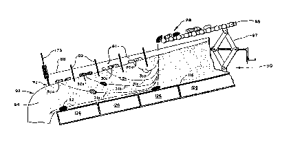
Figure 7 is a schematic illustration which depicts one
method in which the teachings of the present invention may
be implemented in a separator utilizing a flotation stream
formed from a fluidized bed;
WO91/00146 2 ~ 6 ~ 8 2 ~ PCT/US90/02866 ~
Figure 8 is a transverse cross-sectional view of the
trough of Figure 2 taken along section line 8-8 shown
therein;
Figure 9 is a cross-sectional view illustrating an
alternative method and apparatus for discharging articles
from the flotation stream once they have been separated
into groups based on different densities; and
Figure 10 is a schematic illustration of another
embodiment of a separator incorporating the teachings of
the present invention, depicting utilization of a flotation
stream formed from a liquid and also showing an alternative
method for introducing the mixture of articles into the
flotation stream.
DESCRIPTION OF THE PREFERRED EMBODIMENTS
One presently preferred embodiment of a separator
incorporating the teachings of the present invention may be
understood by reference to Figure 1. There a fluidized bed
separator generally designated at 10 can be seen to
comprise a frame generally designated at 12 and supported
and rendered mobile on tires 14.
One end of frame 12 terminates in a cantilevered
triangular platform generally designated at 16 upon which
is supported a columnar enclosure 18, the function of which
25 will be explained below. The apex of triangular support
platform 16 remote from separator lO includes a hitching
mechanism 20 by which separator 10 may be attached to a
vehicle and drawn from one work site to another on tires
14. For convenience the end of separator 10 that includes
triangular support platform 16 will be referred to
hereinafter as the "front end" of separator 10, as it
precedes the other portions thereof when separator 10 is
being towed by a vehicle. Adjacent hitching mechanism 20,
frame 12 also includes an adjustable footing generally
WO91/00146 2 0; ~ 2`8 2 ~ `~ PCT/US90/02866
.
11
designated at 22 for supporting the front end of separator
10 and leveling frame 12 when hitching mechanism 20 is not
connected to a towing vehicle.
The end of separator 10 opposite from the front end
thereof terminates in a cantilevered rectangular support
platform generally designated at 24. In one aspect of the
invention, separator 10 comprises a mixture feed means for
supplying a mixture of articles to be separated to a
channelization means, as described further below. In the
illustrated embodiment, the mixture feed means is comprised
in part of a mixture receiving conveyor 26 which receives
mixtures of articles to be processed by separator 10 and
advances the mixture in the direction indicated by arrow A.
For the sake of simplicity the power source and drive
mechanism for mixture receiving conveyor 26, and other
conveyors presently to be described, have not been depicted
in the figures. Similarly, some supporting structure, such
as frames, braces, and adjustment mechanisms for various
functional components of separator 10 have been eliminated
20 to simplify the drawing.
A typical mixture 28 (see Figures 2 and 7) for
processing by separator 10 is received on mixture receiving
conveyor 26. Mixture 28 includes a float fraction 30 of
articles 30a-30d having small density differences but all
25 of which are less than the density of the flotation stream.
Mixture 28 may also contain a sink fraction 32 of articles
having a density that is greater than that of the flotation
stream. The various articles 30, 32 of mixture 28 are
preferably sized before being introduced onto receiving
30 conveyor 26 so that the articles 30, 32 are generally of a
uniform size. Sizing can be accomplished using a variety
of methods and devices which are known in the art.
W O 9l/00146 206 ? 8 ~ ~ 12 PC~r/US90/02866
Adjacent mixture receiving conveyor 2 6 and supported
on rectangular support frame 24 is a section of flooring 34
upon which a worker may stand and, by observing mixture 28
5 passing on mixture receiving conveyor 26, remove therefrom
any articles not properly sized or otherwise obviously
defective.
The articles 30, 32 on mixture receiving conveyor 26
arrive in a cleaning enclosure generally designated at 36
for gentle agitation and advancement in the direction
indicated by arrow B on a floor of individually driven
spaced-apart cleaning rollers 38. Cleaning rollers 38,
which also comprise part of the mixture feed means, may
each advantageously be provided in a known manner with a
plurality of short radially extending paddle-like
projections which lift and tumble the articles of mixture
28 as cleaning rollers 38 are rotated. This initial
processing of mixture 28 permits fine contaminants, such as
sand, gravel, and dust, which would otherwise form a part
of sink fraction 32 of mixture 28, to fall downwardly out
of cleaning enclosure 3 6 through the separations between
adjacent cleaning rollers 38, where they come to rest and
are carried away by a particle conveyor (not shown for
purposes of simplifying the drawing). The preliminary
cleaning of mixture 28 to remove fine contaminants thus
reduces the amount of fine dust that eventually becomes
mixed with the flotation stream employed in separator 10.
In addition to supporting the mechanisms which effect
the above-described preliminary cleaning, rectangular
support platform 24 upholds other conveyors which will be
described presently. For convenience the end of separator
10 that includes rectangular support platform 24 will be
referred to hereinafter as the "back end" of separator 10,
as it follows the other portions thereof when separator 10
is being towed by a vehicle.
WO91/00146 Z 0 6 ~ 8 2 5 PCT/US90/02866
13
Referring still to Figure 1, it can be seen that frame
12 between triangular support platform 16 at the front end
of separator 10 and rectangular support platform 24 at the
5 back end thereof is formed into a box-like framework
designated at 46 within which the actual separation of
mixture 28 is effected using fluidized bed principles.
Extending a substantial distance above the top of box-
like framework 46 is an air intake stack designated at 48
through which to draw ambient air into the pneumatic system
of separator 10. The height of open upper end 50 of air
intake stack 48 enables air blowers 52 communicating with
the bottom end 54 thereof to draw air in the direction
shown by arrows F into that pneumatic system which is
relatively free of dust generated by separator 10 itself.
Air from air blowers 52 passes through ducting 56 and
flexible piping 58 to columnar enclosure 18 as shown by
arrows G.
Further processing of the air utilized in the pneuma-
tic system of separator 10 will be described subsequently,
but it should be noted that the placement of air blowers s2
at the intake end of the pneumatic system of separator 10
causes all air passing therein, with the exception only of
air moving through air intake stack 48, to be in a state of
positive pressure. This advantageously precludes entry
into the pneumatic system of airborne dust at any point
downstream from air blowers 52. Accordingly, pneumatic
systems passageways, such as ducting 56 and flexible piping
58, need not be absolutely air tight in order to preserve
the purity of the air therein. Any cracks or small open-
ings in such passageways will inherently permit the escapeof air outflow from the pneumatic system. To facilitate
the transportation of separator 10 and to reduce the chance
of wind damage to air intake stack 48 when separator 10 is
not in use, the bottom 54 of air intake stack 48 is
= ~
WO91/00146 ~ PCT/US90/02866
2~)~;'2g2~
14
provided with a hinge mechanism 60 which permits air intake
stack 48 to be lowered against the top of box-like frame-
work 46 as shown by the dashed lines in Figure 2.
The space interior to box-like framework 46 toward the
back end of separator 10 is occupied by a medium
recirculation means for supplying fluidization medium
collected at an output of the channelization means back to
the input thereof. By way of example, the medium
recirculation means is comprised of a horizontally disposed
recirculation. drum 64 supported for rotation about the
longitudinal axis thereof on several pairs of drive wheels
66 mounted in bearings 68 on each side of recirculation
drum 64, together with the additional structure described
below which together with drum 64 provide the stated
function of the medium recirculation means.
The axles of drive wheels 66 on each side of
recirculation drum 64 are interconnected by shafts 70 and
chain couplings 72. In this manner all drive wheels 66 on
one side of recirculation drum 64 will flexibly support the
weight thereof and nevertheless be driven together by a
single hydraulic motor 74 in order to rotate recirculation
drum 64. The two hydraulic motors 74 on each side of
recirculation drum 64 are connected in parallel with each
other and powered by a single conventional hydraulic pump
(not shown), and together serve as a drive means for
turning each of the drive wheels 66 in a common direction
to rotate the recirculation drum 64. This arrangement
permits variation in the speed at which recirculation drum
64 is rotated and automatically compensates for the uneven
loading of the two sides of recirculation drum 64 which is
encountered in normal operation of separator 10.
To enhance the traction between drive wheels 66 and
recirculation drum 64, the exterior of the latter is
provided at the portions bearing against drive wheels 66
WO91/00146 2 ~ ~ 2 8 2 15 t ~ ~ PCT/US90/02866
with traction track 76. Recirculation drum 64 is retained
in position supported on drive wheel 66 by sets of idler
wheels 78 which contact the outer surface of recirculation
5 drum 64 above and on each side of the longitudinal axis
thereof at traction tracks 76. Longitudinal displacement
of recirculation drum 64 is precluded by bearing wheels 80
thereof which engage lateral annular end surfaces 82 at
each end of recirculation drum 64. For the purpose of
separator 10, recirculation drum 64 is rendered capable of
rotation at a speed of from zero to six revolutions per
minute, and typically at about four revolutions per minute.
The interior surface of recirculation drum 64 is
provided with a continuous plurality of transport pockets
200 (see Figure 1). As seen in Figures 1 and 2 taken
together, fluidization medium 96 emerging from output end
92 of trough 88 falls to the bottom of recirculation drum
64 filling transport pockets 200. By means of rotation
recirculation drum 64 lifts the fluidization medium 96
upwardly for unloading into hopper 152. Hopper 152 in
combination with feed conveyor 150 functions as a medium
translation means for receiving fluidization medium 96
unloaded from transport pockets 200 and transferring such
fluidization medium 96 to input end 90 of trough 88.
Use of a recirculation means such as that of the
25 present invention results in a sorter 10 which is shorter
laterally by approximately 30% than a sorter employing
conventional conveyors to lift fluidization medium back
into the channelization means of the apparatus. In addi-
tion, recirculation drum 64 provides a cover protecting the
fluidization medium therein from water, such as rain and
dew, when the device is not in use. As substantially all
separating and cleaning occurs within recirculation drum 64
the dispersal cf dust from that process is substantially
reduced by the enclosure afforded by recirculation drum 64.
WO91/00146 Z 0 6~ 8 2 5 PCT/US90/02866
16
Such a recirculation means has also been found to require
less fluidization medium than corresponding known fluidized
bed separators.
The space within box-like framework 46 at the front
end of separator 10 encloses an operator control platform
84 from which vantage point the functioning of separator 10
can be observed and controlled. Other equipment is
enclosed in box-like framework 46 but will be described in
relation to other of the figures.
As best understood in relation to Figure 2, separator
10 includes a channelization means for establishing a bed
through which the flotation stream continuously flows. In
the illustrated embodiment, the channelization means is in
the form of an inclined trough 88 having an elevated input
end 90 and an output end 92. Trough 88 contains a
fluidized bed 94, enabling it to flow under the influence
of gravity from input end 90 to output end 92.
Fluidization bed 94 is comprised of a fluidization medium
96, such as sand, which is supplied to input end 90 of
trough 88 in the manner to be described above. Mixture 28
from cleaning enclosure 36 is transported upon mixture
conveyor 98, which further comprises part of the mixture
feed means, in the direction shown by arrow H also to input
end 90 of trough 88 for entrainment in fluidized bed 94.
The creation of fluidized bed 94 from fluidization
medium 96 occurs as a result of forcing air upwardly
through the fluidization medium 96 in trough 88 by a
pneumatic means better understood in relation to Figures 3,
4, 5, and 5A taken together. As seen therein, trough 88
includes sidewalls 110, 112 which narrow toward output end
92 of trough 88. Input end 90 of trough 88 is formed into
an inclined end wall 114. The bottom of trough 88 com-
prises an A ir distribution plate 116 which may be a high
density perforated polyethylene plate or porous metal
WO91/00146 2 0 6 2 82 5 ~ PCT/US90/02866
17
sheet. For the~purposes of separator 10, a gas
distribution plate 116 having an average opening of 30
microns and a flow rate of 50 standard cubic feet per
minute has proven satisfactory. Ultimately, ambient air
taken in through intake stack 48 (see Figure 2) and
pretreated in a manner to be described in detail hereafter
is directed through air distribution plate 116 and forced
upwardly through the layer of fluidization medium 96
supported in trough 88.
Air for this purpose enters a series of chambers 126
(see Figure 4~ below trough 88 and air distribution plate
116 through an orifice 118 shown in Figures 4 and 5 in the
bottom wall of an air receiving chamber 120 beneath
inclined end wall 114. The air then divides and passes on
15 either side of trough 88 through rectangular air plenums
122, 124 which extend the full length of trough 88 on
opposite sides thereof (see Figure 5). Below air
distribution plate 116 are a series of gas pressure
chambers 126 which each open into one or the other of air
20 plenums 122, 124 through a plurality of circular air intake
openings 128. Air under pressure in air plenums 122, 124
thus passes through air intake openings 128 into gas
pressure chambers 126 and is forced upwardly through air
distribution plate 116 and fluidization medium 96
25 thereabove to create fluidized bed 94.
Each set of air intake openings 128 is adjustably
occludable by a pivoted air pressure control plate 130 (see
Figure 3) which may be raised and lowered by a control
cable 132 attached to one end thereof. Ultimately such
30 occlusion impacts the effective density of fluidized bed 94
above each individual air pressure chamber 126. Partially
covering intake openings 128 by lowering the pressure
control plate 130 reduces the air pressure in the
associated air pressure chamber 126 in relation to that
WO91/00146 2 0 6 2 g 2 5 PCT/US90/02866 ~
18
existing in air plenums 122, 124. Thus, air intake open-
ings 128 in combination with air pressure control plates
130 serve as air pressure reducing valves for each of air
pressure chambers 126.
The narrowing of sidewalls 110, 112 toward the output
end 92 of trough 88 causes the depth of fluidized bed 94 to
increase in the direction of its flow. Nevertheless, it
may be desirable for optimally efficient separation of
mixture 28 into its consistent groups that the effective
density of fluidized bed 94 be held essentially constant,
regardless of any variation in its depth, particularly if
mixture 28 includes a sink fraction 32. Increasing the
depth of the fluidized bed 94 also enhances separation of
any sink fraction 32.
A shallow fluidized bed requires less air flow to
achieve the same effective density than does a deeper one.
Decreased air flow in the shallower portions of fluidized
bed 94 is therefore utilized to maintain a uniform density
therein. The air pressure in each of air pressure chambers
20 126 immediately below air distribution plate 116 is indiv-
idually adjusted toward that end by manipulating air
pressure plates 130. The air in air pressure chambers 126
is thereby graduated so that the pressure of the air in
each decreases corresponding to the distance of each air
25 pressure chamber 126 along distribution plate 116 from
output end 92 of trough 88. This ad~ustment of air pres-
sure is intended to correspond roughly to the variation in
the depth of fluidized bed 94 along the length of trough
88.
Control cables 132 for manipulation of air control
plate 130 terminate at control platform 84 (see Figure 1)
to permit operation of separator 10 from a central
location. The lower portion of each gas pressure chamber
126 is provided with a cleanout hatch 134 to facilitate
~ WO91/00146 2 0 G 2 8 ~ ~ ~ PCT/US90/02866
maintenance, while the outer walls of air plenums 122, 124
at each air pressure control plate 130 are provided with
access hatches 136 to permit servicing of the pneumatic
system at those locations.
In accordance with one aspect of the present inven-
tion, air pretreatment means are provided for producing
from ambient air conditioned air suitable for creating a
fluidized bed from fluidization medium 96 and for supplying
such conditioned air to the pneumatic means described
above. As used herein, the expression "suitable for
creating a fluidized bed" when used in reference to condi-
tioned air in the pneumatic system of separator 10 refers
to ambient air which has been subjected to any of the
following treatments singly or in combination: (1) removal
15 of particles exceeding a predetermined particle size which
could tend to clog the holes in air distribution plate 116,
(2) heating to a temperature adequately elevated to remove
moisture from fluidized bed 94, (3) initial collection for
the pneumatic system at a substantial distance above box-
20 like framework 46 to avoid drawing in therewith dustcreated by the operation of separator 10, or (4) main-
tenance under positive pressure to prevent unwanted entry
into the pneumatic or air pretreatment means of dust in the
ambient air external thereto. The air pretreatment means
25 of separator 10 is thus comprised of any combination of the
specific structures, described further below, which provide
these functions.
As shown by way of example and not limitation, and as
discussed earlier in reference to Figures 1 and 2, air
30 intake stack 48 permits the collection of ambient air at a
height above box-like framework 46 which minimizes the
intake of dust created by the operation of separator 10.
Air blowers 52 keep air downstream therefrom under a state
of positive pressure so as to prevent the entry of dust.
WO91/00146 20~2~;25 PCT/US90/02866 ~
Columnar enclosure 18 houses air filters designed for
removing large volumes of fine dust as small as 3.0
microns. Doing so reduces clogging of air distribution
plate 116. Suitable air filters for this purpose include
the FT-40 and FT-140 cloth air filters manufactured by
Dustkop.
Following treatment in columnar enclosure 18, air for
the pneumatic means for separator 10 passes through secon-
dary air blowers 140 and 142, as shown in Figure 2. These
operate in series to provide air under positive pressure to
an air heater 144 which heats the air prior to its passage
through orifice 118 into the pneumatic means of separator
lo. A conventional air heater with a 350,000 BTU capacity
will serve adequately as air heater 114.
As shown in Figure 2, fluidization medium 96 is
provided to input end 90 of trough 88 on an overhead feed
conveyor 150 at the bottom of an elongated hopper 152.
Hopper 152 is disposed above trough 88 extending at least
the full length of recirculation drum 64. Feed conveyor
150 moves fluidization medium 96 in the direction of input
end so of trough 88 as shown by arrow I, and in the
illustrated embodiment hopper 152 and conveyor 150 thus
serve as a medium translation means for receiving
fluidization medium unloaded from recirculation drum 64 and
for then transferring the fluidization medium to the trough
88.
At the end of hopper 152 closest to input end 90 of
trough 88 is a metering means for regulating the rate at
which fluidization medium is supplied to the channelization
means, shown by way of illustration as a metering gate 154.
By its movement up or down, metering gate 154 regulates the
rate at which fluidization medium 96 is withdrawn from
hopper 152 and supplied to input end 9o of trough 88 by
conveyor 156. Conveyor 156 is at least as wide as input
WO91/00146 2 0 6 2:8 Z 5 : PCT/USgO/02866
21
end 90 of trough 88, and the lateral extent of fluidization
medium 96 withdrawn from hopper 152 through metering gate
154 on conveyor 156 is substantially equal to the width of
input end 90 of trough 88. In this manner as fluidization
medium 96 falls from the end of conveyor 156 adjacent input
end 90 of trough 88, it impacts inclined end wall 114 of
trough 88 in a uniform quantity. This advantageously
contributes to the establishment of fluidized bed 94 early
in the passage of fluidization medium 96 through trough 88.
With reference again to Figure 2, as sink fraction 32
of mixture 28 exits trough 88 it comes to rest on a first
sink fraction conveyor 162 which moves the articles of sink
fraction 32 in the direction indicated by arrow J for
discharge onto a second sink fraction conveyor 164.
It has been found that for some combinations of
proportions (e.q., narrowing of the trough, length etc.)
and for some degrees of inclinations of a channelization
means, such as trough 88, the establishment of an
adequately deep fluidized bed 94 does not occur. Thus, in
20 accordance with the present invention a fluidized bed
separator, such as separator 10, is provided with
restriction means for assisting the establishment of
fluidized bed 94 by temporarily retarding the flow of
fluidized bed 94 at output end 92 of trough 88 without
25 substantially changing the volume of trough 88.
As shown herein by way of example and not limitation
an obstruction is provided which is selectively inter-
posable into the flow of fluidized bed 94 at output end 92
of trough 88. In one embodiment of the restriction means
30 of the present invention shown in Figure 2, such an
obstruction takes the form of a damper plate 174 pivotally
mounted about a horizontal axis at output end 92 of trough
88. To enabl~ th~ e~tablishment of fluidized bed 94,
damper plate 174 is pivoted to the position shown by the
WO91/00146 2~6:2~2~ 22 PCT/US90/02866 ~
dashed lines in Figure 2. The additional resistance to the
outflow of fluidized bed 94 from output end 90 of trough 88
caused fluidized bed 94 to rise. Once an acceptable depth
is achieved, damper plate 174 is pivoted to mitigate or
eliminate totally such restriction to flow.
Damper 174 should not extend to air distribution plate
116 so as to totally restrict the portion of fluidized bed
94 acting upon sink fraction 32. Doing so may cause an
accumulation of articles in sink fraction 32 on the bottom
trough 88 which is too substantial for the flow of fluidi-
zation medium 96 to clear therefrom, even when damper plate
174 is moved into a nonrestricting position.
Alternatively, the restricting means of the present
invention can take the form of a plurality of damper
plates, or a damper plate or plates that are vertically
movable, such as plate 173 in Figures 7 and 10. Another
example of an alternative restriction means is shown in
Figure 6 as comprising damper plates 176, 178 which are
mounted to sidewalls 110, 112, respectively, of trough 88
at output end 92 thereof. Damper plates 176, 178 are
pivotable about a vertical axis and actuable, for example,
by hydraulic or electrical controls 180. It is also
important that damper plates 176, 178 not be extensive
enough to completely close off output end 92 of trough 88,
for the same reason already mentioned.
Once established, it is desirable to maintain fluid-
ized bed 94 at an essentially constant depth. This
stability, however, is repeatedly disrupted through the
addition to fluidized bed 94 of mixture 28 from mixture
conveyor 98. In accordance with the present invention,
control means are thus provided for sensing the depth of
fluidized bed 94 and based thereon for controlling the rate
at which f~ed conveyor 150 supplies fluidization medium 96
to input end 90 of trough 88. In this manner the depth of
WO91/00146 2 0 6 2 8~ PCT/US9O/02866
23
fluidized bed 94 can be maintained automatically at a
preselected value. As shown by way of example and not
limitation, one form of such a control means can take the
5 form of an ultrasonic sensor 188 mounted above trough 88 to
detect the distance of the top surface of fluidized bed 94
therefrom. Cylindrical ultrasonic proximity sensors, such
as those among the Series PCU Ultrasonic Proximity Sensors
marketed by Agastat Corporation, will function adequately
for this purpose. Signals from ultrasonic sensor 188 then
are used to control the drive means employed in relation to
feed conveyor 150.
The operation of fluidized bed 94 to separate the
articles 30, 32 of mixture 28 is best understood in
relation to Figure 7. Mixture 28 supplied on mixture
conveyor 98 to input end 90 of trough 88 is dropped into a
flotation stream 93. In the above-described embodiment,
the flotation stream 93 is formed from a fluidization
medium, such as sand, from which a fluidized bed 94 is
created in the heretofore described manner. The mixture 28
is comprised of a float fraction 30 of articles which have
slightly differing densities as represented at 30a-30d.
The mixture 28 may also be comprised of a sink fraction 32,
although the inventive method and apparatus of the
invention can be used equally well with a mixture 28 which
25 does not include a sink fraction 32. Preferably, the
density of the flotation stream 93 is maintained at an
essentially uniform value. If the mixture 28 includes a
sink fraction 32, the density of flotation stream 93 must
be maintained intermediate the float and sink fractions 30,
32. However, if mixture 28 does not include a sink
fraction 32 the flotation stream 93 can simply be
maintained at a density which is greater than the heaviest
density of any of the articles 30a-30d of the float
fraction, as for example, article 30a.
W091/00146 2~B282~ 24 PCT/US90/02866 ~
Each density group 30a-30d of mixture 28 is introduced
into the flotation stream 93 at the head of the stream at
a depth which is selected in combination with the velocity
of the flotation stream so as to permit adequate spacial
separation of the various articles 30a-30d of the float
fraction, in the manner further described below.
Accordingly, the mixture conveyor 98 is preferably designed
so that it can be selectively raised or lowered using any
well-known method in the art, such as by the mechanism 97,
so as to be able to adjust the depth at which the articles
are introduced into the flotation stream. As will be
appreciated, by adjusting the height from which mixture 28
is dropped into the flotation stream 93, each density group
of articles 30a - 30d will descend into the flotation
stream 93 to a greater depth, which marks the beginning of
the ascension of the articles as shown by dashed lines 3la
- 31d.
The velocity of the flotation stream 93 can also be
selectively adjusted, for example by increasing or
decreasing the angle of inclination of the trough 88 using
the mechanism 171 (see Fig. 2) and/or by restricting the
outlet end 92 of trough 88 using vertically adjustable gate
173 or damper 174 (or damper plates 176, 178) so as to
retard the flow of flotation stream 93 to either a greater
or lesser degree. By increasing the depth at which the
articles are introduced into the stream, and/or by
increasing the stream's velocity, or by a combination of
both, the degree of separation effected can be controlled.
As the articles 30a-30d of the float fraction begin to
ascend to the top of the flotation stream 93, they are also
carried downstream to a distance based on the velocity of
flotation stream 93 and the initial depth of entry into the
stream. Those articles, as for example articles 3Od which
are less dense, will descend less and will also have a
WO91/00146 2 0 ~ 2 8 2 5 ~ ` PCT/USgO/02866
corresponding rate of ascension which is faster than
articles such as articles 3Oa-30c which have a
progressively greater density. Accordingly, those articles
5 having a greater density will be carried further downstream
depending upon the depth at which the articles were
initially introduced into the flotation stream and
depending upon the velocity of the flotation stream,
thereby effecting a spacial separation into various groups
l0 f articles as illustrated in Figure 7 as the flotation
fraction reaches the top of the stream.
Baffle means can optionally be provided for assisting
in collection and separation of the float fraction articles
30a-30d into their various groups as the float fraction
articles reach the top of the flotation stream. As
illustrated in Figure 7, the baffle means may be comprised
of a series of simple vertical dividers 89 which consist of
screens that are permeable with respect to the stream 93,
and which help to divide the top of the flot~ation stream
into various compartments 9l where the differing groups of
articles are collected.
Once collected, the various groups of articles 30a-30d
can then be removed from the flotation stream 93 by
utilization of a discharge means positioned along the
length of the flotation stream at the top thereof for
separate removal of each said group. In the preferred
embodiment illustrated in Figure 2, for example, a
plurality of such discharge means 97 are positioned along
the length of the flotation stream at points corresponding
to the spacial separation of the mixture into the various
groups. As shown best in Figures 2 and 8, each discharge
means comprises a paddle wheel 99 in combination with a
chute l0l. Each paddle wheel 99 is comprised of a
plurality of tines 107. The end of each tine is bent at an
angle as illustrated at l09 and the tines 107 are spaced
WO9l/00146 2 0 6 2 8 2 5 26 PCT/US90/02866 ~
closely enough together so that as the paddle wheel rotates
the tines 107 enter the flotation stream 93 and by means of
the bent portions 109 and the associated spacing between
5 the tines 107, are able to engage and lift the float
fraction articles 30 out of the flotation stream 93 and
deposit them in the corresponding chutes 101. Chutes 101
channel the various groups of separated articles 3Oa-3Od
onto corresponding off-loading conveyors 103, as shown best
in Figure 1, which carry the separated articles for
collection and off-loading into bins or conveyors 105.
An alternative method and apparatus for implementing
the discharge means is illustrated in Figure 9. As shown
there, the chutes 101 are positioned so that the inlet to
each chute 101 is slightly below the surface of the
flotation stream 93 so as to permit drainage of the
flotation stream 93 at points corresponding to the spacial
separation of the various groups of separated articles 3Oa-
30d. In this manner, the separated groups of articles are
drained from the flotation stream 93 and are received onto
conveyors 103a which, in accordance with this technique,
are comprised of rollers 113 so as to permit the
fluidization medium to separate from the discharged
articles for purposes of collection and recirculation of
the fluidization medium by the drum 64.
With reference to Figures 7 and 10 taken in
combination, it should be appreciated that in accordance
with the principles of the method of the present invention,
the trough 88 could be designed so that it converges, as
previously described in connection with the embodiment of
Figure 2, or it could be designed to be divergent and it
also need not necessarily be inclined downwards, but could
be horizontal while still permitting a continuous flow of
the flotation stream 93 through the trough 88 by creating
a pressure head for stream 93. Furthermore, flotation
W O 91/00146 ~ 0 S 28~5 ~ P~r/US90/02866
stream 93 need not necessarily be formed from a dry
fluidization bed but could also be implemented utilizing a
liquid, such as schematically illustrated in Figure 10 by
5 the flotation stream 93a.
In the embodiment of Figure 10, which could be
utilized either with a dry fluidized bed or a li~uid
stream, the channel 88a is comprised of an input end 90a
which in turn comprises a chute 115 having a divider 117
which divides the chute 11~ into two channels, 119 and 121.
Channel 121 is used for introduction of the liquid
flotation stream 93a into the channel 88a, whereas channel
119 is used for purposes of introducing the mixture 28 at
the selected depth into the flotation stream at the head of
the stream. The channel 119 has an outlet opening 123
through which the mixture 28 is introduced into the
flotation stream. Accordingly, it will be appreciated
that the apparatus and method of the invention may be
adapted to a variety of differing configurations and
techniques consistent with the scope of the invention as
claimed.
The present invention may be embodied in other speci-
fic forms without departing from its spirit or essential
characteristics, and the described embodiments are
i therefore to be considered in all respects only as
illustrative and not restrictive. The scope of the
invention is, accordingly, indicated by the appended claims
rather than by the foregoing description, and all changes
which come within the meaning and range of equivalency of
the claims are to be embraced within their scope.
What is claimed is: