Note : Les descriptions sont présentées dans la langue officielle dans laquelle elles ont été soumises.
20 6 3346
VI~IBLE ~RARE BLOCR ~EAR INDICATOR
BACRGROUND OF THE lNv~lIoN
Presently many large automotive vehicles such as trucks and
buses utilize drum type braking systems for stopping the
vehicles. The systems may be actuated hydraulically or may be
actuated by a combination of pneumatics and hydraulics. These
braking systems include a plurality of brake shoes each having at
least one brake block of friction material mounted on a backing
plate by means of rivets or by bonding. Typically a pair of
brake shoes mounts on a fixture inside of the rotating hub of a
vehicle wheel. During the braking operation the two brake shoes
are moved radially outwardly of the fixture and into engagement
with the inside surface of a brake drum which mounts on the hub
and overlies the brake shoe. Friction resulting from the
engagement of the outer surface of the brake blocks with the
inner surface of the brake drum causes the rotation of the
vehicle wheels to slow and ultimately to stop.
The frictional engagement between the brake blocks and the
brake drums causes the outer surface of the brake blocks to erode
or wear. Eventually the brake blocks become worn to where they
are unusable. This occurs when a brake block has been worn to
where only a minimum amount of friction material overlying the
tops of the rivets, or adhesive composition which affix the block
~ 2û~3346
to the brake drum has been reached. If the brake block is
permitted to remain on the vehicle after being worn to where only
the minimum safe amount of friction material remains, any
additional wear of the brake block will cause the rivets or bolts
to become exposed and begin to scrape against the inner surface
of the brake drum or cause the composition interface to scrape
against the inner surface of the brake drum with a complete
absence of friction material. Either of these conditions is
undesirable and may result in diminished braking capability and
in damage to a brake drum.
In order to check the amount of wear of a friction material
brake block on a brake shoe to determirle if it has been eroded to
the minimum safe amount of remaining material, in the past it has
been necess~ry to remove the wheel and brake drum from the axle
of the vehicle to visually inspect the brake block. After the
brake drum has been removed from the vehicle the thickness of the
brake block material may be measured to determine the amount of
material remaining on the brake shoe. In some instances an
arcuate line may be scribed on the sides of the brake block to
indicate the safe minimum thickness of the block which makes it
unnecessary to measure the thickness of the block. In some
instances the personnel servicing of the vehicle do not measure
the thickness of the brake block but rely on experience to
determine if sufficient material remains to enable a brake block
to be used safely. Even where the service personnel measure the
thickness of the brake block manually they first must determine
if the brake block is bonded or riveted onto the backing plate in
order to ascertain properly the exact thickness of the usable
_ 3 _ 2 ~ 4 6
remaining friction material on the brake block. Because of the
expense, inconvenience and vehicle downtime which results when
the wheels must be removed from a vehicle for inspection of the
brake blocks, vehicle operators may make such inspections less
often than would be required to find a brake block which has been
worn out. If this occurs, the braking capacity of the vehicle
may be diminished and a brake drum may be damaged.
It is desirable to provide a friction materi21 brake block
having a wear indicator means by which the thickness of the
remaining material on a brake block which may be utilized safely
may be observed without having to remove the wheel and the brake
drum from the vehicle.
SUMMARY OF THE INVENTION
The instant invention comprises a friciton material brake
block having an outside radius forming a top braking surface, an
inside radius forming an arcuate bottom surface adapted to be
attached to a complementary shaped top surface of a backing
plate, a pair of longitudinally extending side surfaces and a
pair of laterally extending end surfaces which define the
perimeter of said brake block and visible wear indicating means
for indicating visibly the remaining usable thickness of the
brake block below the top braking surface.
- 4 - 20 633~
DE8CRIPTION OF THE DRAWING8
Fig. 1 is a view of the friction material brake block of the
present invention illustrated in Fig. 2 shown mounted on a
vehicle and visible through an opening in a vehicle wheel;
Fig. 2 is a perspective view of a pair of brake blocks
having the visible wear indicating means of the present invention
and mounted on a backing plate;
Fig. 3 is a view along line 3-3 of Fig. 2; and
Fig. 4 is a view similar to Fig. 3 with an alternate
embodiment of the visible wear indicating means on the ends of a
pair of brake blocks.
DE8CRIPTION OF THE PREFERRED EM~ODIMENT
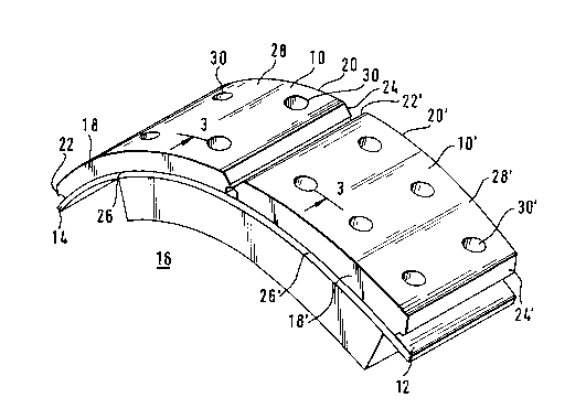
Turning to Fig. 2 of the drawings, a pair of substantially
identical friction material brake blocks (10 and 10`) are shown
mounted on the top surface (12) of a metal backing plate (14).
The combination of the brake blocks (10 and 10`) with the backing
plate (14) constitute a brake shoe (16). Inasmuch as the brake
shoe (16) depicted in Fig. 2 represents the type of shoe which
would be utilized in connection with a concentric braking system,
the brake blocks (10 and 10`) are substantially identical. For
convenience, in this description the parts and features of brake
block (10`) which are identical to those of brake block (10) will
be identified by identical prime numbers. It should be noted
that although the present invention has been shown in connection
with brake blocks (10 and 10`) of the type utilized in a
28~3346
concentric braking system the invention implies equally to the
cam and anchor shoes utilized in a cam braking system.
Again turning to Fig. 2, brake block (10) has a pair of
longitudinally extending side surfaces (18 and 20) and a pair of
laterally extending end surfaces (22 and 24). Brake block (10)
also has an arcuate bottom surface (26) which rests upon the
complementary top surface (12) of backing plate (14) and an
arcuate top surface (28) adapted to engage a similarly shaped
inner surface of a brake drum, not shown, when the brakes of a
vehicle are actuated and the brake shoe (16) moves radially
outwardly into engagement with the inner surface of the brake
drum,
When brake shoe (16) has been installed in a vehicle braking
system, the longitudinal side surfaces (18 and 20) extend in a
direction parallel to the direction of brake drum and wheel
rotation whereas the lateral end surfaces (22 and 24) extend in a
direction perpendicular to the direction of rotation of a brake
drum and wheel assembly.
The friction material brake blocks (10 and 10`) of the
present invention may be attached to the top surface (12) of a
backing plate (14) by more than one method. In the preferred
embodiment of the present invention the brake block (10) is
affixed to backing plate (14) by rivets. Turning to Fig. 3, it
may be seen that a plurality of stepped bores (30) are formed in
brake block (10). These bores are aligned with stepped bores
(32) in backing plate (14). A rivet (34) having a head (36) is
mounted in the stepped bore (32) of backing plate (14) such that
- 6 - 20~ 3~ 46
a shank (38) projects upwardly into the stepped bore (30) of
brake block (10). A punch, not shown, is driven into stepped
bore (32) to peen the end of the shank (38) as shown in Fig. 3 to
thereby affix the brake block (10) to the backing plate (14). In
addition to the mechanical fasteners utilized for affixing a
brake block to a backing plate, an adhesive fastener may be
utilized to affix the brake block (10) to the backing plate (14).
Using an adhesive to fasten a brake block to a backing plate
eliminates the need to bore holes in the brake block or the
backing plate. To fasten a brake block to a backing plate
utilizing an adhesive involves inserting the adhesive between the
arcuate bottom surface (26) of a brake block (10) and the
complementary curved top surface (12) of a backing plate (14) and
applying an appropriate combination of heat and/or pressure to
cause the adhesive to cure.
Turning again to Fig. 3, it may be observed that where a
rivet (34) has been utilized to attach the brake block (10) to
the backing plate (14), the entire thickness of the brake block
(10) is not available to be used for stopping a vehicle.
Instead, only that portion of the brake block (10) which extends
from the top surface (40) of the rivet (34) to the top surface
(28) of the brake block designated (a) is available for use in
braking a vehicle. The portion of the brake block (10) between
the top surface (40) of the rivet (34) and the arcuate bottom
surface (26) of the brake block identified as (b) in the drawing
may not be used inasmuch as the rivets (34) project into this
area and the rivets would scrape against the inner surface of a
brake drum if the brake shoe (16) were permitted to remain on a
2!~3346
7 -
vehicle after the thickness of the brake block (lo) has been
reduced below the top surface ~40) of the rivets (34).
The visual brake block wear indicator of the present
invention provides one or more reference marks on the lateral end
surfaces (22 and 24) of the brake block (10) to indicate visually
the remaining usable thickness of friction material beneath top
surface (28). One reference may be a notch or groove (42) formed
in the portion of the brake block between the bottom surface (26)
and a point (44) corresponding with the top surface (40) of rivet
(34). In other words, so long as the top surface (28) of the
brake block (lo) is not worn down to the point (44) defined on
the end surface (24) the rivets (34) which secure the brake block
(10) to the backing plate (14) will not scrape the inner surface
of a brake drum. It has been found desirable to define a minimum
safe depth point (46) on the end surface (24) by forming a
tapered surface (48) on the end surface (24). Good maintenance
practices would dictate that the brake shoe (16) should be
changed out when the top surface (28) of the brake block (10) has
worn down to the minimum safe level defined by point (46).
An operator may view the laterally extending end surface
(24) and visually determine the remaining useful thickness of
brake block material remaining on the shoe (16). So long as a
portion of the tapered surface (48) remains visible, the minimum
safe level of brake block material has not been reached. When
the tapered surface (48) no longer remains visible an operator
knows that the brake block ~10) has worn such that the minimum
safe level of material no longer remains. The brake block
- 8 - 206 33 46
~aterial between the minimum safe level set by reference point
(46) and the top of a rivet head indicated by reference level
(44) would indicate that the brake block (10) has been worn past
a minimum safe level and it must be changed to prevent the rivets
from contacting the inside surface of a brake drum.
Fig. 3 depicts a brake block (10) having a visible wear
indicator (44) - (48) adapted to be used where rivets affix the
brake block to a backing plate. As mentioned above, in some
instances the brake block (10) may be affixed to the top surface
(12) of ~ backing plate (14) by an adhesive interposed between
the bottom surface (26) of brake block (10) and the top surface
(12) of backing plate (14). This assembly constitutes a bonded
brake shoe and rivets are not needed. Because a rivet does not
project into the body of the brake block (10) to reduce the
usable thickness, the brake block of a bonded brake shoe may be
worn safely to a lesser remaining thickness (52). Turning to
Fig. 4 of the drawings, it may be seen that the visible wear
indicator on the end surface (24) of the brake block (10)
generally resembles that depicted in Fig. 3. The wear indicator
includes points 44 through 48 where the top of a mechanical
fastener is referenced at line 44, the minimum safe thickness of
brake block (10) is referenced at line (46) and a safe thickness
of brake block remains within the tapered surface (48). However,
an additional slanted surface (50) is formed on the end surface
(24). The slanted surface (50) extends between the line 44
depicting location of a mechanical fastener if one were used to
affix the brake block (10) to the backing plate (14) and a line
(52) which indicates the minimum safe thickness of brake block
9 206334~3
material when the brake block (10) has been affixed to backing
plate (14) by a bonding process. In other words, a brake block
(10) having the wear indicating means (44 through 52) depicted in
Fig. 4 may be utilized where either rivets or a bonding process
are used to affix the brake block to a backing plate.
Although the indicating means (44 through 52) depicted in
Figs. 2 through 4 preferably are molded integrally into the brake
block (10) at the same time the brake block (lo) is being
manufactured, the wear indicating means (44 through 52) also may
be formed by machining one or both end surfaces (22 and 24) of
the brake block (10).
Turning to Fig. 1 of the drawings, a wheel (54) is shown
mounted on the axle (56) of a vehicle, not shown, by a plurality
of lug nuts (58) in a well known manner. A plurality of circular
openings (60) are formed in wheel (54). These openings coincide
with openings in a brake drum, not shown, mounted behind wheel
(54). The wheel openings (60) and the openings within the brake
drum are aligned with the ends (22 and 24) of the brake blocks
(10 and 10`). Consequently, the wear indicating means (44
through 52) formed on the lateral ends of the brake blocks (10
and 10`) may be seen by looking through the wheel openings (60)
when they rotate to a position in which they are aligned with the
brake block ends (22 and 24). In a conventional drum braking
system, a pair of brake shoes (16) are mounted within the drum of
each wheel. Consequently, the friction material brake block (10
and 10`) of each of the plurality of brake shoes (16) may be seen
by looking through the wheel opening (60) when they rotate to a
2~33 16
-- 10 --
position in which the lateral ends (22 and 24) of the friction
material brake blocks (10 and 10`) become visible.
Since certain changes may be made to the above-described
apparatus, system and method without departing from the scope of
the invention herein, it is intended that all matter contained in
the description thereof or shown in the accompanying drawings
shall be interpreted as illustrative and not in a limiting sense.