Sélection de la langue

Search

Sommaire du brevet 2063501 

Énoncé de désistement de responsabilité concernant l'information provenant de tiers

Une partie des informations de ce site Web a été fournie par des sources externes. Le gouvernement du Canada n'assume aucune responsabilité concernant la précision, l'actualité ou la fiabilité des informations fournies par les sources externes. Les utilisateurs qui désirent employer cette information devraient consulter directement la source des informations. Le contenu fourni par les sources externes n'est pas assujetti aux exigences sur les langues officielles, la protection des renseignements personnels et l'accessibilité.

Disponibilité de l'Abrégé et des Revendications

L'apparition de différences dans le texte et l'image des Revendications et de l'Abrégé dépend du moment auquel le document est publié. Les textes des Revendications et de l'Abrégé sont affichés :

  • lorsque la demande peut être examinée par le public;
  • lorsque le brevet est émis (délivrance).
(12) Brevet: (11) CA 2063501
(54) Titre français: PORTE-ROULEAU DE PAPIER PEINT VERTICAL
(54) Titre anglais: VERTICAL HOLDER FOR WALL COVERING ROLLS
Statut: Périmé et au-delà du délai pour l’annulation
Données bibliographiques
(51) Classification internationale des brevets (CIB):
  • B44C 7/02 (2006.01)
  • B44C 7/06 (2006.01)
  • B65H 75/40 (2006.01)
(72) Inventeurs :
  • DEMEO, TERENCI G. (Canada)
(73) Titulaires :
  • TERENCI G. DEMEO
(71) Demandeurs :
(74) Agent: LONG AND CAMERON
(74) Co-agent:
(45) Délivré: 1994-10-18
(22) Date de dépôt: 1992-03-19
(41) Mise à la disponibilité du public: 1992-09-21
Requête d'examen: 1992-03-19
Licence disponible: S.O.
Cédé au domaine public: S.O.
(25) Langue des documents déposés: Anglais

Traité de coopération en matière de brevets (PCT): Non

(30) Données de priorité de la demande:
Numéro de la demande Pays / territoire Date
07/672,179 (Etats-Unis d'Amérique) 1991-03-20

Abrégés

Abrégé anglais


A holder for a roll of wall covering. There is a
top portion and a bottom portion which are connected by
a member. A spindle is connected to one portion and
extends towards the other portion. There is at least
one needle-like projection extending outwardly from the
front of the top portion. In use, the front of the top
portion is against a wall with the projection inserted
into the wall. The front of the bottom portion is
against a wall below the top portion. The spindle is
vertical with the roll rotatably received on the
spindle.

Revendications

Note : Les revendications sont présentées dans la langue officielle dans laquelle elles ont été soumises.


- 7 -
WHAT IS CLAIMED IS:
1. A holder for a roll of wall covering, comprising:
a top portion having a front;
a bottom portion having a front;
a member connecting the top portion and the
bottom portion;
a spindle connected to one said portion and
extending towards the other said portion; and
at least one needle-like projection extending
outwardly from the front of the top portion, whereby, in
use, the front of the top portion is against a wall with
said at least one said projection being inserted into
the wall, the front of the bottom portion being against
the wall below the top portion and the spindle being
vertical with said roll of wall covering rotatably
received thereon.
2. A holder as claimed in claim 1, wherein the fronts
of the portions project outwardly beyond the spindle to
provide clearance for the roll.
3. A holder as claimed in claim 1, wherein the bottom
portion includes a platform having a top surface for
supporting the roll, the spindle extending
perpendicularly from the platform.
4. A holder as claimed in claim 1, wherein said at
least one projection is angled downwardly from the
horizontal when the holder is positioned for use.

- 8 -
5. A holder as claimed in claim 1, wherein there are
two said projections which are horizontally spaced-apart
from each other when the holder is postioned for use.
6. A holder as claimed in claim 1, wherein the spindle
is of a flexible material.
7. A holder as claimed in claim 1, wherein the
holder, apart from the projections, is one piece of a
resilient material.
8. A holder as claimed in claim 1, wherein the top
portion and the member are elongated, the top portion
being perpendicular to the member and having a top
surface which is flat and horizontal when the holder is
positioned for use.

Description

Note : Les descriptions sont présentées dans la langue officielle dans laquelle elles ont été soumises.

2063501
V~RTICAL HOLDKR FOR WALL COVEXING R~LLS
BACKGROUND OF THE INVENTION
1. Field of the Invention
This invention relates to a device for holding
rolls of wall covering vertically while a strip of the
wall covering is being applied to a wall.
2. Description of the Prior Art
Wall paper borders and other wall coverings
conventionally come in cylindrical rolls. It is often
an awkward task, sometimes requiring two persons, to
unroll the wall covering from the roll and apply it to a
wall. For example, one person may have to hold the roll
and gradually move it from one corner of the wall
towards another corner as the strip of wall covering is
applied to the wall.
1 5
Attempts have been made to provide a device for
holding a roll of wall covering and allowing a single
person to apply it. For example, in United States
Patent No. 4,263,347 to Banta, a special pair of stilts
have been provided, one of which has a holder for
rotatably receiving a roll of masking material. The
apparatus however would be relatively expensive and not
everyone wants to wear stilts while applying wall
coverings.
Vertical holders for rolled paper or similar
materials are disclosed in United Sta.es Patent No.
4,824,038 to Chandler and 4,848,690 to Lemoine.
However, these devices are not suitable for holding
rolls of wall paper, because they contemplate permanent
fixation to a wall. #
/

20635~1
..~
SUMMARY OF THE INVENTION
It is an object of the invention to provide a device
which is capable of temporarily holding a roll of wall
covering in a position on a wall, particularly one
constructed of dry wall.
It is a further object of the invention to provide an
improved holder for wall coverings which can be moved to
different positions along a wall as a strip of wall
covering is applied to the wall.
In accordance with these objects, the invention provides
a holder for a roll of wall covering which includes a
top portion having a front and a bottom portion having a
front. A member connects the top portion and the bottom
portion. A spindle is connected to one of the portions
and extends toward the other portion. There is at least
one needle-like projection extending outwardly from the
front of the top portion. In use, the front of the top
portion is against a wall with the projection inserted
into the wall. The front of the bottom portion is
against the wall below the top portion. The spindle is
vertical with the roll of wall covering rotatably
received thereon.
The invention is advantageous over the prior art in
providing a simple, inexpensive device capable of
holding a roll of wall covering, while a strip of the
wall covering is being applied to the wall. The device
can save considerable labor and cost when used to
replace a second worker.

2063501
~~
BRIEF DESCRIPTION OF THE DRAWINGS
In the drawings:
Fig. 1 is a top, front isometric view of a holder
for a roll of wall covering, according to an embodiment
of the invention;
Fig. 2 is a fragmentary side elevation of the front
of the top portion thereof and a needle-like projection
extending therefrom; and
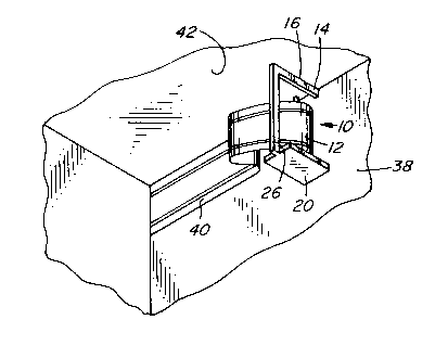
Fig. 3 is an isometric view showing a fragment of a
wall and a holder as shown in ~ig. 1 holding a roll of
wall covering, while a strip of the wall covering is
being applied to the wall.
DESCRIPTION OF THE PREFERRED EMBODIMEN~S
Fig. 1 shows a holder 10 for a roll 12 of wall
covering, shown only in Fig. 3. The holder has a top
portion 14 which in this embodiment is an elongated
member with a flat top 16 and front 18. Other
configurations and shapes of top portions could be used
instead.
The holder 10 also has a bottom portion 20 which
includes a platform 22 having a top surface 24 for
supporting roll 12 shown in Fig. 3. In this particular
embodiment, the platform is rectangular, but other
shapes, for example circular, and other configurations
of bottom portions could be substituted.
An elongated member 26 rearwardly connects the top
portion and bottom portion of the holder. In this

20635Ql
embodiment the member is straight and similar in shape
to the top portion, meeting it at right angles.
However, other shapes and configurations could also be
used in alternative embodiments.
A spindle 28 is connected to the bottom portion
20. In this example it is located centrally on platform
22 and extends upwardly, having a top 30 just below top
portion 14. In this preferred example, the top portion
14, member 26, bottom portion 20 and spindle 28 are
formed of a single piece of relatively rigid, but
resilient plastic material, such as nylon. This allows
the spindle 28 to be bent to one side to place roll 12
over the spindle. The spindle then returns to the
initial position shown in Fig. 1. However, the device
could be made of several pieces and the spindle could be
removable to insert the roll or the top portion could be
movable to allow the roll to be placed over the
spindle. Alternatively, the spindle could be connected
to the top portion and extend towards the bottom
portion. Many other configurations are also possi~le.
The bottom portion 20 has a front 32 which projects
outwardly from the position of the spindle on the
platform. Likewise, the front 18 of top portion 14
projects outwardly from the top of the spindle. ffl is
gives clearance for the thickness of the roll of wall
covering 12 and allows it to rotate when the fronts of
the top and bottom portions contact a wall.
There are two needle-like projections 34 and 36
connected to top portion 14 at the front 18 thereof.
The projections have rear portions tightly received in
apertures formed in the front of the top portion. As

20635`01
may be seen for projection 34 in Fig. 2, the projections
are angled downwardly from the horizontal when the
holder is positioned for use as shown. In the
illustrated embodiment, the projections are angled about
10- downwardly, though the angle is not critical. In
alternative embodiments, there could be a single
projection, though two are preferred as shown.
Acditional projections could also be used, but are not
necessary.
The holder 10 is primarily intended for use on a
wall 38 made of dry wall as shown in Fig. 3. miS is
perhaps the most common material used at present to make
walls and consists of a gypsum compound between layers
of paper. Projections 34 and 36 are easily inserted
into dry wall and cause no serious damage, leaving only
small holes which are covered by the wall covering. The
holder could also be used on some other types of walls
made of softer materials, such as various fiber boards
and soft wall panelling, but primarily it is intended
for dry wall.
In use, the device is positioned between the
corners of the wall. Fig. 3 shows it being used for
appling a strip 40 of border material along the top of
wall 38. The flat top 16 of the top portion is
positioned against the ceiling 42. The strip 40 can
then be unrolled and applied to the wall using the
adhesive already applied to prepasted borders and
pre-moistened by the user, or a separate adhesive for
non-prepasted borders.
Once strip 40 has been secured as shown in the
drawing, the user simply grasps the holder 10 and pulls
it away from the wall, thus removing the projections
from the wall. It can then be positioned further to the

206~501
right, from the point of view of Fig. 3, and an
additional strip of the wall covering can be applied to
the wall. Of course it is also possible to start at the
right corner and move to the left.
During use, it will be noted that the projections
34 and 36 are inserted into the wall until front 18 of
the top portion contacts the wall. Front 32 of bottom
p~rtion 20 also contacts the wall.
It will be realized by someone skilled in the art
that many of the details provided above are by way of
example only and that many variations and alternatives
are possible within the scope of the invention which is
to be interpreted with reference to the following
claims.

Dessin représentatif
Une figure unique qui représente un dessin illustrant l'invention.
États administratifs

2024-08-01 : Dans le cadre de la transition vers les Brevets de nouvelle génération (BNG), la base de données sur les brevets canadiens (BDBC) contient désormais un Historique d'événement plus détaillé, qui reproduit le Journal des événements de notre nouvelle solution interne.

Veuillez noter que les événements débutant par « Inactive : » se réfèrent à des événements qui ne sont plus utilisés dans notre nouvelle solution interne.

Pour une meilleure compréhension de l'état de la demande ou brevet qui figure sur cette page, la rubrique Mise en garde , et les descriptions de Brevet , Historique d'événement , Taxes périodiques et Historique des paiements devraient être consultées.

Historique d'événement

Description Date
Exigences relatives à la révocation de la nomination d'un agent - jugée conforme 2020-09-02
Exigences relatives à la nomination d'un agent - jugée conforme 2020-09-02
Exigences relatives à la révocation de la nomination d'un agent - jugée conforme 2020-09-01
Exigences relatives à la nomination d'un agent - jugée conforme 2020-09-01
Inactive : CIB de MCD 2006-03-11
Inactive : Demande ad hoc documentée 1997-03-19
Le délai pour l'annulation est expiré 1996-09-19
Lettre envoyée 1996-03-19
Accordé par délivrance 1994-10-18
Demande publiée (accessible au public) 1992-09-21
Toutes les exigences pour l'examen - jugée conforme 1992-03-19
Exigences pour une requête d'examen - jugée conforme 1992-03-19

Historique d'abandonnement

Il n'y a pas d'historique d'abandonnement

Titulaires au dossier

Les titulaires actuels et antérieures au dossier sont affichés en ordre alphabétique.

Titulaires actuels au dossier
TERENCI G. DEMEO
Titulaires antérieures au dossier
S.O.
Les propriétaires antérieurs qui ne figurent pas dans la liste des « Propriétaires au dossier » apparaîtront dans d'autres documents au dossier.
Documents

Pour visionner les fichiers sélectionnés, entrer le code reCAPTCHA :


Pour visualiser une image, cliquer sur un lien dans la colonne description du document. Pour télécharger l'image (les images), cliquer l'une ou plusieurs cases à cocher dans la première colonne et ensuite cliquer sur le bouton "Télécharger sélection en format PDF (archive Zip)" ou le bouton "Télécharger sélection (en un fichier PDF fusionné)".

Liste des documents de brevet publiés et non publiés sur la BDBC .

Si vous avez des difficultés à accéder au contenu, veuillez communiquer avec le Centre de services à la clientèle au 1-866-997-1936, ou envoyer un courriel au Centre de service à la clientèle de l'OPIC.


Description du
Document 
Date
(aaaa-mm-jj) 
Nombre de pages   Taille de l'image (Ko) 
Abrégé 1993-12-11 1 14
Page couverture 1993-12-11 1 13
Revendications 1993-12-11 2 44
Dessins 1993-12-11 1 20
Description 1993-12-11 6 184
Page couverture 1996-02-12 1 16
Abrégé 1994-10-18 1 15
Revendications 1994-10-18 2 45
Dessins 1994-10-18 1 21
Description 1994-10-18 6 197
Dessin représentatif 1999-07-02 1 10
Taxes 1994-03-08 1 33
Taxes 1995-03-17 1 39
Courtoisie - Lettre du bureau 1992-09-03 1 43
Correspondance de la poursuite 1994-04-28 1 25
Courtoisie - Lettre du bureau 1994-06-06 1 54
Correspondance reliée au PCT 1994-08-04 1 27
Correspondance reliée au PCT 1994-07-29 1 29
Courtoisie - Lettre du bureau 1994-09-12 2 42