Sélection de la langue

Search

Sommaire du brevet 2063967 

Énoncé de désistement de responsabilité concernant l'information provenant de tiers

Une partie des informations de ce site Web a été fournie par des sources externes. Le gouvernement du Canada n'assume aucune responsabilité concernant la précision, l'actualité ou la fiabilité des informations fournies par les sources externes. Les utilisateurs qui désirent employer cette information devraient consulter directement la source des informations. Le contenu fourni par les sources externes n'est pas assujetti aux exigences sur les langues officielles, la protection des renseignements personnels et l'accessibilité.

Disponibilité de l'Abrégé et des Revendications

L'apparition de différences dans le texte et l'image des Revendications et de l'Abrégé dépend du moment auquel le document est publié. Les textes des Revendications et de l'Abrégé sont affichés :

  • lorsque la demande peut être examinée par le public;
  • lorsque le brevet est émis (délivrance).
(12) Brevet: (11) CA 2063967
(54) Titre français: METHODE ET APPAREIL DE TREMPAGE A CHAUD DE BANDES D'ACIER
(54) Titre anglais: METHOD AND APPARATUS FOR HOT-DIPPING STEEL STRIP
Statut: Périmé et au-delà du délai pour l’annulation
Données bibliographiques
(51) Classification internationale des brevets (CIB):
  • C23C 02/12 (2006.01)
  • C23C 02/02 (2006.01)
  • C23F 04/00 (2006.01)
  • C23G 05/00 (2006.01)
(72) Inventeurs :
  • FUKUI, YASUSHI (Japon)
  • MIONO, TADAAKI (Japon)
  • NAKAMOTO, KAZUNARI (Japon)
  • YOSHII, TSUGUYASU (Japon)
(73) Titulaires :
  • NISSHIN STEEL CO., LTD.
(71) Demandeurs :
  • NISSHIN STEEL CO., LTD. (Japon)
(74) Agent: SMART & BIGGAR LP
(74) Co-agent:
(45) Délivré: 1999-03-30
(22) Date de dépôt: 1992-03-25
(41) Mise à la disponibilité du public: 1992-09-27
Requête d'examen: 1994-08-23
Licence disponible: S.O.
Cédé au domaine public: S.O.
(25) Langue des documents déposés: Anglais

Traité de coopération en matière de brevets (PCT): Non

(30) Données de priorité de la demande:
Numéro de la demande Pays / territoire Date
3-86169 (Japon) 1991-03-26

Abrégés

Abrégé français

Nettoyage d'une bande d'acier par pulvérisation-attaque à l'aide de faisceaux ioniques d'argon. Grâce à cette pulvérisation-attaque, on supprime une pellicule d'oxydes d'éléments facilement oxydables, comme le chrome et le silicium. La bande d'acier nettoyée est trempée à chaud.


Abrégé anglais


A steel strip is cleaned by sputtering-etching
with ion beams of argon. By the sputtering-etching, an
oxide film of easily oxidable elements such as chromium
and silicon is removed. The cleaned steel strip is
hot-dipped.

Revendications

Note : Les revendications sont présentées dans la langue officielle dans laquelle elles ont été soumises.


CLAIMS:
1. A method for hot-dipping a steel strip using an
apparatus that incorporates a hot dipping bath, a vacuum
chamber provided upstream of the hot dipping bath and
positioned so as to have an outlet of the vacuum chamber
feed directly into the hot dipping bath, ion beam ejecting
means provided in the vacuum chamber upstream of the hot
dipping bath, for activating a surface of the steel strip
using ion beam sputtering-etching, the ion beam ejecting
means being further for heating the steel strip prior to
entering the hot dipping bath, and conveying means for
conveying the steel strip to be treated through the vacuum
chamber and directly into the hot dipping bath, said
method comprising the steps of:
conveying the steel strip to be treated through the
vacuum chamber and the hot dipping bath;
cleaning a surface of the steel strip by sputtering-etching
with the ion beam ejecting means; and
hot-dipping plating the steel strip through the hot
dipping bath directly from the vacuum chamber.
2. A method according to claim 1, further comprising the
step of: heating the steel strip when the temperature of
the steel strip is lower than a temperature for the
hot-dipping plating.
3. A method according to claim 1 wherein the sputtering-etching
is performed by irradiating ion beams of argon.
4. An apparatus for hot-dipping a steel strip,
comprising:
a hot dipping bath;
a vacuum chamber provided upstream of the hot dipping
bath and positioned so as to have an outlet of said vacuum
chamber feed directly into said hot dipping bath;
ion beam ejecting means provided in the vacuum
chamber upstream of said hot dipping bath, for activating

11
a surface of the steel strip using ion beam sputtering-etching,
said ion beam ejecting means being further for
heating the steel strip prior to entering said hot dipping
bath; and
conveying means for conveying the steel strip to be
treated through said vacuum chamber and said hot dipping
bath.
5. An apparatus according to claim 4, wherein said ion
beam ejecting means includes ion beam ejecting devices
provided on opposite sides of a path line of the steel
strip.
6. An apparatus according to claim 4, further
comprising:
heating means provided between said ion beam ejecting
means and the outlet of said vacuum chamber, for heating
the steel strip at least to a predetermined temperature
for hot-dipping plating.
7. An apparatus according to claim 4, wherein said ion
beam ejecting means includes means for ejecting argon
ions.
8. An apparatus for hot-dipping a steel strip,
comprising:
a hot dipping bath;
a vacuum chamber provided upstream of the hot dipping
bath and positioned so as to have an outlet of said vacuum
chamber feed into said hot dipping bath;
ion beam ejecting means provided in the vacuum
chamber upstream of said hot dipping bath, for activating
a surface of the steel strip using ion beam
sputtering-etching;
temperature determining means for determining if a
temperature of the steel strip is within a predetermined
temperature for hot-dipping plating;
heating means provided between said ion beam ejecting

12
means and the outlet of said vacuum chamber, for heating
the steel strip at least to the predetermined temperature
for hot-dipping plating; and
conveying means for conveying the steel strip to be
treated through said vacuum chamber and said hot dipping
bath.
9. An apparatus according to claim 8, wherein said ion
beam ejecting means includes ion beam ejecting devices
provided on opposite sides of a path line of the steel
strip.
10. An apparatus according to claim 8, wherein said ion
beam ejecting means includes means for ejecting argon
ions.
11. An apparatus according to claim 8, wherein said
vacuum chamber provided upstream of the hot dipping bath
is further positioned so as to have the outlet thereof
directly connected into said hot dipping bath.

Description

Note : Les descriptions sont présentées dans la langue officielle dans laquelle elles ont été soumises.

2063967
TITLE OF THE INVENTION
Method and Apparatus for Hot-Dipping Steel Strip
BACXGROUND OF THE lNV ~:N~l~lON
The present invention relates to a method and an
apparatus for continuously hot-dipping steel strip,
wherein a pretreatment of the steel is improved for
plating.
A hot dipping apparatus of steel strip is provided
with a pretreating device for removing an oxide film on
the steel strip before plating, thereby improving
wettability of the steel and preventing the formation
of bare spots on the steel strip. In the pretreating
device, the steel strip is heated to anneal and 1l ~v~
combustible impurities at the same time. Thereafter,
the steel strip is reduced by reducing gas.
However, in the case that the steel contains
easily oxidizable elements such as chromium, silicon
and aluminum, which steel is for example stainless
steel, the oxide film can not be removed by the
reducing gas. Consequently, the pretreated steel strip
has low wettability.
The hot dipping is performed by intermetallic
reaction, and the reaction is influenced by the easily
oxidizable elements. Therefore, defects such as bare
spots are liable to occur on the steel containing
easily oxidizable elements.

2 2063967
Such a steel strip containing easily oxidizable
elements can be plated by vacuum deposition, if the
strip is heated.
If the steel strip containing easily oxidizable
elements of the steel strip is electroplated before the
hot dipping, the wettability of the strip is improved,
thereby providing a product without defects. However,
such a method renders the manufacturing process
c~ cated~ thereby increasing the manufacturing cost.
SUMMARY OF THE lNv~L.llON
An object of the pxesent invention is to provide a
hot dipping method and apparatus in which the surface
of a steel strip is activated by sputtering-etching,
thereby developing the wettability of the steel strip
and preventing the formation of the bare spot in the
plating surface.
According to the present invention, there is
provided a hot dipping method of a steel strip
comprising steps of cleaning the surface of the steel
strip by sputtering-etching with ion beams and
hot-dipping the steel strip. At sputtering-etching, if
the temperature of the steel strip is lower than the
temperature for the hot-dipping plating, the steel is
heated at the same time.
A hot dipping apparatus comprises a vacuum chamber
provided on the upstream of a hot dipping bath. The

3 2063967
vacuum chamber has an ion beam ejecting device provided
on opposite sides of a path line of the steel strip.
Any elements or molecules can be used for the ion
beam for sputtering-etching. However, it is
advantageous to use an ion beam of argon in
consideration of easy h~n~ 1 i ng, low cost, corrosion
resistance after plating, and high speed treatment. In
the sputtering-etching, ion beams impact the surface of
the steel strip to splash atoms thereon by sputtering
effect and etch the surface.~ Consequently, the oxide
film of easily oxidizable elements is removed from the
surface of the steel strip.
Even if argon gas leaks from the ejecting device
into the vacuum chamber, the surface of the steel is
maintained in a clean condition until the steel strip
is dipped in the hot dipping bath.
A part of kinetic energy of the ion beam impacted
to the steel strip changes to heat energy. As a
result, the temperature of the steel strip properly
increases for the hot dipping. If the temperature of
the steel is insufficient, the steel strip is heated by
heaters in the vacuum chamber.
The other objects and features of this invention
will become understood from the following description
with reference to the accompanying drawings.
BRIEF DESCRIPTION OF DRAWINGS

4 2063967
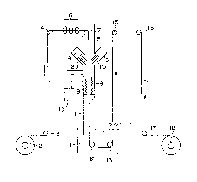
A single figure is a schematic illustration
showing a hot dipping apparatus according to the
present invention.
DETAILED DESCRIPTION OF ~HE PREFERRED EMBODIMENT
Referring to the drawing, a steel strip 1 is fed
from a pay off reel 2 to a vacuum chamber 5 through
deflector rollers 3 and 4. A sealing device 6 of a
roller type is provided in the vacuum chamber 5
adjacent to an inlet thereof. The vacuum chamber 5 is
10 .
further provided with a deflector roller 7 for
downwardly guiding the steel strip 1, ion beam ejecting
devices 8, and heaters 9 both of which are provided on
opposite sides of the path of the steel strip. A
vacuum pump 10 is communicated with the vacuum chamber
5 to maintain the pressure in the chamber 5 to a
predet~rr;ne~ reducing atmosphere. An outlet of the
chamber 5 is immersed in a hot dipping bath 11. The
bath 11 also serves as a sealing device for the outlet
of the ~h~ bcr 5. The steel strip 1 is heated by the
heaters 9 to the same temperature as the bath 11.
In the bath 11, immersion rollers 12 and 13 are
disposed to guide the strip in the bath. The steel
strip 1 is guided in the upper direction b~ the roller
13. The plating thickness is adjusted by a gas wiping
device 14. The steel strip 1 is fed to a reel 18

s 2063967
through deflector rollers 15, 16 and 17 and wound
thereon.
In order to perform sputtering-etching, the air in
the chamber 5 is discharged to provide a low pressure
of about lX10-3Pa with the vacuum pump 10. Argon ion
beams 19 and 20 are ejected from the ejecting devices 8
to the steel strip 1 for performing the
sputtering-etching. During the operation, the
temperature of the steel strip 1 is increased by the
ion beams. If the temperature is insufficient to the
plating, the heaters 9 are operated to heat the steel
strip 1.
EXAMPLE
A degreased steel strip of SUS 430 stainless steel
(finished material at 2B, having width of 100 mm and
thickness of 0.5 mm) was plated with Aluminum alloy by
hot dipping under the conditions shown in table 1. The
temperature of the steel strip 1 was controlled to
650~C by the heaters 9 before immersing in the bath.

6 20639~7
TABLE 1: Conditlons of Sputtering-Etching
and Hot Dipping
ion A r~
energy 1 0 k e V
- ~ current density2 m A f c mZ
o
-~ irradiation angle40 degrees
irradiation length 3 0 c m
c~n~C;ticn S i 9.2 weight%
residual: inevitable
~ impurities
~ and Al F e 1.6 ~eight%
; temperature 6 5 0
~ .
thickness 2 0 ~ m ~one side)
~0

7 2063967
The plating layer formed on the steel strip was
~x~ined to investigate bare spot ratio and adhesion
thereof. The result is shown in table 2. The pare
spot ratio represents bare spot area per 0.05 m2. The
plating adhesion was investigated by two kinds bending
tests. In the first test, the steel strip was bent at
180 degrees until the opposite bent portions engage
with each other (Ot bending). In the second test, the
steel strip was bent at 180 degrees by interposing
another steel strip having the same thickness
there-between (lt bending). Thereafter, a piece of a
cellophane tape was stuck on the bent portion. Then,
the tape is 1~- -,ved therefrom and the peeling off of
the plating layer was e~ ined. In the table, a mark
represents no peeling at Ot bending. A mark O
represents the fact that a part of the plating layer is
peeled off at Ot bending and not peeled at lt bending.
A mark ~ represents that a part of the plating layer is
peeled off at lt bending, and a mark x represents that
the entire plating layer is peeled off at lt bending.

8 2063967
TABLE 2: Relationship Between Line Speed and
Plating Condition
line spe~l (m/min) bare spot ratio (~) adhesion
0
2 0 0 1~
~ .~ 3 0 o ~,
~j 4 0 0
,~ 5 0 0
8 5 5
~i O O
(ll
4 0 8 O
3~ 50 1 5 ~
-) ~
o 5 5 3 9
6 0 ~ 3 x

9 2063967
From the table 2, it will be seen that if the
steel strip is pretreated by sputtering-etching with
ion beams, the steel strip is plated with a good
adhesion without bare spot at a high operating speed.
To the contrary, the comparative examples have bare
spots. The bare spot ratio increases with the
operating s~eed.
In accordance with the present invention, the
surface of the steel strip to be hot-dipped is cleaned
by sputtering-etching with the ion beam. Since the
atoms on the surface of the steel strip is 1~ -,ved by
collision of the ion beam, the steel including easily
oxidizable elements is sufficiently activated. As a
result, it is possible to hot-dip the steel strip with
improving the adhesion without bare spot. The
pretreating apparatus of the present invention can
reduce the length of the line of the pretreatment so
that starting or stopping of the apparatus can be
easily perforMed.
While the presently preferred embodiment of the
present invention has been shown and described, it is
to be understood that this disclosure is for the
purpose of illustration and that various changes and
modifications may be made without departing from the
scope of the invention as set forth in the appended
claims.

Dessin représentatif
Une figure unique qui représente un dessin illustrant l'invention.
États administratifs

2024-08-01 : Dans le cadre de la transition vers les Brevets de nouvelle génération (BNG), la base de données sur les brevets canadiens (BDBC) contient désormais un Historique d'événement plus détaillé, qui reproduit le Journal des événements de notre nouvelle solution interne.

Veuillez noter que les événements débutant par « Inactive : » se réfèrent à des événements qui ne sont plus utilisés dans notre nouvelle solution interne.

Pour une meilleure compréhension de l'état de la demande ou brevet qui figure sur cette page, la rubrique Mise en garde , et les descriptions de Brevet , Historique d'événement , Taxes périodiques et Historique des paiements devraient être consultées.

Historique d'événement

Description Date
Inactive : CIB de MCD 2006-03-11
Le délai pour l'annulation est expiré 2002-03-25
Lettre envoyée 2001-03-26
Accordé par délivrance 1999-03-30
Inactive : Taxe finale reçue 1998-12-15
Préoctroi 1998-12-15
Un avis d'acceptation est envoyé 1998-10-27
Lettre envoyée 1998-10-27
Un avis d'acceptation est envoyé 1998-10-27
Inactive : Dem. traitée sur TS dès date d'ent. journal 1998-10-22
Inactive : CIB attribuée 1998-09-17
Inactive : CIB enlevée 1998-09-17
Inactive : CIB attribuée 1998-09-17
Inactive : Approuvée aux fins d'acceptation (AFA) 1998-09-10
Lettre envoyée 1998-07-08
Inactive : Renseign. sur l'état - Complets dès date d'ent. journ. 1998-05-20
Exigences de rétablissement - réputé conforme pour tous les motifs d'abandon 1998-05-01
Inactive : Abandon. - Aucune rép dem par.30(2) Règles 1998-03-04
Inactive : Dem. de l'examinateur par.30(2) Règles 1997-11-04
Toutes les exigences pour l'examen - jugée conforme 1994-08-23
Exigences pour une requête d'examen - jugée conforme 1994-08-23
Demande publiée (accessible au public) 1992-09-27

Historique d'abandonnement

Il n'y a pas d'historique d'abandonnement

Taxes périodiques

Le dernier paiement a été reçu le 1999-02-22

Avis : Si le paiement en totalité n'a pas été reçu au plus tard à la date indiquée, une taxe supplémentaire peut être imposée, soit une des taxes suivantes :

  • taxe de rétablissement ;
  • taxe pour paiement en souffrance ; ou
  • taxe additionnelle pour le renversement d'une péremption réputée.

Les taxes sur les brevets sont ajustées au 1er janvier de chaque année. Les montants ci-dessus sont les montants actuels s'ils sont reçus au plus tard le 31 décembre de l'année en cours.
Veuillez vous référer à la page web des taxes sur les brevets de l'OPIC pour voir tous les montants actuels des taxes.

Historique des taxes

Type de taxes Anniversaire Échéance Date payée
TM (demande, 6e anniv.) - générale 06 1998-03-25 1997-12-23
Rétablissement 1998-05-01
Taxe finale - générale 1998-12-15
TM (demande, 7e anniv.) - générale 07 1999-03-25 1999-02-22
TM (brevet, 8e anniv.) - générale 2000-03-27 2000-02-17
Titulaires au dossier

Les titulaires actuels et antérieures au dossier sont affichés en ordre alphabétique.

Titulaires actuels au dossier
NISSHIN STEEL CO., LTD.
Titulaires antérieures au dossier
KAZUNARI NAKAMOTO
TADAAKI MIONO
TSUGUYASU YOSHII
YASUSHI FUKUI
Les propriétaires antérieurs qui ne figurent pas dans la liste des « Propriétaires au dossier » apparaîtront dans d'autres documents au dossier.
Documents

Pour visionner les fichiers sélectionnés, entrer le code reCAPTCHA :


Pour visualiser une image, cliquer sur un lien dans la colonne description du document. Pour télécharger l'image (les images), cliquer l'une ou plusieurs cases à cocher dans la première colonne et ensuite cliquer sur le bouton "Télécharger sélection en format PDF (archive Zip)" ou le bouton "Télécharger sélection (en un fichier PDF fusionné)".

Liste des documents de brevet publiés et non publiés sur la BDBC .

Si vous avez des difficultés à accéder au contenu, veuillez communiquer avec le Centre de services à la clientèle au 1-866-997-1936, ou envoyer un courriel au Centre de service à la clientèle de l'OPIC.


Description du
Document 
Date
(aaaa-mm-jj) 
Nombre de pages   Taille de l'image (Ko) 
Description 1994-03-04 9 213
Revendications 1994-03-04 1 21
Dessins 1994-03-04 1 10
Abrégé 1994-03-04 1 8
Revendications 1998-08-18 3 104
Dessin représentatif 1999-06-28 1 8
Courtoisie - Lettre d'abandon (R30(2)) 1998-05-20 1 171
Avis de retablissement 1998-07-07 1 177
Avis du commissaire - Demande jugée acceptable 1998-10-26 1 163
Avis concernant la taxe de maintien 2001-04-22 1 178
Taxes 1999-02-21 1 32
Correspondance 1998-12-14 1 35
Taxes 1997-12-22 1 31
Taxes 1996-12-10 1 31
Taxes 1995-11-28 1 30
Taxes 1994-12-06 1 34
Taxes 1994-01-18 1 28
Courtoisie - Lettre du bureau 1994-09-14 1 55
Correspondance de la poursuite 1994-08-23 2 52
Correspondance de la poursuite 1994-11-22 4 124
Correspondance de la poursuite 1998-04-30 2 60
Demande de l'examinateur 1997-11-03 2 82