Note : Les descriptions sont présentées dans la langue officielle dans laquelle elles ont été soumises.
- 2~64330
920083-shf
GR 91PS516 US
"HIGHLY THERMALLY LOADED E~ECTRIC LAMP, AND
METHOD OF ITS MANUFACTURE, WITH REDUCED
UV LIGHT EMISSION"
* * * * * *
The preseQt invcntion relates to suppression of
transmls~ion of ultravlolet (UV) llght through a glsss layer,
snt more partlcularly to a glaze or coaelng on a quartz glass
bulb of an electrlc lamp, whlch, ln operatlon, becomes very
hot.
High-pressure dlscharge lamps as well as highly loaded
halogen lncande~cent lamps generatc a relatlvely hlgh
proportion of UY radlatlon when the lamps operate. The lamp
bulb~ are mate of quartz glass due the hlgh thermal loadlng
placed on th- bulb. Quartz glass has a hlgh degree of
transparency for UV radiatlon in the range of between 400 nm
to 200 nm. For many appllcatlon3, the energy-rlch UV
radlation is undesirable, ant may be harmful. UV radlation, in
20~33~
excess, has undesirable biological effects and, additionally,
causes plastics and plastic components to become brittle.
It is therefore necessary to reduce the transparency of the
lamp bulb to UV radiation unless the lamps have an outer
covering envelope which absorbs UV-radiation.
The referenced U.S. Patent 3,531,677, Loughridge,
describes a high-pressure discharge lamp having a discharge
vessel made of quartz glass. It is furnished with a UV
absorbing coating or glaze. The UV abYorbing coating is made
of a eutectlc mixture of aluminum silicate, AL203.SiO2.
The eutectic coating 18 doped wlth between
0.05% to 10~ of UV absorbing sub$tances, for example
T102 or CeO2.
The coating is made by providing a suspension of
the A1203. SiO2 mixture and the UV absorbing substance,
that is, either TiO2 or CeO2, in isopropyl alcohol with water.
This suspension is sprayed on the bulb, driet, and then fired
ln. A glaze wlll result. It has been found that the UV
transparency of such lamps i9 not reduced to a currently
desired extent by the UV absorbing coating. The manufacturing
process to 80 coat the~e bulbs, particularly drying and
firing of the coating, i8 comparatlvely time-consuming and
thus expensive for mass-produced lamp bulbs.
It has also been proposed to dope quartz glass
dlrectly when the gla~s is used for lamp bulbs, by doping the
quartz glass with UV absorbing ions. Thl~ re3ult3 in a
reduction of the vlscosity of the quartz gla 8, 80 that the
thermal loading which can be placed on a quartz glass ls
reduced; this reduction also reduces the light output available
3~ from the lamp.
2~6~330
27813-11
It is an object to reduce the UV transparency of glass,
and specifically quartz glass bulbs used in connection with
electric lamps, to a high degree, without, however, reducing the
transparency of the glass in the visible spectral region.
Briefly, a UV absorbing coating which comprises a glaze
including cerium fluoride (CeF3) and aluminum silicate
(A12O3.SiO2) is applied to the glass.
According to one aspect of the present invention there
is provided an electric lamp having a bulb of quartz glass; light
emitting means within said bulb, said light emitting means, in
operation, generating heat; and an, ultraviolet (UV) absorbing
coating on the quartz ~làss, wherein, in accordance with the
invention, the UV absorbing coating comprises a glaze which in-
cludes cerium fluoride (CeF3) and aluminum silicate (A12O3.SiO2).
According to a further aspect of the present invention
there is provided a method ,to make an electric lamp as defined
above, said method comprising the followin~ steps: (providing a
lamp bulb; providing a suspension which comprises CeF3 and
A12O3.SiO2 in a thinner, in which the ratio, by weight, of CeF3
to A12O3.SiO2 is between about 1 : 1 and 3 : 1; milling the
suspension to obtain a grain size of the solid substances in the
suspension which is less than 300 mesh; thinning the suspension
with an additional thinner; applying the suspension to a surface
of the glass bulb; drying the coating; heating the glass bulb to
about 400C; and firing the coating to form a glaze.
The degree of transmission of the lamp bulb in accordance
206~33~
27813-11
with the present invention with respect to UV radiation is
substantially decreased already in layer thicknesses of only a
few micrometers. It has been found that coatings with cerium
fluoride (CeF3), under otherwise equal conditions, have a higher
UV absorbing effect than coatings with CeO2. CeF3 has a specific
advantage with respect to the UV absorbing material titanium
dioxide, TiO2, in that CeF3 also absorbs long-wave UV radiation;
TiO2 absorbs primarily short-wave UV radiation.
The coating of CeF3 in accordance with the present
invention does not decrease the transparency of the glass, that
- is, the lamp bulb, if the coatings are not too thick with respect
to visible light. The process of manufacture can be carried out
in much shorter time than in accordance with the prior art.
The lamps have another unexpected advantage in that the tendency
of auartz molecules to vaporize from the lamp bulb when placed in
a moist or damp atmosphere, which results in roughening of the
surface of the lamp bulb, is reduced by the coating.
In accordance with a feature of the invention, a
suspension of CeF3 and A12O3.SiO2 is formed in a suitable solvent,
e.g. an alcohol.
The suspension is then ground, so that the grain size
is small, the suspension is thinned in a thinner, and then applied
to the surface of the ~uartz glass bulb. The bulb is then dried,
the bulb is heated to about 400~C, and then fired to form the
glaze. Preferably, the proportion of CeF3 to A12O3.SiO2 is
between about 1 : 0 and 3 : 1, ~specially about 2 : 1.
2064330
27813-11
All proportions given in the specification and claims,
unless otherwise noted, are by weight.
The invention will be further described with reference
to the accompanying drawings in which:
Figure 1 illustrates, schematically, a high-pressure
discharge lamp having a coating in accordance with the present
invention;
Figure la is a schematic view of a double-ended halogen
incandescent lamp, having the coating of the present invention;
and
Figure 2 is a graph of light transmissivity, both within
the UV and visible range, of the lamp bulb of Figures 1 and la
(ordinate) with respect to wave length (abscissa), wherein curve
2 shows the transmissivity with the coating and curve 1 the
transmissivity without the coating, in accordance with the prior
art~
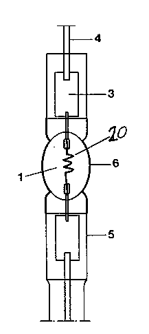
Referring first to Figures 1 and la:
Figure 1 illustrates a metal-halide high-pressure dis-
charge lamp, for example suitable for incorporation in an auto-
motive vehicle headlight. The lamp has a discharge vessel 1 of
quartz glass, in which two electrodes 2, 2' are located. The
electrodes, each, are connected via a molybdenum foil 3, pinch-
sealed in a pinch seal 5 to external electrical connecting leads
4. The discharge vessel 1 is held in position in a plastic base
- not shown - fitted to the pinch seals 5. m e plastic base might,
absent the present
- 4a -
2G6~33~
invention, be rendered brittle and, in due course, would fail
due to the exposure to UV radiation, transmitted through the
quartz glass vessel 1. This UV radiation is of high energy.
Failure of the lamp base, of course, would lead to complete
failure of the overall lamp - base unit or combination.
Fig. la shows a lamp, which in all respect-~ can be
similar to the lamp of F~g. 1, except that the discharge
electrodes 2, 2' are replaced by a filament 2n. Of course, the
lamp could as well be a single-based, single-ented lamp.
In accordance with the present invention, the discharge
vessel l is supplied with an external coating 6 of CeF3 ant
Al203.SiO2. This coating 6 has a thlckness of, preferably,
between about 5 to 10 ~m, whlch substantially tecreases the
transmlssivity of the tischarge vessel 1 with respect to UV
ratiation. The thickness of the coating 6 is optimizet with
respect to transparency to visible ratiation while still
substantially tecreasing the transmission of UV radiation.
The coating 6 of CeF3 with Al203.SiO3 extents from the
discharge vessel 1, itself, to the immetiately at~acent
regions of the ~eals 5, which are also sub~ectet to a high
thermal loading. Thi~ is done to, also, reduce the evaporation
or vaporization of quartz molecules from the highly heatet
surface of the dlscharge vessel 1 ant the immediately
ad~acent regions of the necks 5 extending from the tischarge
surface l.
The relationship, by weight, of cerium fluorite,
CeF3, to aluminu~ silicate, A1203.SiO2, in the coating 6 i~
2: 1. The relationship of A1203 to SiO2 ln the aluminum
silicate is approximately 1.7 : l. The presence of A1203
in the coating 6 increa~es the solubility of the CeF3, which
- 206433~
absorbs the UV radiation, in the quartz melt to such an extent
that sufflcient UV absorption will be obtained in the coating 6.
Fig. 2 graphically illustrates the comparison of
transmissivity of a quartz glass bulb for UV radiation as well
as visible light of a bulb in accordance with thepresent
invention with respect to the prior art, that is, without
coating. The coating 6 in Fig. 2 is the coating CeF3 +
A1203.SiO3 having a thickness of approximately between 5 to
10 ~m. Transmissivity of lOOZ means that all light generated
within the lamp bulb at the respecti~e wave length is
transmitted through the light bulb.
A comparison of the curve 2 of the present invention
wlth respect to the curve 1 of the prior art, or uncoated
- bulb, clearly shows a substantially increased UV absorption and
attenuation of UV transmission; light within a visible spectral
range of from about 400 nm to 600 nm is hardly attenuated
by the coating 6.
In accordance with a feature of the invention, the
coating 6 is preferably appliet to the finished quartz glass
bulb. A suspenslon of cerium fluorite, CeF3, and
aluminum silicste A1203.SiO2 in alcohol is provited.
The relationship, by welght, of CeF3 to A1203.SiO2 is
approximately 2 : 1. The weight relationship between A1203
to SiO2 ln the mix 18 approximately 1.7 : 1.
The mix~ure is mixed in a ball mill, under addition
of alcohol, until a grain size of the mixture of les~ than
300 me~h is obtained. Thereafter, additional alcohol is
added and the ~uspension is thinned approximately in the
relationship of l : 5. The finished suspen~ion is drlpped
on the lamp bulb while the lamp bulb is rotated. Alternatively,
2064~
27813-11
it can be sprayed on the bulb or painted on it by a brush or
brush arrangement. The bulb is then dried at a temperature of
about 400C, for about 10 seconds. At that step, the coated
portion of the lamp bulb will appear slightly yellowish. This
permits an optical inspection of the coating. Thereafter, the
coating is fired in an H2/O2 flame, or in an ordinary utility-
supplied gas flame - air ~ 2 flame, while rotating the lamp
bulb. This fires the coating. Firing of the coating takes about
2 seconds. After coating, the coated portion of the lamp bulb
will appear clear or slightly silkv or frosted, in dependence on
the thickness of the layer.
Rather than using spirit or alcohol, nitrocellulose may
be used as a binder as an additive after grinding in the ball
mill. To make the binder, 5% butylacetate-nitrocellulose is
thinned with 7 times the quantity of spirit or alcohol. 4-6 parts
of this binder, rather than the pure spirit or alcohol, are
added to the suspension in the ball mill as a modification of the
above-described manufacturing process. Other thinners than spirit
or alcohol may be used, such as acetone or butylacetate.
The coating can be applied to any type of lamp, and
especially to lamps having quartz glass bulbs which are highly
thermally loaded. The coating in accordance with the present
invention is particularly suitable on bulbs of high-pressure
discharge lamps which do not have an outer envelope or cover, as
well as with hi~hly loaded halogen incandescent lamps. Such lamps
are used in the photographic and optical fields.