Note : Les descriptions sont présentées dans la langue officielle dans laquelle elles ont été soumises.
206~ 8348 c~
1 POLARIZING ELEMENT AND IMAGE DISPLAY APPARATUS
HAVING THE POLARIZING ELEMENT
BACKGROUND OF THE INVENTION
Field of the Invention
The present invention relates to a polarizing
element and an image display apparatus such as, e.g.,
a projector incorporating the polarizing element.
Related Background Art
Fig. 1 illustrates a liquid crystal projector
as an example of an apparatus using the polarized
light. Random light emitted from a lamp 909 is
condensed by a reflector 910 and converted into a
linearly polarized light by a polarizer 908. The
liquid crystal device (hereinafter abbreviated to LCD)
906 is illuminated with this linearly polarized light.
The LCD 906 modulates the polarizing direction of the
linearly polarized light. Image information is
detected by an analyzer 907, and thereafter this image
light is projected on an screen ~unillustrated) through
- a projection lens 911.
In general, inexpensive polarizing plates are
used as the polarizer 908 and the analyzer 907. In
addition, those using polarizing beam splitters have
been also proposed.
In any case, however, a half of the incident
random light is lost due to the polarizer. Hence,
2064669
1 there arises such a problem that a photo utilizing
efficiency is bad. To cope with this, there has been
proposed a polarizing element constructed such that
the random light is separated into two linearly
polarized lights by means of a polarizing beam splitter,
a polarizing direction of one polarized light is
rotated to match with a polarizing direction of the
other polarized light, and both polarized lights are
utilized as illumination light.
The direction of polarization of the linearly
polarized light used as the illumination light is made
to coincide with an orientating direction of liquid
crystal molecules of the LCD. The orientating direction
of the LCD liquid crystal is typically, as illustrated
lS in Fig. 4, set at substantially 45~ to an end portion
of the LCD. It is because the contrast is enhanced
when inclining the orientating direction of the liquid
crystal to the end portion of the LCD. For instance,
Figs. 2 and 3 demonstrate methods, as thinkable ones,
Of inclining the polarizing direction of the linearly
polarized light emitted from the polarizing element.
Referring to Fig. 2, a half-wave (~/2) plate is
incorporated into the example of the above-mentioned
polarizing element. The random light is separated into
two linearly polarized lights S, P through a multi-
layered film 1001 of the polarizing beam splitter.
The S-polarized light is diverted by a total reflection
2064669
1 surface of a rectangular prism 1002 in the same
traveling direction with the P-polarized light. There-
after, a polarizing direction thereof is rotated by a
~/2 plate 1003a in the same direction with the P-
polarized light. The two polarized lights in whichthe traveling directions and the polarizing directions
are made coincident each other in this way are then
caused to be incident on a ~/2 plate 1003b. The
polarizing direction of the two polarized lights can
be thereby inclined in a direction depending on the
optical axis of the A/2 plate 1003b.
Fig. 3 shows an example where quarter-wave
(~/4) plate is used in place of the ~/2 plate. The
steps where the S-polarized light is diverted by the
total reflection surface of the rectangular prism 1002
in the same traveling direction with the P-polarized
light are the same as those shown in Fig. 2. However,
~/4 plates 1112a are disposed on the optical paths of
two beams of polarized light so that the two beams
of polarized light respectively become circularly
polarized light. Further, ~/4 plates 1112b are
disposed so that the two beams of circularly polarized
light become predetermined linearly polarized light.
However, the polarizing elements depicted in
Figs. 2 and 3 present the following problems.
In any case, at least one luminous flux has to
penetrate a plurality of phase plates, and hence a loss
206~669
-- 4
1 of light quantity due to the surface reflections of
the phase plates increases. Besides, the plate
exhibits a wavelength dependency. Therefore, where
the polarizing direction of wide band light such as
white light is changed into a certain state, and if,
for instance, the phase plate is designed with
respect to a wavelength of G component of the white
light, the phases for the B-and-R components having
different wavelengths from that of the G component
can not be shifted by the same quantity with the G
component. Hence, although the polarizing direction
of a large part of the G component may be set in a
predetermined state, the polarizing directions of a
great majority of the B-and-R components may not be,
set to such the state.
The polarizing element is defined as an
element for supplying light assuming a specific
polarizing direction, and therefore it follows that
the light which does not assume this polarizing
direction is not utilized. Consequently, because of
the wavelength dependency of the phase plate, a large
proportion of the B-and-R components are lost. Besides,
the light from the above-mentioned element assumes a
green color. Such a loss and coloring augment
depending on the number of passages through the phase
plates. As illustrated in Figs. 2 and 3, this
problem therefore becomes conspicuous in a mode to
2064669
1 effect the passages through a plurality of phase
plates. Especially in Fig. 2, the number of passages
through the phase plates is different between the
two beams of polarized light. This causes a
difference in light quantity therebetween and an
imbalance in terms of color. Additionally, where the
plurality of phase plates are provided, the costs
increases, correspondingly. Besides, angular
matching of the optical axes of the phase plates
becomes strict, and the manufacturing steps are also
complicated.
SUMMARY OF THE INVENTION
It is an object of the present invention to
provide a polarizing element in which a loss of light
quantity is reduced.
According to one aspect of the present
invention, there is provided a polarizing element
comprising: means for separating incident light into
first linearly polarized light and second linearly
polarized light, polarizing directions of which are
orthogonal to each other; a first ~/2 plate for
rotating the polarizing direction of the first linearly
polarized light; and a second ~/2 plate for rotating
the polarizing direction of the second linearly
polarized light, wherein the first and second ~/2
plates are disposed so that optical axes of the first
2064669
1 and second ~/2 plates are set to make 45~ with
respect to each other.
According to another aspect of the invention,
there is provided an image display device comprising:
a light source; a polarizing means for converting the
light from the light source into linearly polarized
light; and an image forming means for forming an
image by modulating the linearly polarized light. The
polarizing means includes means for separating the
light from the light source into first linearly
polarized light and second linearly polarized light,
the polarizing directions of which are orthogonal to
each other, a first ~/2 plate for rotating-the
polarizing direction of the first linearly polarized
light and a second ~/2 plate for rotating the
polarizing direction of the second linearly polarized
light. The first and second ~/2 plates are disposed
so that directions of optical axes of the first and
second ~/2 plates are set to make 45~ with respect
to each other.
BRIEF DESCRIPTION OF THE DRAWINGS
Other objects and advantages of the present
invention will become apparent during the following
discussion taken in conjunction with the accompanying
drawings, in which:
Fig. 1 is an explanatory view of a conventional
206~669
1 example;
Fig. 2 is an explanatory view of a conventional
example;
Fig. 3 is an explanatory view of a conventional
example;
Fig. 4 is a diagram illustrating an orientation
of molecules of a typical LCD;
Fig. 5 is a block diagram showing an embodiment
of the present invention;
Fig. 6 is a view of assistance in explaining
optical path in the polarizing element shown in Fig. 5;
Fig. 7 is a view of assistance in explaining
a ~/2 plate in the polarizing element of Fig. 5;
Fig. 8 is a view of assistance in explaining
the operation of the ~/2 plate;
Fig. 9 is a view of assistance in explaining
the operation of the ~/2 plate in the polarizing
element of Fig. l;
Fig. 10 is a block diagram showing another
embodiment of the present invention;
Fig. 11 is a block diagram showing still
another embodiment of the present invention;
Fig. 12 is a block diagram illustrating a
liquid crystal projector using the polarizing element
according to the present invention;
Fig. 13 is a block diagram depicting a part of
a further embodiment of the present invention; and
2064669
1 Fig. 14 is a block diagram illustrating a part
of still a further embodiment of the present invention.
DETAILED DESCRIPTION OF THE PREFERRED EMBODIMENTS
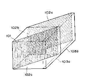
Fig. 5 illustrates an embodiment of the present
invention. A film 101 is provided on a bonding portion
between rectangular prisms 102b, 102c. The film 101
is formed of a multi-layered film or the like such as
a metal thin film and incorporates a function to
separate unpolarized random light into two beams of
linearly polarized light components orthogonal to
each other. A unit generally known as a polarizing
beam splitter is constructed by the prisms 102b, 102c
and the film 101. The polarizing beam splitter is
defined as means for separating the incident light into
two linearly polarized lights.
A rectangular prism 102a is so provided as to
be contiguous to the prism 102b or bonded thereto.
The prism 102a has a bottom face (indicated by oblique
lines) by which the polarized light penetrating the
film 101 of the prism 102b and travelling forwards is
totally reflected. The reflected polarized light is
thereby directed to an optical path parallel to an
optical path of the polarized light reflected by the
film 101. This prism 102a serves as means for causing
the traveling directions of two beams of polarized
light to be coincident each other.
2064669
g
1 ~/2 plates 103a, 103b are so provided as to
tightly contact the prisms 102a, 102c on a path of the
light emerging from the prisms 102a, 102c. Optical
axes of the ~/2 plates 103a, 103b are set to make an
angle of 45~ to each other. The ~/2 plates 103a,
103b are means for arranging the polarizing directions
of two beams of polarized light in an arbitrary
direction.
The operation of this embodiment will be
described with reference to Figs. 6 through 9.
To start with, optical paths are illustrated
in Fig. 6. This Figure is a view taken from above
in Fig. 5. In the same embodiment, the like symbols
represent the same components. The symbols L, P, S
designate beams of light.
Incident light L21 is, as depicted in the
Figure, incident perpendicularly on the surface of the
prism 102c from the left side. This incident light
L21 is random light but unpolarized. The incident
light L21 travels through the prism 102c and reaches
the film 101. The film 101 is designed to the random
light incident thereon with angle of 45~ such that
only light component having a polarized direction
perpendicular to the paper surface of the figure is
reflected while light component having a polarized
direction parallel to the paper surface is transmitted
therethrough. The polarized light reflected therefrom
2064669
-- 10 --
1 is referred to as S-polarized light, while the
polarized light transmitted through the film is
referred to as P-polarized light. In the Figure,
these beams of polarized light are indicated by S21,
P21, respectively.
Traveling directions of the polarized light
S21 and of the incident light L21 are perpendicular
to each other. The polarized light S21 reflected by
the film 101 is emitted from an exit surface of the
prism 102c. This exit surface is provided with a
~t2 plate 103a. The polarized light S21 transmits
through the ~/2 plate 103a. At this time, the
polarizing direction of the polarized light S21 is,
though perpendicular both to the paper surface and
to the traveling direction, rotated about an arrow
of the traveling direction, thereby becoming a beam
of light L22. A function of the ~/2 plate will
hereinafter be described.
On the other hand, the polarized light P
transmitted through the film 101 travels into the
prism 102b. The polarized light P21 is incident on
the prism 102a adjacent to an exit surface of the
prism 102b and totally reflected by an oblique
surface of the prism 102a. Further, an exit surface
of the prism 102a is provided with a ~/2 plate 103b.
The polarized light P21 passes through the ~/2 plate
103b. At this moment, the polarizing direction of the
2064669
1 incident light P21 is, though parallel to the paper
surface but perpendicular to the traveling direction,
rotated about an arrow of the traveling direction,
thereby becoming a beam of light L23.
One of points of the present invention is that
the optical axes of the ~/2 plates 103a, 103b are set
such that the polarizing directions of the light L23
and the light L22 are made coincident each other.
Fig. 7 is a view when observing the ~/2
plates 103a, 103b from a direction of the exit surface.
Broken lines 304a, 304b indicate directions of the
optical axes of the ~/2 plates 103a, 103b. The
symbols u, u', t denote arbitrary points on the
optical axes, and t designates an intersection of the
broken lines 304a, 304b.
According to the present invention, the ~/2
plates 103a, 103b are designed so that ~utu' (angle
defined by points u, t and u') = 45~. In accordance
with this embodiment configured so that ~utu' = 45~,
the beams of exit light - e.g., the lights L22 and
L23 in Fig. 6 - are emitted to assume the same
polarizing direction. The reason for this will be
elucidated with reference to Figs. 8 and 9.
Fig. 8 is a diagram of assistance in explaining
the function of the ~/2 plate. The ~/2 plate, which
is as a kind of phase plate, is manufactured by
polishing a double refraction crystal such as crystal,
206466~
1 calcite, etc.. The square ~/2 plate 103 has tu
which is referred to as an optical axis 404.
Where a linearly polarized light L41 oscillating
in a direction ~41 from the optical axis 404 is now
incident, it can be considered such that the incident
light may be separated into two linearly polarized
light components, i.e., a polarized light (extra-
ordinary ray) L44 oscillating in a direction tu and
a polarized light (ordinary ray) L43 oscillating
perpendicularly in the direction tu. An arrowed
direction is the oscillating direction, viz., the
polarizing direction. If an extraordinary ray
refractive index ne is larger than an ordinary ray
refractive index nO, the optical path length of the
extraordinary ray L44 is longer than that of the
ordinary ray. The ~/2 plate is arranged such that a
phase difference is caused between the two rays after
passing therethrough in this manner, and this phase
difference is set to~ (1/2 wavelength). For this
reason, the two rays become beams of light L44, L45
after the passage, and hence the exit light becomes
a linearly polarized light L42. The lights L43, L45
have the same amplitude, and hence ~41 = ~42. Namely,
the angle between the optical axis and the polarized
diretion of the polarized light before being incident
on the ~/2 plate are made equal to the angle between
the optical axis and the polarized direction of the
206~669
1 polarized light after exited from the ~/2 plate.
Generally, the ~/2 plate, as described above, under-
goes the incidence of the linearly polarized light
having a polarized direction of 45~ to the optical
axis and emits the light whose polarized direction
has rotated by 90~.
A means for arranging the polarizing directions
according to the present invention will be explained
referring to Fig. 9. Illustrated additionally in Fig.
9 to those of Fig. 7 are virtual reference axes x, x',
y, incident lights S21, P21 and exit lights L22, L23-
The axes x, x' are perpendicular to the axis y. The
incident lights S21, P21 respectively indicate the
S-polarized light and P-polarized light, which are the
same as S21, P21 shown in Fig. 6. The polarized
lights travel perpendicular to the paper surface from
the side beyond the paper surface. ~52 ~ ~51 = ~utu'
(angle defined by points u, t and u', where ~51 is
the magnitude of angle constituted by lines tu and x,
and ~52 is the magnitude of angle constituted by lines
tu' and x'.
The explanation begins with 103a. The
magnitude of angle made by the optical axis tu and
the incident light S21 is ~51~ and therefore, as
explained earlier, the magnitude of angle made by the
optical axis tu and the exit light L22 is also ~51
Hence, a magnitude of angle made by y and the exit
2064669
- 14 -
1 light L22 is given by (90 - 2 x ~51)
Next, 103b will be described. A magnitude
of angle made by the optical axis tu' and the incident
light P21 is expressed such as (90 ~ ~52)' and there-
fore, as stated before, a magnitude of angle made bythe optical axis tu' and the exit light L23 is also
expressed such as (90 ~ ~52) Hence, an angle made by
the axis y and the exit light L23 is given by {2 x
(90 ~ ~52)}
The exit light L22 and the exit light L23 may
be collimated for arranging these beams in the same
direction, and hence
90 - 2 x ~51 = 2 x (90 ~52)
Namely
~52 ~ 651 = 45
From this and above-mentioned matters, the angular
magnitude of /utu' is equal to 45~. Namely, when
making 45~ by the two optical axes tu and tu', this
implies that the polarizing directions are coincident
each other.
The incident light defined as the random
light can be generated by a combination of a con-
ventional lamp and a parabolic reflector. According
to the present invention, as obvious from the embodi-
ment discussed above, the exit surface is twice aswide as the incident surface, and hence an aperture
of the reflector can be diminished.
2064669
- 15 -
1 Another embodiment is demonstrated by Fig. 10.
The symbols 601, 602b, 602c correspond to 101, 102b,
102c. The symbols 601, 602b, 602c designate means
for separating the random light into two linearly
polarized lights, i.e. a so-called polarizing beam
splitter. Incident random light L61 is separated into
two linearly polarized light S61, P61 by means of 601-
The light S61 is conceived as linearly polarized light
assuming a polarized direction perpendicular to the
paper surface, while the light P61 is conceived as
linearly polarized light assuming a polarized
direction parallel to the paper surface but perpen-
dicular to the traveling direction.
A mirror 605 is means for causing the traveling
directions of two polarized lights to be coincident
each other. The mirror 605 makes an angle of 45~ to
the exit surface of the prism 602b. An edge of the
mirror contacts a right-angled edge of the prism
602b. This mirror is obtained by polishing an aluminum
material or coating a glass material with a multi-
layered thin film. A reflectivity thereof preferably
approximates to 100 %. If the reflectivity is small,
there arises a possibility of causing a difference in
light quantity between the exit light L63 and the exit
light L62. In this case, a light reducing element such
as an ND filter is provided on the optical path of the
exit light L62, thereby equalizing the light quantities
- 16 - ~ 0 ~ 4 6 ~ 9
1 of the beams of exit light L63, L62.
~ /2 plates 603a, 603b correspond to 103a,
103b and are means for aligning the polarizing
directions of two polarized lights. The function
thereof is as described above. The two polarized
light P61, S61 pass through the ~/2 plates 603a, 603b,
whereby these beams are emitted as exit light L62,
L63 assuming the same polarized direction.
In case of insufficient accuracy of a joining
portion between the mirror 605 and the rectangular
prism 602b and also insufficient accuracy of a
joining portion between the ~/2 plates 603a, 603b,
there appear in some cases splices of illumination
light on a body illuminated with the beams of exit
light L62, L63. In this case, the angle made by the
mirror 605 and the rectangular- prism 602b is not set
at 45~ but may be adjusted several times. For
instance, if set to be smaller than 45~, at least a
part of the exit light L63 is overlapped with the
exit light L62, with the result that the splices are
not conspicuous. Further, a wedge-like glass element
is provided on the optical path of the exit light L63,
at least a part of the exit light L63 is overlapped
with the exit light L62 with the intention of making
the splices inconspicuous. Similarly, the wedge-like
glass element may be provided on the optical path of
the exit light L62 or on the optical paths both of
2064669
- 17 -
1 L62 and of L63.
Still another embodiment is demonstrated by
Fig. 11. The symbols 701 to 705, L71 to L73, S71 and
P71 correspond to 601 to 605, L61 to L63, S61 and P61,
respectively.
In the above-described two embodiments, the
incident natural light is separated into two linearly
polarized lights, and the polarized directions are
aligned after aligning the traveling directions.
In accordance with this embodiment, the
incident light is separated into two linearly polarized
lights, and the polarized directions are aligned in
the same direction when observing them from the
illuminated body, and thereafter the traveling
directions are aligned.
A ~/2 plate 703b is so provided as to tightly
contact with a rectangular prism 702b. Incident light
L71 is separated by 701 into two linearly polarized
light P71, S71 which are emitted from the prisms 702c,
702b and simultaneously transmit through the ~/2
plates 703a, 703b, respectively. At this moment, the
polarized directions of the two polarized lights P71,
S71 are rotated about the traveling direction, thereby
aligning the polarizing directions when being viewed
from the illuminated body.
Optical axes of the ~/2 plates 703a, 703b
are set to make an angle of 45~ to each other when
206~663
1 being projected along the optical path on the
illuminated body.
In the case of this embodiment, the ~/2 plate
703b is interposed between the mirror 705 and the
rectangular prism 702b. Hence, there is a possibility
where the splices become conspicuous on the illuminated
body illuminated with the beams of exit light L72,
L73. In this case, as described above, the splices
are made inconspicuous so as to overlap the beams of
exit light L72, L73
Fig. 12 illustrates a projector using the
polarizing element according to this invention.
The numerals 801 to 803 correspond to 101 to 103.
These components are means for separating incident
random light L81 into two linearly polarized light
S81, P81 and for causing the traveling directions and
polarizing directions to be respectively coincident.
Two-sided arrows with which the linearly polarized
lights S81, P81 are marked indicate the polarizing
directions.
The linearly polarized lights S81, P81
transmit through the ~/2 plates 803a, 803b, thereby
becoming linearly polarized lights L82, L83 whose
polarized directions are coincident each other. This
will hereinafter be explained.
The linearly polarized lights L82, L83 are
incident upon an LCD 806. The LCD 806 is, as in the
206~669
-- 19 --
1 same way with the conventional example, constructed
such that an orientation of the crystal is inclined
to the end of the LCD by 45~. This LCD is separated
into a multiplicity of pixels. Further, a multi-
plicity of liquid crystal molecules are arrayed inthe respective pixels. In accordance with input
signals, the array of the liquid crystal molecules
varies per pixel, and an image modulation is effected
by rotating the polarizing direction of the polarized
light. The light undergoing the image modulation is
detected as necessary optical information L84 by means
of an analyzer 807. The light is then projected on
an unillustrated screen by a projection lens 811.
The analyzer 807 involves the use of a polarizing
plate, a polarizing beam splitter and the like.
A light source is not illustrated in this
embodiment. However, as in the prior arts, a combi-
nation of the lamp and the reflector or a laser CRT
may be thinkable as a light source.
A color projector may be provided by following
manner.
Interposed also between the ~/2 plate 803 and
the LCD 806 is color separating means which employs a
material such as a dichroic film or halogram exhibiting
a wavelength selectivity, for separating the white
light into respective color components R, G, B. The
LCDs are provided corresponding to the respective color
206~L669
- 20 -
1 components R, G, B. A color synthesizing means for
synthesizing the respective color components R, G, B
which have undergone the image modulations by the LCDs
is disposed between the LCD 806 and the analyzer 807
or between the analyzer 807 and the projection lens
808. A color projector is thus attainable. Besides,
the effects may be exhibited not only by the 3-color
separate synthesization of R, G, B but also 2-color or
multicolor separate synthesization.
The following is an explanation of the A/2
plates 803a, 803b with reference to Fig. 9.
The ~/2 plates 803a, 803b correspond to 103a,
lb3b. In addition, the polarized directions of the
polarized lights S81, P81, L82, L83 corresponds to those
~f S21' P21' L22' 23
In the LCD 806, the liquid crystal is oriented
in a direction inclined at 45 degrees to the end
portion of the LCD shown in the conventional example.
Therefore, the linearly polarized light assuming such
the polarized direction is required. Namely, the
polarized directions of two linearly polarized lights
S21, P21 orthogonal to each other are respectively
rotated by 45~, and the optical axis of the ~/2 plate
is set so that these beams are emitted as L22, L23.
Consequently, a required illumination of the linearly
polarized light can be obtained.
As obvious from Fig. 9, if 2~51 = 45~ and
2o~669
- 21 -
1 2 (90~ ~ ~52) = 45~l the beams of light S21, P21 are
rotated through 45~, thereby becoming L22, L23. At
this moment, ~51 = 22.5~ and ~52 = 67.5~. This, as
explained before, satisfies the angle utu' = ~52 ~ ~51 =
45~, where utu' is the angle made by the two optical
axes.
Note that the present invention is not limited
to the embodiments discussed above. A variety of
constructions are, as a matter of course, possible
within a range which does not depart from the gist of
the invention. For example, the two luminous fluxes
from the polarizing illumination system are not
necessarily parallel to each other. An angle made
by the two luminous fluxes may be given by changing
the angle of the total reflection surface of the
rectangular prism 102a of Fig. 1 or the angles at which
the mirrors 605, 705 are inclined or disposing a
wedge-like glass element in at least one optical path.
Further, as means for separating the incident light
into two linearly polarized light, i.e., the P-
polarized light and the S-polarized light, the
following members may be employed separately depending
on the purposes. These members are not only the
polarizing beam splitter shown herein but also a double
refractive lens made of an optically uniaxial material
represented by an embodiment which will be described
later. These members further include those capable
206~669
- 22 -
1 of separating the incident light into a pair of
polarized light beams orthogonal to each other such as
a Glan-Thompson prism, a Wollaston prism and a Rochon
prism.
S Fig. 13 is a sectional view depicting a part of
another embodiment of the polarizing element acording
to the present invention.
Designated at 1313 is a lens array in which a
plurality of cylindrical lenses each composed of an
optical material exhibiting a double refractivity are
arranged within the same plane. Indicated at 1303a,
1301b are ~/2 plates each made of an optically active
substance.
The cylindrical lens 1313 is composed of the
optical material exhibiting the double refractivity to
have an ordinary ray refractive index nO in an intra-
paper-surface-direction and an extraordinary ray
refractive index ne in a direction perpendicular to
the paper surface.
The incident surface has a curvature of l/r,
while the exit surface is plane. In such a condenser
lens, a focal distance is given approximatively by fO =
r/(nO ~ 1) with respect to the normal ray and by fe =
r/(ne - 1) with respect to the extraordinary ray. In
accordance with this embodiment, ne ~ nO
Of parallel beams (a) of the random light,
luminous fluxes of component assuming the
- 23 - 2 0~ 6~9
1 intra-paper-surface polarizing direction are condensed
at a position of the focal distance fO as normal rays,
while luminous fluxes of component assuming the
polarizing direction perpendicular to the paper surface
are condensed at a position of the focal distance fe
as extraordinary rays.
The ~/2 plate 1303a has a slit 1314a disposed
in the condensing position of an extraordinary ray Le.
On the other hand, the ~/2 plate 1303b has a slit
1314b disposed in the condensing position of an ordinary
ray Lo. These slits 1314a, 1314b serve to eliminate
the optical rotatory power on the respective extra-
ordinary and ordinary rays of the ~/2 plates 1303a,
1303b.
The optical axis of the ~/2 plate 1303a is
set at 22.5~ to the paper surface. For this reason,
the ordinary ray Lo undergoes action of the ~/2 plate
1303a when passing through the ~/2 plate 1303a and
thereby becomes a linearly polarized light L assuming
such a polarizing direction as to make 45 degrees to
the paper surface. On the other hand, the extra-
ordinary ray Le passes through the slit 1314a and
therefore undergoes no action of the ~/2 plate 1303a.
The optical axis of the ~/2 plate 1303b makes
an angle of 67.5 degrees to the paper surface and set
at 45 degrees to the optical axis of the ~/2 plate
1303a. For this reason, the extraordinary ray Le
206~669
- 24 -
1 undergoes the action of the ~/2 plate 1303b when
passing through the ~/2 plate 1303b and thereby
becomes a linearly polarized light L assuming such a
polarizing direction as to make 45 degrees to the
paper surface as in the same way with the ordinary ray
Lo. On the other hand, the ordinary ray Lo which has
previously been subjected to the action of the ~/2
plate 1303a travels through the slit 1314b and there-
fore undergoes no action of the ~/2 plate 1303b.
As shown above, if the optical axes of the ~/2
plates 1303a, 1303b are set to make substantially 45
degrees when being viewed from the side of the exit
light, both the extraordinary ray and the ordinary ray
can be converted into linearly polarized lights
assuming the same polarizing direction. Thereafter,
when the optical axes of the ~/2 plates 1303a, 1303b
are set within the range which does not depart from
the conditions thereof, it is possible to obtain the
linearly polarized light assuming a desired polarized
direction other than the polarized direction which
makes 45 degrees to the paper surface as shown in this
embodiment.
This embodiment deal with the luminous fluxes
of incidence as a plurality of luminous fluxes, wherein
the luminous flux is incident per unit element. When
increasing the number of divisions, an effect of
reduction in size can be expected. Hence, a distance
- 25 - 2064669
1 from the light source to the LCD can be decreased,
thereby improving a condensing efficiency of the
illumination light.
Besides, the respective gaps between the
members 1313, 1303a, 1303b are presumed as air gaps.
However, glass or the like is sealed thereinto to
form these members into one united body. Alter-
natively, a fly eye lens may be used in place of the
cylindrical lens 1313. In this case, however, 1314a,
1314b will be not the slits but pin-holes. Further,
as a matter of course, it is possible to adopt such a
mode that the cylindrical lens 1313 is not arrayed but
may be constructed as a single birefringence lens.
In accordance with this embodiment, the exit
surface of the cylindrical lens is formed as a plane
surface. However, the incident surface may be plane,
and a lenticular lens having curved surfaces on both
sides may also be employed. In addition, a Fresnel
lens may be used as a condensing means which employs
the optical element exhibiting the double refractivity.
The polarizing element in this embodiment is constructed
as a compact plate type element and is therefore
suitable for the projector. Besides, the polarizing
element can be, because of its being compact, provided
per LCD corresponding to each color of a color
projector. The ~/2 plate having the wavelength
dependency can be constructed for every color, and
2064669
- 26 -
1 hence it is feasible to increase a photo utilizing
efficiency and actualize a good color reproducibility.
Fig. 14 is a sectional view showing a part of
still another embodiment of the polarizing element
according to the present invention.
In this embodiment, a lens array 1413a and a
double refractive plate 1413b are employed as a
condensing means using the optical element exhibiting
the double refractivity in the polarizing illumination
system. ~/2 plates 1403a, 1403b are the same as those
in the previous embodiment. A lens array 1413a is a
lens made of an isotropy optical material having a
refractive index n; and its focal distance is expressed
such as f = r/(n-l), where the curvature of the incident
surface is given by l/r. On the other hand, the double
refractive plate 1413b is composed of a double
refractive optical material to have an ordinary ray
refractive index nO in the intra-paper-surface
direction and an extraordinary ray refractive index ne
in the direction perpendicular to the paper surface.
An incident luminous flux (a) is condensed by means of
the lens array 1413a, wherein the focal distance f =
r/(n - 1). Because of providing the complex refractive
plate 1413b, a condensing position deviates by ~o =
d (1 - l/nO) with respect to the ordinary ray on the
exit side and by Ae = d (1 - l/ne) with respect to the
extraordinary ray on the exit side (where d is the
206~669
1 thickness of the double refractive plate 1413b). The
~/2 plates 1403a, 1403b each formed with a slit or
pin-hole are disposed in the respective focusing
posltions .
The operation of this embodiment is the same
as that of the preceding embodiment, and the description
thereof is omitted. According to the present invention,
it is not required that the double refractive member is
processed anew into a lens array, and hence the costs
can be reduced. In the embodiments discussed above,
the polarized directions are rotated by transmitting
two linearly polarized lights through the ~/2 plate.
However, a ~/4 plate admits two linearly polarized
lights and again transmits the light via a reflection
member, so that the exit light whose polarizing
direction is rotated can be obtained. Namely, in this
case, the light beams are caused to transmit the ~/4
plate twice through the reflection member, thereby
giving the same function as that of the ~/2 plate.
Further, the same effects are acquired not only by the
phase plate but also by other substances such as a
liquid crystal exhibiting the optical rotatory power.
The present invention is applicable to all devices such
as an automobile head light requiring the linearly
polarized light other than devices such as a liquid
crystal printer head using a liquid crystal-optical
shutter in which the LCD is irradiated with the light.
206~669
- 28 -
1 As explained above, according to the present
invention, the polarized directions of two linearly
polarized light can be matched with the orientating
direction of the liquid crystal by use of a single
phase plate for one optical path. It is therefore
possible to obtain the polarized illumination light
having a good photo utilizing efficiency in an
arbitrary polarized direction. Besides, the number
of factors for matching the angle of the optical axis
of the phase plate during the manufacturing process
is decreased. The color imbalance and the surface
reflection of the phase plate can be minimized. This
in turn makes it possible to obtain the polarizing
element the costs of which are reduced more remarkably
than in the prior arts.
The projector according to the present invention,
presents such merits that the LCD can be illuminated
with the linearly polarized light assuming the
polarized direction having the angle optimal to the
orientation of the liquid crystal and other various
conditions; and the bright image with a high contrast
but with no ununiformity can be provided.
Although the illustrative embodiments of the
present invention have been described in detail with
reference to the accompanying drawings, it is to be
understood that the present invention is not limited to
those embodiments. Various changes or modifications
206~669
- 29 -
1 may be effected therein by one skilled in the art
without departing from the scope or spirit of the
lnvention .