Note : Les descriptions sont présentées dans la langue officielle dans laquelle elles ont été soumises.
WO9l/02~50 PCTJDK9n/00208
2~6~
Process and plant for producing heat treated growth
substrate and manure.
The invention relates to a process and a plant for
producing a heat treated natural manure material or a
fertilized enriched substrate material ready for use. In
connection with the invention is preferably referred to
a substrate on basis of so-called coco dust or coir
dust, which is a waste product from the production of
coco fibres, but the invention is not limited thereto,
as the material can also be sphagnum or other biological
substrates as well as purely natural manure, e.g. poul-
try manure. In natural substrate materials there usually
happens to be a rather high quantity of weed seeds and
insect eggs, which are unwanted by most usages of the
substrates, and as there can also be unwanted bacteria
and fungi it has been proposed to subject the substrates
to a heat treatment before delivery to the users, which
mainly are nurseries. Something similar applies to pure-
ly natural manure materials.
The heat treatments used hitherto have, however,been rather expensive and not too efficient and general-
ly they have not left the experimental stage. Moreover,
while many difficulties are avoided by the use af a
2S pasteurized substrate, the substrate will be highly
vulnerable to intrusion of new and undesired microbiolo-
gical matter, so even the experimental use has not pro-
duced too valuable or reliable results.
It is the primary object of the invention to provi-
de a process by which the treatment can be carried outin an industrial sense, both more effectively and much
less expensively.
For an industrial heat treatment it is well known
to use a flow-through kiln with a perforated revolving
drum to which heat is led form an external fixed kiln
jacket, and with the invention use is still made of such
R~:D~ C.r~~ T~ ~e
WO9l/02~50 PCT/DK90/00208
2~6~7~0
a Xiln. Care is taken, however, that the outflow of
material passes through a heat insulated 20ne so that
the effective time of treatment for a given heating
effect can be prolonged. Said closed passing zone is
continued in a closed cooling zone, and, in case of
substrates, further through an admixing station for
fertilizer substance and microbiological matter and
still further to a delivery station, preferably a bag
filling station, altogether in a closed system. Hereby a
very high degree of utilization of the supplied heating
effect is obtained so as to achieve a pasteurization of
the material, and the achieved high purity of the mate-
rial is maintained altogether until the material is
delivered to closed containers, e.g. sacks namely due to
the said closed system. It is undesirable to deliver the
material in hot condition, as also certain fertilizer
substances can be damaged by too high a temperature, and
therefore the said cooling is used, which can be carried
out in a simple manner by a through-blowing of air,
which air should only be scantily filtrated. construc-
tionally a relatively short conveyor to the delivery
place can then be used, as the material shall not cool
off by itself during the transportation.
For a good and homogeneous result it is furthermore
2S of importance that the material is transported in a
well-controlled manner through the kiln zone, and accor-
dingly an especially designed feeding system is used, by
which this is achievable.
It has been found that the structure or texture of
the sphagnum material thus treated is highly improved
for growing purposes, the structure being changed in the
direction of a more crumby material, which is highly
advantageous for the plants e.g. by exhibiting a remark-
ably reduced collapsing tendency. The formation of the
crumby structure is favored by keeping in the ~iln prac-
tically all moisture or s~eam developed during the heat
WO91/02550 PCT/DK90/00208
2~6~7~0
treatm~nt of the material, this also accounting for a
very efficient pasteurization. At least as far as sphag-
num is concerned it i5 not desired to dry the material,
so it may leave the kiln as moist as it was supplied.
Plants have been observed to grow and develop much
better in the new material, and a remar~able decrease of
the conductivity value has been measured, this being
significant to experts in the art.
The sphagnum raw material is always available, but
it is supplied from different source areas, whereby its
quality and microbiological properties may vary. The
users cannot rely on the quality being unchanged for
each new shipment, and also for that reason the sphagnum
material is not used as much as it could deserve, in
view of the relatively low price and the good quality
aspects thereof. However, when treated according to the
invention the sphagnum quality is raised to an almost
uniform level for the various types of the material, so
the treatment can be effected continuously and the users
can rely on the delivery of a practically uniform high
quality product through all seasons.
A very important aspect of the invention is that
the quality of the product is further increased by a
controlled introduction of certain fungal and bacterial
25 species which will protect the substrate from intrusion
of exterior dangerous biological matter at the site of
use and condition a perfect growth of the plants. Some
useful species have already been found, sufficient to
make the product applicable in large scale use, but it
is to be admitted that a very large research work is
still to be done for perfectioning the product, e.s. in
a selective manner for different plants.
Seen on this background another important aspect of
the invention is to provide a basic condition for such
an important research work to be carried out at all,
because a research carried out at laboratory conditions
REPI_J;CeMENTSHEFr
WO91/025~0 - PCTIDK90/00208
206~7~0
will not be representative for actual practice.
The invention is described in more detail in the
following with reference to the drawing, in which:-
Fig. 1 is a perspective view of a complete treating: 5 plant according to the invention,
Fig. 2 is a cross sectional view of a flow-through
kiln of said plant, and
fig. 3 is a cross sectional view of an aftercoupled
treatment unit.
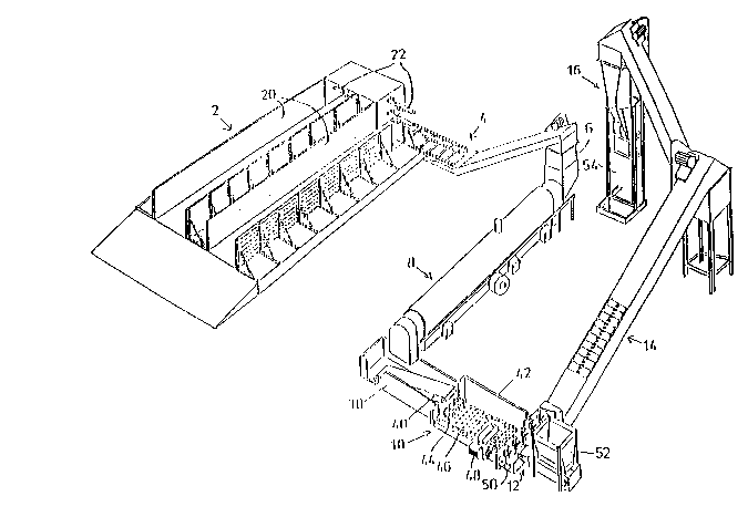
, 10 The plant shown in Fig. 1 comprises as main parts a
silo plant 2 for reception of natural substrate materi-
al; a conveyor 4 connected therewith for feeding of the
material to a receptacle 6; a succeeding pasteurizing
kiln 8, the outlet of which the material is conveyed to
an admixer station 12 for fertilizers; and a conveyor 14
which transports the material to a delivery station 16,
from which the material can be delivered e.g. packed in
sacks.
The silo plant 2 comprises two plane silos 20 each
of which (in the left-hand side) is shaped with an open
reception end for a substrate, and which in a manner not
shown is equipped with a bottom plate which can act as a
forwardly moving conveyor belt for feeding the material
towards the opposite, closed ends of the respective
silos, where the transverse conveyor 4 will pass the
material to the kiln 8. At the delivery end of the silo
units 20 are placed transverse scrape-down rotors 22
which will loosen the supplied material to fall down on
the conveyor 4. The for~ard pushing of the material in
the two shown silo sections is made alternating in such
a manner that one silo section is emptied, while the
other is inoperative, i.e. only disposed for reception
of material by driving in the m~terial through the asso-
ciated open drive-in end, which is shown in the
left-hand side, and accordingly a filling in can take
place in one silo section while the contents in the
~DI ~ IT~E~
U'091tO2S50 PCT/DK90/00208
20~7~
other silo section is be~ng emptied.
In the receptacle 6 as indicated in Fig. 2 there is
placed a level detector device 24, which detects the
~aterial level in the receptacle and effects a stopping
of the conveyor 4 as long as an over-filling of the
receptacle 6 over a preset standard level might be de-
tected. From the lower end of the receptacle 6 a conti-
nuous feeding of material into the kiln takes place, the
lower end of the receptacle 6 being provided with a
driven helical conveyor 26 in open connection with the
feeding end of the tubular flow-through ~iln 8. The
level detector and the helical conveyor cause the forma-
tion of a material-plug at the inlet to the kiln and
thereby prevent a return flow of gas in the system.
The Xiln 8 is provided with a perforated kiln drum
28, which by means not shown is supported in a rotatable
manner and is equipped with axially extPnding inwardly
protruding wing parts 30, which by rotation of the kiln
drum 28 wiIl agitate the material, this then being
transported forwards as the kiln is declined towards the
outlet. At the bottom of the kiln 8 is placed a number
of gas or oil burners 32 which deliver heat to the space
between the outside of the kiln drum 28 and a surroun-
ding heat insulating kiln jacket, 34 such that the heat
therefrom penetrates into the perforated kiln drum, as
at the middle of the kiln there is placed an upper ex-
haust 36 for giving off the supplied combustion gas and
the contents of water vapour therein. Considerable a-
mounts of water vapour will be involved not only from
the combustion, but especially from the resulting water
drive off from the manure or substrate material which
initially typically contains approximately 20% water or
approximately 14 kg water per m3. By a plant of a prac-
tical, preferred size this means a vapour outlet corre-
sponding to 450 kg water per hour.
However, for certain materials such as sphagnum, it
;
WO911~2~50 PCT/DK90/00208
6 2~6~7~0
is not desired to dry the material, because the saidcrumby structure could then be compromised, and in that
case the exhaust can be kept more or less closed. It
will be appreciated that the vapour and steam cannot
escape freely through the ends of the kiln; during the
operation on equilibrium will be reached between vapour
delivered from and readsorbed ~y the material.
At the delivery end of the kiln 8 the material is
delivered to the station lO, namely by dropping down in
a first section 38, which contains an upwardly inclined
conveyor belt 40 and moreover is closed and heat insula-
ted. In this section the material is transported relati-
vely slowly and in a thic~ layer on the belt 40, i.e.
the material will to a great extent maintain the tempe-
rature, to which it has been heated in the kiln 8,
whereby the heat treatment of the material will be ex-
tended without additional energy consumption. The tempe-
rature, however, will decline towards an inefficient
level, and the material will then at the upper end of
the conveyor 40 be transported through a restricted slot
at the ceiling of the station 38 and fall down in the
following unit designated 42, which is a cooling unit in
which the received falling down material hits a grater
roller 44 and therefrom is led onto a conveyor 46, which
is relatively fast moving such that the material is
deposited in a thin layer thereon, and which is penetra-
table by cooling air delivered from a lower fan 48.
Hereby it is possible to obtain a rapid cooling of the
material, which on the conveyor 46 is transported to the
admixing station 12, in which a cross-delivering wingro-
tor 50 is situated, the latter receiving substrate from
one side, while from the opposite side it receives a
fertilizer or a mixture of such additives. The rotor 50
causes an intensive mixing of substrate and additives
and conveys the material further on the the upwardly
inclined conveyor 14.
Rf~PL ~ F~
WO91/02~0 PCT/DK~0/00208
2~647~
It should be endeavoured that the mat~rial is de-
livered from the ~iln 8 at a temperature not below 90
C, and preferably at the delivery end of the kiln there
is placed a temperature sensor, which by detection of a
lower temperature causes an actuation of the dri~e means
for rotation of the kiln drum 28 in such a manner that
the run through velocity is reduced accordingly for
achieving a higher temperature.
The delivery or sack filling station 16 does not
, lO need closer description, it should only be mentioned
that optimally it should be a closed unit which received
the final ~anure or substrate mixture from a closed
conveying system 14 in such a manner that the delivered
mixture can be filled in sac~s 54 without the mixture
having been exposed to reception of seeds or other ex-
ternal impurities after the heat treatment.
It is to be preferred that the flow of material
through the kiln is controlled in such a manner that at
the delivery end of the kiln there is achieved a mate-
rial temperature which is close to 100C, preferably
between 90C and 100C, as a totally efficient heat
treatment demands at least 80C while conversely a hea-
ting to over 100C will imply an undue overuse of energy
and a possible damage of the material. The use of the
mentioned inlet lock with the level sensor 24 will con-
dition a well controlled flow to the kiln, and besides
the time of flow-through can be varied in different
manners, including more generally by an adjustment of
the kiln in a more or less inclined position.
The invention is described a~ove as particularly
relevant for substrate materials but it will be under-
stood that it is in actual fact just as relevant as far
as pure manure products or other goods are concerned,
when these should not be enriched by additional adding
of fertilizers.
As mentioned, it is highly preferably or even nece-
_ _ _ . _ . ..... _
WO91/0~0 ~ PCTIDK90/00208
8 206~7no
ssary to add some species of fungi and bacteria, which
can suitably be done in the mixer station 12. It is one
of primary importance to enrich the pasteurized material
with such species, which will protect against later
intrusion of dangerous cultures, and for general use the
fungal species trichoderma harzianun, pythion oligandrun
and gliocladiun virens will be advantageous. Also seve-
ral bacterial species will be suitable, one being bacil-
lus streptomyces, which is already known to be natural
, 10 antibiotics. However, further details in this respect
will be a matter of scientific and practical research.
.