Note : Les descriptions sont présentées dans la langue officielle dans laquelle elles ont été soumises.
206511~
METAL UTENSIL
The invention relates to metal pots and pans, containers and/or lids,
intended more particularly for use as cooking utensils. The metal utensils
are formed into a utensil system as a result of their specific shaping.
Cooking utensils are generally multipurpose utensils and must therefore have
5 a wide spectrum of characteristics. More particular significance is attached
to characteristics such as the chemical and mechanical resistance of the sur-
face, safe and easy handling (ergonamy) so as to keep accident risks low
when cooking, together with the shape of the utensil adapted to the partic-
ular cooking function and the ease of cleaning. Significance is also atta-
10 ched to the thermal characteristics (material and material cambinations) ofsuch a utensil and finally r~bustness and at the same time a low weight. It
is to be assumed that all these characteristics cannot be cambined in opt-
imum manner in a single utensil and therefore every utensil is to a certain
extent a campromise.
15 Cleanness or hygiene requirements make it impossible for such utensils to
have difficultly cleanable points such as joints, e.g. on and around handle
and grip attachments. Normally such grips are attached to the outer wall
of the utensil, either by rivets, or by a soldered/welded joint. In many
cases the handles are a relatively limited distance above the heat source,
20 so that they can easily become heated. Utensils used in commercial kitchens
are not thermally insulated at the handles, so that such insulating mater-
ials cannot suffer as a result of the heat or the rough handling in such
kitchens. Such vessel handles are bulky and do not allow a space-saving
stacking of the cooking utensils. This makes difficult or even impossible
25 bain marie or double saucepan cooking with cooking utensils of different
sizes fitted in one another.
A metal utensil having handles not suffering from such disadvantages and
also having further advantages would be desirable and is brought about by
the invention described hereinafter.
3 The invention shows how a metal utensil with hand grips or handles shaped
out of the marginal part of the utensil can be manufactured in simple,
material-saving manner. Such a utensil can be used in a much more universal
manner than conventional cooking utensils.
~,L.
206511~
.
Information already exists on the provision of vessel handles mainly on non-
metallic cooking utensils, but in the case of metallic utensils this has not
proved successful for different reasons. Thus, German Utility Model G 90 01
134.1 discloses a utensil having a shaped on rim, which cooperates with the
lid and which is also constructed for grasping and picking up. These
vessels are made fram ceramic, glass or plastic and are mainly intended for
use in microwave equipment. A simil~r construction is disclosed in W~
90/09133 of the same Applicant, namely a metal cooking utensil, but the
shaped on part only serves as a pouring rim or edge. For handling purposes
such utensils have the usual vessel grips or handles. This utensil also
co~perates with the lid so as to allow a better pouring off of the boiling
product.
In neither case is there a shaped on vessel handle, althaugh it would lead
to considerable advantages. With such a handle in the case of metal uten-
sils the aforementioned disadvantages wou~ be avoided and additional advan-
tages obtained. Importance is also attached to the stability of the utensil,
particularly the container, whose strength in the hot and cold state and
during loading through handling when cooking must always be adequate. How-
ever, this cannot be brought about by the utens;l or parts thereof being
made frcm very thick sheet metal in order to ensure such strength. For
example with stainless steel, the disadvantages would be the poor thermal
conductivity and high weight, whereas in the case of light metal the limited
strength and the surface unprotected against discolouration and oxidation.
In this connection the invention uses for the entire cooking utensil a
laminated material, whose structure corresponds to the bottam parts of con-
ventional stainless cooking utensils. The laminated materials can be con-
stituted by relatively thin, stainless steel sheets cambined with a gocd
heat conducting metal, e.g. aluminium in a thickness with which the strength
deficiency of thin steel sheets is compensated. The resulting improved heat
distribution not only extends to the bottam part, but to the entire surface
of the cooking utensil. In this way a fully encapsulated system utensil is
obtained.
This leads to the two advantages of a gocd heat distribution through the
core material, e.g. aluminium and increased strength resulting fram the
206~
plating of thin, stainless sheets. As a result of its strength, this makes
it possible to shape randcm handles and grips from the utensil edge or rim
allowing the special shaping of the handle attachments for a system utensil
with e.g. improved stackability, reciprocal usability, e.g. bain marie
S cooking and more universal usage, e.g. as a steaming, sieving or pouring
vessel. Through shaping and using heat distributing laminated materials,
- a local overheating within the vessel is virtually impossible. As the lamin-
ated material is characterized by high strength, the handles can be extended
further outwards, so that they are positioned cutside and well above the
heat scurce and do not get in the way on fitting the vessels in one another.
The invention is described in greater detail hereinafter relative to non-
limitative ~mk~im~nts and the attached drawings, wherein show:
Fig. 1 In parts A to D the basic manufacturing process of a metal
utensil accor~;ng to the invention.
15 Fig. 2 In two parts A and B partly in elevation and in section a fully
encapsulated utensil, namely a container and a matching lid,
part B showing a possible embcdiment of the handles seen in the
direction of the centre of the container.
Fig. 3 The utensil according to fig. 2 frcm above, i.e. viewing the lid.
20 Fig. 4 Four containers placed in one another having different diameters
and displaced handles, viewed frcm above.
Fig. S A successive projection of the handles of the stacked containers
according to fig. 4 showing the characteristic nature of such
a system utensil.
25 Fig. 6 The cooperation between the container and lid, the latter being
raised.
Fig. 7 The cooperation between the container and the li~, the latterbeing kept flat, which again shows the system character of the
utensil.
2~65115
Fig. 8 Diagrammatically and based on figs. 5, 6 and 7, the possibility
of vertical variations, made possible by the shaping of the
handle attachments on the vessel rim.
Fig. 1 shcws in the sequence A to D relative to the formation of a material,
in this case a laminated material (fig. lA), which comprises a gocd heat
- oonducting core material 2 and thin stainless steel 1 plated on either side.
The laminated material is e.g. cut to size as a square plate (fig. lB) and
is deep drawn in this form. The deep drawn part (fig. lC) with the still
uncoated rim 5 and the vessel interior 3 appears fram above in the manner
shown in fig. lD. The drawn in profile line 6 illustrates the subsequent
cutting of the edge or rim of the vessel, together with the handle attach-
ments. The waste 8 resulting fram the cutting cperation is smaller by the
material of the surfaces for the handle attachments 12 than with conven-
tional circular vessels. Fundamentally such a container can also be used
as a lid (raised lid) or in other words, with respect to the shaping, a lid
is manufactured in the same way as the vessel. Fram the shaping standpoint
there need be no difference between the lid and the cantainer of a utensil
according to the invention. Laminated materials are used for the manufac-
ture of the vessel parts of the utensil, whereas, although this is not
prescribed, the lids are generally made frcm a single-layer material.
The preliminary prcduct for the manufacture of a utensil according to the
invention is characterized by its special shaping, the handle attachments
12 being subsequently shaped anto a vessel blank. The blank here comprises
a laminated material consisting of three layers, namely outer layers 1
(surface layers) and a central layer 2 positioned between them (heat conduc-
ting layer). The surface layers are preferably made frcm a material, which
in an optimum manner meets the surface reguirements and the heat conducting
layer is made from a material, which in an optimum manner meets the heat
sLo~age and distribution requirements. These individual layers are cambined
by a known process to form a starting material. The surface layers can be
made frcm high-quality steel which, as a thin sheet in the ccoking utensil,
externally and internally protects the surface, whereas the heat conducting
layer can be made fram a good heat conducting material, e.g. aluminium which,
as a correspondingly thicker sheet in the cooking utensil, stores and
206511~
distributes heat. Ccmpared with aluminium high-grade steel is a poor heat
conductor if it were used in a thickness which wculd give the utensil the
necessary stability to enable the shaping of handles on the marginal portion
of the utensil and in this case the uniform heat distribution in the utensil
5 woulA be inadequate and the weight too high and if this was brcught about
by heat storing aluminium only then the surface characteristics would be
inadequate and the utensil would also have a much lower s~l~nyU~ than when
ccmbined with high-grade steel.
Unlike in the case of cooking utensils with encapsulatéd bottcms this
10 c~oking utensil is fully encapsulated except for the handles. This can be
seen in fig. lC which, following a deep drawing pr~cess, shc,ws such a fully
encapsulated utensil with an inner area 3. Part;oll~r reference is made to
the fact that through the handle attachments fitted in the corners of the
starting material, material can be saved, there is less waste and no addi-
15 tional material is required for the handle fixing fittings, which has a cost-saving action in view of the expensive starting material. As a result of
the shaping of the handle attachments 12 (figs. 2A and 3) on the blank,
during the subse~uent processing to the finished product, it is possible to
econcmize certain operations serving solely a handle fitting function. Thus,
20 this measure leads to a cooking utensil requiring less material and labour
costs and which also has better characteristics with respect to the utensil
gecmetry and heat balance.
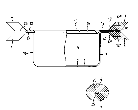
Fig. 2A shows in section such a utensil with a vessel lO (as the end prcduct)
with an engaged, associated lid 15, in which the two handles 4 are fixed to
25 the vessel rim extension 12. There are possibilities for the shaping of e.g.straight extensions (12 on the left-hand side of the drawing) or bent exten-
sions (12/12'/12" on the right-hand side of the drawing), which form the
handle attachments. There are no limitations with respect to this shaping,
in the same way as handles riveted or welded to a similar vessel. Any
30 randcm configuration can be given. The handle attachments 12 according to
the invention must be produced in the same operation as the vessel, but
still have the described advantages in spite of the savings. The handle
attachments 12 (or 12/12'/12n) for the vessel handles 4 are shaped in the
same way on the lid, but here without using an encapsulated material.
2 ~ 6 3 1 1 5
Fig. 2B shows a special shaping of the vessel handle 4, namely either with a
trough-shaped depression or a spherical protuberance, both designated 25.
When the handles are engaged on one another, they prevent recipr~cal dis-
placement between the lid and the container and space the vessel 10 and lid
5 15 frcm one another for forming a pouring and steaming cpening. This
special shaping (depression/protuberance) can also be fitted on the handle
- attachments 12, 12' or 12" for fulfilling the same function.
Fig. 3 shows the utensil according to fig. 2 fram above. It can be seen
that the shaping for the vessel and the lid ca-n be the same. As the lid
10 d oe s not have to satisfy the same requirements regarding strength and heat
distribution, it is mainly a question o its shaping within the system
gecmetry. The logical shaping for system utensil purposes is made apparent
by the fact that when viewed fram above the vessel without the lid appears
the same.
15 Fig. 4 shows four vessels fitted into one another, which are of the same
type but of different sizes. The individual containers have the external
diameters D1 to D4, the handles are designated 12.1 to 12.4 and between the
handle attachment 12 and the handle 4 (fig. 3) no distinction is made at
this point. On the top of the handles it is possible to see the depressions
25, in which can be inserted the matching protuberances on the lid handle.
This detail has already been discussed in conjunction with fig. 2B.
These utensils are inserted in one another up to the vessel rim, as is shown
by a detail according to fig. 5. Fig. 5 shows in a successive projection
of the handles of the stacked cantainers accor~;ng to fig. 4, how the latter
can be placed in one another. The characteristic nature of this system
utensil is also readily apparent. Such a space-saving stacking woUl~ not
be possible with handles not fixed to the vessel rim. Numerous further
possibilities regarding handling and ergonamy result from these character-
istics and can be constantly extended through the use of such vessels. The
space-saving stacking extends to such an extent that the volume of such a
utensil set corresponds to the volume of the largest vessel.
Figs. 6 and 7 show possible constructions of the vessel handles of vessel
206~115
..
and lid in such a way that they can together ass~me special functions. If
the vessel and lid handles are superimposed, so that the protuberances 25
are engaged in the depressions 25, the lid rim is raised frcm the vessel rim.
In this position the lid can be tilted over rotation points formed by the
5 spheres in the depressions 25, so that between the lid and vessel rim on one
side a pouring or sieving opening is formed and on the other side a venti-
lating gap.
Fig. 6 shows a variant with a raised lid 5, which is placed on the container
10. Frcm the shaping standpoint the lid 15 can be fundamentally the same as
the container 10. As a function of the thenmal and/or stability requirement
it is either p mduced only from a sheet material with shaped on handle
attachments, or from a laminated material in the same way as the container
and in this case can be used as a cooking utensil. This fundamental simil-
arity is represented by the same reference numeral 3 for the inner area of a
lid or a container of the utensil. The height of the raised lid can have a
randcm depth and in itself forms a container, because the handle arrangement
of the openings of the container and the lid can be the same. As regards
shaping there is no significant difference between the container and the
1;~, the materials to be used for prcduction differing only as a result of
the different uses.
Fig. 7 shGws a variant with a flat lid 15 or in other words with a smaller
inner area 3. In this form the lid can scarcely be used as a container and
it is usually only made frcm a single sheet (not laminated material) with
shaped on handle attachments. However, here again there is symmetry at the
container cpening as a result of the shaping to a system utensil.
Both lid variants of figs. 6 and 7 have the same handle requirements. The
spherical protuberance 25 on the underside of the lid handle 4 and the
trough-shaped depression 25 on the tcp of the vessel handle permits an
engagement of the lid in a raised position with respect to the container, so
that as a result of a lid tilting movement on one side a pouring and sieving
opening is formed, whilst on the other side a ventilation gap is formed.
This is only poss~ble because the handles are directly fitted to the marginal
part of the utensil and are consequently arranged with the correct relation-
206511~5
ship to the lid handles. It is also apparent that the vessel handles on theupper vessel rim or the marginal part of the vessel are precisely in the
correct location for obtaining numerous advantages. If the handles are not
superImposed, then the cooking vessel is sealed by the lid resting directly
5 on the vessel rim.
- If the lid shaping, in the manner shown in fig. 2A, is chosen in such a way
that the lid surface 15 is constructed as a plane, it becames possible to
place an such a lid a second cooking vessel for keeping hot and energy
saving purposes. This is once again only possible because the lid handles
10 and also the vessel handles are located on the marginal portion and there is
no centrally positioned lid grip.
As is shown by the reference numeral 16 in fig. 3 and in the sectian of figs.
6 and 7, lids constructed in a plane can be provided with uniformly arranged,
downwardly directed troughs 16, which on the ane hand stabilize the lid
15 plane and on the other allow the unifonm dripping off over the cooking pro-
duct of water of condensation formed during cooking.
Fig. 8 shows vertical variations (i.e. handle attachment shapings for varying
the height of the handles with respect to the vessel rim with a,ne or more
steps) of shaped handle attachments, making it possible to vary the recip-
20 rocal functions of the utensil parts between individual vessels (bain mariecooking) and between the vessel and the lid (cooking/pouring), etc. The
vessel wall 10 with the handle attachment 12 and the handle extension 12'
and 12" are shown in fig. 8 in different steps Sl to Sn on the vertical V
according to which the handle part can be shaped.
25 Thus, two vessels 10 can differ as regards diameter and as regards the
shaping of the handle attachments 12, 12' and 12" and the handle heights
S to S . If the smaller vessel with the lower surface of the handle 4
1 n
rests on the upper surface of the larger vessel handle 4, a gap is formed
between the bottam surfaces of the vessels, which is e.g. one of the posi-
30 tions for bain marie or double saucepan cooking. If two vessels of differentdiameters with reciprocally displaced handles are placed in one another so
that the handles are no longer superi~posed, then the smaller container with
2065115
its handle attachment 12 woul~ rest on the rim of the larger vessel, so that
the vessel bottcms woul~ be spaced by the height difference between the two
vessels. This wc~ld represent the stacking position with the maximu~ stac-
king density (cf. also fig. 5) and also a further position e.g. for bain
5 marie cooking. The vessel-lid matching or coincidence e.g. makes it poss-
ible to turn rc~nd the utensil in the manner shown in fig. 6, so that the
- lid functions as a flat vessel and the previc~s vessel functions as a
deeply curved lid. Frcm the use standpoint it would e.g. constitute a
poultry cooking means. In this way, on the one hand with the shaping of the
handle attachments on the vessel rim and on the other with the variation of
the handle shaping, frcm the utensil according to the invention is develcped
a significantly extendable system utensil, which is subject to numerous vari-
ations and uses. Together with the laminated material further additional
advantages are obtained, which further extend the system content.
It can be seen that the special shaping, the special arrangement of the
handles or grips, the choice of materials (thermal and strength character-
istics), as well as the cooperation between the different vessel and lid
parts lead to a universal cooking utensil system. It has wider uses than
conventional utensils, as is apparent frcm a ccmparison of standard func-
tions such as the interaction of the container and the lid, e.g. for pc~ring,sieving or steaming, or the fitting into one another of two containers for
bain marie cooking, which is readily possible as a result of the special
oontainer design and the improved stability of such vessels, which are very
space-saving with regards storage, transportation (packing) and in the
kitchen. The aforementioned measure leads to all these characteristics.