Sélection de la langue

Search

Sommaire du brevet 2066668 

Énoncé de désistement de responsabilité concernant l'information provenant de tiers

Une partie des informations de ce site Web a été fournie par des sources externes. Le gouvernement du Canada n'assume aucune responsabilité concernant la précision, l'actualité ou la fiabilité des informations fournies par les sources externes. Les utilisateurs qui désirent employer cette information devraient consulter directement la source des informations. Le contenu fourni par les sources externes n'est pas assujetti aux exigences sur les langues officielles, la protection des renseignements personnels et l'accessibilité.

Disponibilité de l'Abrégé et des Revendications

L'apparition de différences dans le texte et l'image des Revendications et de l'Abrégé dépend du moment auquel le document est publié. Les textes des Revendications et de l'Abrégé sont affichés :

  • lorsque la demande peut être examinée par le public;
  • lorsque le brevet est émis (délivrance).
(12) Demande de brevet: (11) CA 2066668
(54) Titre français: METHODE ET DISPOSITIF POUR CHARGER ET DEPLACER DES TORPILLES
(54) Titre anglais: METHOD AND DEVICE FOR MOVING TORPEDOS
Statut: Réputée abandonnée et au-delà du délai pour le rétablissement - en attente de la réponse à l’avis de communication rejetée
Données bibliographiques
(51) Classification internationale des brevets (CIB):
  • B63G 08/32 (2006.01)
  • F41A 09/22 (2006.01)
  • F41F 03/08 (2006.01)
(72) Inventeurs :
  • BOSTROM, IVAN (Suède)
(73) Titulaires :
  • KOCKUMS AB
(71) Demandeurs :
  • KOCKUMS AB (Suède)
(74) Agent: R. WILLIAM WRAY & ASSOCIATES
(74) Co-agent:
(45) Délivré:
(86) Date de dépôt PCT: 1990-09-26
(87) Mise à la disponibilité du public: 1991-03-27
Licence disponible: S.O.
Cédé au domaine public: S.O.
(25) Langue des documents déposés: Anglais

Traité de coopération en matière de brevets (PCT): Oui
(86) Numéro de la demande PCT: PCT/SE1990/000615
(87) Numéro de publication internationale PCT: SE1990000615
(85) Entrée nationale: 1992-03-25

(30) Données de priorité de la demande:
Numéro de la demande Pays / territoire Date
8903170-2 (Suède) 1989-09-26

Abrégés

Abrégé anglais

2066668 9104905 PCTABS00003
The inventiion relates to a method and a device for moving a
torpedo (10). A loading means (14) releasably connected to said
torpedo engages a movable driven carrier (16), which is moved towards
a torpedo tube (11). A part of said loading means (14) connected
to said torpedo is released from engaging said carrier (16) and
engages a rod (18) projectable from a guideway, said carrier again
being moved towards said tropedo tube. The movement of said
carrier is conveyed to a linear movement of said rod (18), which is
projected from said guideway.

Revendications

Note : Les revendications sont présentées dans la langue officielle dans laquelle elles ont été soumises.


WO 91/04905 PCT/SE90/00615
CLAIMS
1. Method for moving a torpedo (11), said torpedo
(10) being released from an axially and a radially locked
position in a guide way (15) and being moved axially in
forward direction along said guide way (15) towards a
torpedo tube (11) arranged on an axial distance from said
guide way, c h a r a c t e r i s e d in
that a loading means (14) releasably mounted to said
torpedo engages a driven carrier (16) moving in parallel
with said guide way (15),
that said carrier (16) moves towards said torpedo
tube (11),
that a part of said loading means (14) connected to
said torpedo is released from engaging said carrier (16)
and engages a rod (18) extendable from said guide way,
that said carrier again moves towards said torpedo
tube,
that the movement of said carrier is transferred to a
linear movement of said rod (18), and that the movement of
said carrier is stopped when said torpedo reaches a desired
position in said torpedo tube.
2. Method according to claim 1, c h a r a c t e -
r i s e d in
that rotating elements (27;28) are rotated by the
movement of said carrier and
that the rotating movement of said rotating elements
(27;28) is transferred to said rod (18).
3. Device for moving a torpedo (10) according to the
method of any proceeding claims, the device comprising
locking means (12;13), a guide way (15), and a torpedo tube
(11) arranged on an axial distance from said guide way,
c h a r a c t e r i s e d in

WO 91/04905 PCT/SE90/00615
that a moving carrier (16) connected to a driving
means (19) is arranged in parallel with said guide way
(15),
that a loading means (14) releasably mounted to said
torpedo is provided with a gripping means (31) connectable
to said carrier (16),
that a rod (18) is arranged extendable from said
guide way (15),
that a part (14B) of said loading means connected to
said torpedo is provided with coupling means (25) for
connecting said part (14B) to said rod (18),
that said loading means (14) is provided with
transferring means (27;28) for transferring movement of
said carrier (16) to a linear movement of said rod (18),
and
that said driving means (19) is provided with
operating means (33) for connecting and disconnecting said
driving means (14).
4. Device according to claim 3, in
that said rod (18) is formed as a rack,
that said carrier is formed as a chain, and
that said transferring means (27;28) comprises at
least one larger gear wheel (27) formed for engagement with
said chain and at least one smaller gear wheel (28) formed
for engaging said rack.
5. Device according to claim 3 or 4, c h a r a c -
t e r i s e d in
that said guide way (15) comprises a guide bar (21)
having a U-shaped cross section, and
that said rod (18) is formed as twin rack having a U-
shaped cross section and being guided in said guide bar
(21).

Description

Note : Les descriptions sont présentées dans la langue officielle dans laquelle elles ont été soumises.

WO 91/04905 PC~/SE90/00615
METHOD AND DEVICE FOR MOVING TORPEDOS
The invention relates to a method and a de~ice for
moving a torpedo, said torpedo being released from a
radially and an axially fixed position in a carrier and
being moved axially in forward direction along said carrier
towards a torpedo tube arranged on a distance from said
carrier exceeding the length of said torpedo.
In a submarine armed with torpedos and provided with
torpedo tubes said torpedos normally are fixed in chutes or
the like during operation of the submarine. To become
combat ready the torpedo must be moved from said carrier to
said torpedo tube, said tube then being closed. As the
torpedo tube has to be available to the loading operator
said carrier does not reach all the way to said torpedo
tube, and therefore problems arise when the last section of
the torpedo is moved the distance between said carrier and
said torpedo tube.
According to prior art technique said movement has
been accomplished by means of loose wires or the like, on
which has been attached some kind of loading means
connected to said torpedo. As the space within a submarine
is very limited this operation has involved major problems.
In prior ar~ constructions a tamping rod aas been used for
the last part of the movei.lent.
An object of the present in~ention is to overcome the
above-mentioned problems. Ano~her object is to sLmplify the
handling for the loading operator, among other things ~o
avoid heavy lifting.
To achieve the objects refe red to above the device
according t3 the invention has the characteristics
appearing from claim 1 and claim 1, respecti~ely.
In order to explain the in~antion an embodiment
thereof will be described in more detail below with
reference to the accompanying drawings, in which

WO91/04905 PCT/SE90/0061S
, .
X~
FIG. 1 is a side-elevation view of a device according
to the invention,
FIG. 2 is a cross-sectional view of a part of the
device according to the invention,
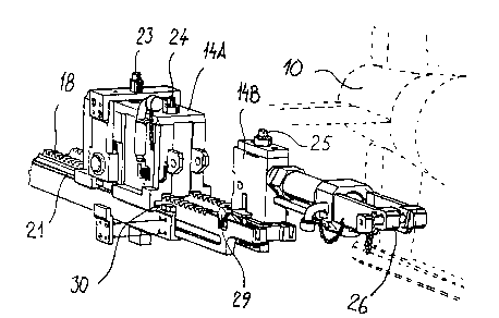
FIG. 3A and 3B are perspective views of the device
according to the invention in a starting position and
FIG. 4A and 4B are perspective views of a part of the
device according to the invention.
FIG. 1 shows the arrangement in principal of a
torpedo 10 positioned in front of a torpedo tube 11 in a
submarine. Please note that the torpedo in FIG. 1 for
drafting reasons is cut in two places and in reality is
longer in relation to the person appearing in FIG. 1.
During operation of the submarine said torpedo is fixed, by
means of bands 12,13, in a guideway 15 shaped as a chute.
The distance between said chute and said torpedo tube is
far smaller than the length of said torpedo. A so called
loading means 14 is releasably mounted in the rear part of
said torpedo. Said loading means comprises a loading means
head 14A and a loading means holder 14B, which is attached
to said torpedo. The forward movement of said loading means
in said chute is described in more detail below with
reference to FIG. 3 and 4, the chute being shown in FIG. l.
~rom FIG. 2 it is more clear that a carrier 16 in form of a
chain runs in said chute. Said chain is driven by a conven-
tional motor 19 through a gear box.
From FIG. 2 it is clear that said chute is formed
with two skid rails 29A and B, on which said torpedo slidas
during its movement towards said torpedo tube. Between said
skid rails is arranged an elongated three part guide bar 21
having a U-shaped cross section. Inside, on the base of
said guide bar r-ms one part of said chain 16. The return
part of said chain runs on the underside of said guide bar
21. A twin rack 18 i5 slidably disposed on two ledges 22

WO91/0490~ PCT/SE90/00615
2 ~ ~S ~ ~
extending inwardly from the vertical stems of said guide
bar. The teeth of said twin rack l8 are arranged approxi-
mately in level with the upperside of the stems of said
guide bar.
The outlook of said loading means 14 is shown on FIG.
3A and FIG. 3B. By means of three vertically disposed
adjusting screws 23,24 and 25 different parts of said
loading means are displaceably downwardly against and
upwardly from said chain 16, said twin rack l8 (see FIG.
4B) and said guide bar 21, respectively. Said loading means
holder 14B comprises also a coupling 26, which is
releasably connected to said torpedo (see FIG. 4A).
~ith reference to FIG. 3A and 3B the function of said
loading means 14 will be described. In the starting
position said adjusting screw 23 is screwed up, whereby a
larger gear wheel 27 carried in said loading means is
lifted out of engagement with said chain 16, which in this
position is standing still. Also the adiustment screw 2S is
screwed up whereby ratches 29 (see FIG. 4A) pivotally
carried in sai~ twin rack under spring biasing are lowered
down in recesses 30 in the upper part of the stems of said
guide bar 21, thereby locking said twin rack 18 in relation
to said guide bar 21. The adjustment screw 24 is screwed
down, whereby a driving rod 31 (see also FIG. 4B) engages
said chain 16. In this positi~n said chain 16 is moved by
said driving motor l9, the upper part of said chain being
moved towards said to~pedo tube bringing by means of said
driving rod 31 also the complete loading means and the
torpedo. When the loading means reaches the end of said
guide bar 21 the mo~ement of said chain is stopped and said
adjustment screws are readjusted as stated below.
The adjustment screw 23 is now screwed down and said
larger gear wheel 27 engages said chain while at the same
time two smaller gear wheels 28 arranged on the same shaft

W091~04905 PCT/SE90/00615
2~ ;8
as said gear wheel 27 engages said twin rack 18. Also said
adjustment screw is screwed down to release said twin rack
18 from said guide bar 21 by said ratches 29 being pressed
downwardly and pivoted out of position in said recesses 30.
At the same time said loading means holder 14B is fixed in
said twin racX. Said adjustment screw 24 is screwed up and
releases said driving rod 31 from engaging said chain. The
two main parts of said-loading means, i.e. the loading
means head 14A and the loading means holder 14B are
releasably connected. FIG. 3 shows an embodiment according
to which said main parts are connected by means of an
external locking rod 32, but in another embodiment said
adjustment screw 25 acts on an internal locking device, not
shown here, which releases said main parts from each other.
When the driving motor again is brought to drive said uppex
part of said chain towards said torpedo tube the larger
gear wheel 27 and th~ smaller gear wheels 28 will rotate.
Thereby said twin rack 18 is given a forward movement which
applies also to said loading means holder 14B mounted
thereon.
In the position shown in FIG. 4 said twin rack has
been moved a short distance out of said guide bar 21. The
movement is then maintained until said torpedo has reached
the desired position in s~id torpedo tube.

Dessin représentatif
Une figure unique qui représente un dessin illustrant l'invention.
États administratifs

2024-08-01 : Dans le cadre de la transition vers les Brevets de nouvelle génération (BNG), la base de données sur les brevets canadiens (BDBC) contient désormais un Historique d'événement plus détaillé, qui reproduit le Journal des événements de notre nouvelle solution interne.

Veuillez noter que les événements débutant par « Inactive : » se réfèrent à des événements qui ne sont plus utilisés dans notre nouvelle solution interne.

Pour une meilleure compréhension de l'état de la demande ou brevet qui figure sur cette page, la rubrique Mise en garde , et les descriptions de Brevet , Historique d'événement , Taxes périodiques et Historique des paiements devraient être consultées.

Historique d'événement

Description Date
Inactive : CIB de MCD 2006-03-11
Le délai pour l'annulation est expiré 1994-03-26
Demande non rétablie avant l'échéance 1994-03-26
Réputée abandonnée - omission de répondre à un avis sur les taxes pour le maintien en état 1993-09-27
Inactive : Demande ad hoc documentée 1993-09-27
Demande publiée (accessible au public) 1991-03-27

Historique d'abandonnement

Date d'abandonnement Raison Date de rétablissement
1993-09-27
Titulaires au dossier

Les titulaires actuels et antérieures au dossier sont affichés en ordre alphabétique.

Titulaires actuels au dossier
KOCKUMS AB
Titulaires antérieures au dossier
IVAN BOSTROM
Les propriétaires antérieurs qui ne figurent pas dans la liste des « Propriétaires au dossier » apparaîtront dans d'autres documents au dossier.
Documents

Pour visionner les fichiers sélectionnés, entrer le code reCAPTCHA :


Pour visualiser une image, cliquer sur un lien dans la colonne description du document. Pour télécharger l'image (les images), cliquer l'une ou plusieurs cases à cocher dans la première colonne et ensuite cliquer sur le bouton "Télécharger sélection en format PDF (archive Zip)" ou le bouton "Télécharger sélection (en un fichier PDF fusionné)".

Liste des documents de brevet publiés et non publiés sur la BDBC .

Si vous avez des difficultés à accéder au contenu, veuillez communiquer avec le Centre de services à la clientèle au 1-866-997-1936, ou envoyer un courriel au Centre de service à la clientèle de l'OPIC.


Description du
Document 
Date
(aaaa-mm-jj) 
Nombre de pages   Taille de l'image (Ko) 
Abrégé 1991-03-26 1 47
Dessins 1991-03-26 4 113
Revendications 1991-03-26 2 68
Abrégé 1991-03-26 1 59
Description 1991-03-26 4 164
Dessin représentatif 1998-12-22 1 16
Taxes 1992-09-07 1 31
Rapport d'examen préliminaire international 1992-03-24 13 320
Courtoisie - Lettre du bureau 1992-10-29 1 46