Note : Les descriptions sont présentées dans la langue officielle dans laquelle elles ont été soumises.
~ 2066949
1. Field of the Invention
The present invention relates to air supplying -
apparatus which condition air in terms of cleanliness,
temperature and humidity and which supply the controlled
05 (conditioned) air into a room.
2. Description of Related Art
Air supplying apparatus are used for the purpose of
supplying clean air, or clean air with controlled
temperature and humidity into rooms which are in need of
such conditioned air. Rooms requiring conditioned air
include, e.g., rooms in which .semiconductors, electronic
devices~and precision devices are produced, rooms in which
pharmaceutical products or foodstuffs are produced,
hospital operating ~roomis, and iso forth. (Such rooms will
15~ be~generally referred to as "cIean rooms", hereafter).
: : ~a ~ ~
An air cleaning system, which is one~type of such air
~upplying apparatus, ha9 an air recirculating blower and a
filter whlch are di~po~ed out~ide a room, and air isupply
pipes installed in the ceiling wall and side walls of the
roomO The supply pipes have outlet openings which open in
the surfaces of such walls, so that filtered air blown by
the hlower is supplied into the room through the outlet
openings .
:,
::
.
; ,
; 2
: ; :
206~9
This type of system can supply air over a wide area in
the room at a sufficiently large flow rate, but requires
much cost and labor to install the air supply pipes, which
must be embedded in the ceiling and side walls of the room
and which open through the inner surfaces of the ceiling
and side walls. In particular, introduction of this system
to a room of an existing building requires a long
construction period, as well as a huge cost.
An air cleaning unit has been known in which an air
recirculating blower and a filter are assembled together in
a casing which is provided at its top and bottom ends with
a clean air discharge opening and a room air suction
opening respectively. It is possible to clean the air in a
room with such an air cleaning unit. This unit, however,
lS can supply clean air only to limited portions of the room,
and is unable to recirculate air at a sufficientl~ large
rate to clean an entire room. With such air cleaning
units, therefore, it is not possible to clean the air in a
room to a desired extent.
~ In order to overcome these problems, Japanese Laid-Open
Patent No. 59-44538 proposes an improved air cleaning unit
. . . . .
which employs a columnar structure equipped with an air
suction opening and an air recirculating blower. A duct of
a specific cross-sectional shape is provided on the upper
side of this columnar structure so as to extend along the
.~:
2~6~9
lower surface of a ceiling. Air outlets are provided in
the duct. A plurality of such air cleaning units are used
in a room having a large volume. In this known air
cleaning unit, however, no ~pecific consideration has been `~
given to the pattern of distribution of the air discharged
from the air outlets. Consequently, the cleaned air cannot
~ ~ be supplied uniformly over the entire area of the room,
;~ which undesirably results in local concentrations or
thinning of the controlled air, causing the cleanliness of
the air in the room to be locally degraded, or the
temperature and/or humidity to be deviated from the target
level at local regions in the room.
This type of air cleaning unit also poses a problem in
tha~ a considerably high level of noise is generated during
its operation from, for example, the motor and blades of
the blower. ~ Consequently, noise limits are often exceeded
in rooms where silence must be kept, e.g., ho~pital
operating rooms. This problem is serious particularly when
a plurality oE ~uch air cleanlng units are used to cover a
large space in a large room having a large internal volume.
OB3ECTS AND SUMMARY OF THE IMVENTIOM
~ ccordingly, an object of the present invention is to
provide an air supplying apparatus which is capable of
~ uniformly discharging air~from its air outlets at a reduced
; 4
20~6~9
, ~ ,
level of noise as compared with known air cleaning systems
or units.
It is another object of the present invention to
provide an air supplying apparatus which is capable of
05 uniformly conditioning the air in a room, without any local
,:
concentrations of unconditioned air resulting.
To achieve the foregoing and other objects, and to
overcome the shortcomings discussed above, according to the
present invention there is provided an air supplying
apparatu~ comprising: an air control unit for discharging
air conditioned to a desired state; and an air discharging
duct connected to an air outlet of the air control unit so
as to receive the conditioned air from the air control unit
through an openlng which opens in a direction different
: 15 ~ rom the direction~of flow of air through the air control
: ~ uni.t, the air discharge duct being formed from at least one
~ perforated sheet having a multiplicity of air outlet
:
apertures. .
BRIEF DESCRIPTION OF THE DRAWINGS
2~ The invention will be described in detail with
reerence to the following drawings in which like reference
numerals refer to like elements, and wherein: :
Flg. 1 i~ a schematic illustration of an air supplying `~
apparatus installed in a clean room;
.
'
.
2~6~9
Fig. 2A is a cross-sectional side elevational view of
an air outlet duct;
Fig. 2B is a cross-sectional view taken along the line
A-A of Fig. 2A;
05 ~'ig. 3A is a side elevational view of a flow adjusting
device;
Fig. 3B is an overhead view of the flow adjusting
device;
Fig. 4 is a graph showing air blow-out velocity along
the air outlet duct in relation to the distance from the
inlet of the air outlet duct;
Fig. 5 is a perspective view of an air supplying
apRaratus having a joint duct;
Fig. 6 is a cross-sectional side elevational view of an
air supplying apparatus having a joint duct with an
internal projection serving as a baffle member;
Fig. 7 is a graph showing the sound pressure levels of
various air supplying apparatus; and
Fig. 8 is a perspective view of another embodiment o~
the air supplying apparatus in accordance with the present
invention.
DETAILED DESCRIPTION OF THE PREFERRED EMBOVIMENTS
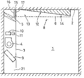
Referring to Fig. l~which is a schematic illustration
o an air supplying apparatus according to one embodiment
of the pre~ent invention installed in a clean room l, the
9 ~ 9
.
air supplying apparatus include an air control unit 3, and
an air outlet duct 8 which is connected to extend in a
~ direction different from the direction of the flow of air
through the alr control unit 3 and which distributes the
o5 cleaned air into the room 1. That is, in Fig. 1, air flows
in the vertical direction through air control unit 3, while
air flows in the horizontal di.rection through air outlet
duct 8.
The air control unit 3 includes an air inlet unit 21, a
blower 4, a high-efficiency particulate air filter 5
capable of removing dust and other contaminants from the
air, a cooler 9 for cooling the air, a heater 10 for
heating the air and a humidifier 11 for controlling the
humidity of the air~. The various components can be
operated with blower 4 individually or in combination.
The air outlet duct 8 connected to the air control unit
3 is adapted to deflect the air flowing through the air
control unit 3, sUch that the air flows, for example, in
parallel with the ceiling 2 of the room. The portions of
the air outlet duct 8 other than the portion contacting the
ceiling 2 are made of one or more perforated sheets 6,
e.g., one or more punched metal shects, having a
multiplicity of pores serving as air outlet apertures 7.
Preferably the air outlet apparatus 7 are evenly
~5 distributed overtle entire surface of perforated sheet 6.
.
: : ;
2~9~9
, ~ .
The air outlet duct 8 has a cross-sectional shape
similar to that of a ship's hull as shown in Fig. 2B and is
elongated so aa to extend along the ceiling as shown in
Fig. 2A. The cross-sectionaI shape of air outlet duct 8
.
oS shown in Fig. 2B~is only illustrative; the air outlet duct
can have any other suitable cross-secti~onal shape such as,
for example, a rectangular, semi-ciroular or inverse ;
trapezoidal form~, provided that the duct can uniformly
aupply air over aa wide an ~area as possible in the room.
As will be seen from Fi~. 2A, the cross-sectional area
of the space inside air outlet duct 8, ~ which is available
as the air passage, is progressively decreased from the
upstream end region 13 (inlet) towards the downstream end
region 14 as viewed in the direction of the flow of air.
lS As one meana for progressively decreasing the cross-
seotional area of the air passage, the cross-sectional area
~of the~air outlet duct is progressively decreased from
upstream end 13 towards downstream end 14 linearly or in a
~tepped manner. Alternatively, a flow passage adjusting
zo member 12 can be in~talled in the air outlet duct 50 as to
progressively dearease the cross-sectional area o ~he
passage, as shown in Fig. 1 and 2A.
~ The total head of the air in duct 8, which is the sum
of the dynamic pre8sure V2/2 and the static preasure, is
25 ~ aubstantially equal over the entire region of the duct, and
. " ' , . ',. ',. . , :., ,' , ',; j ,, , ;i , ." ~ .;,
2 ~
the rate of discharge of the air depends mainly on the
static pressure in the duct. This means that a uniform
distribution of air discharge rate over the entire area of
the duct is obtainable by developing a substantially equal
flow velocity over the entire length of duct 8. Assuming
that the cross-sectional area of the air flow passage is
uniform (constant) over the entire length of duct 8, the
static pressure is lower at the upstream side 13 where the
~flow velocity is large due to large air flow rate as
compared with the downstream portion 14 where the flow
velocity is small due to small air flow rate. Conversely,
in the downstream portion 14 of the duct, the static
pressure i8 increased due to small air flow rate as
compared with the upstream portion 13. Therefore, when the
cross-sectional area of the air passage in the duct is
:
constant over the entire length of the duct, air is
discharged at a greater rate in the downstream portion 14
than in the upstream portion 13. In the illustrated
embodiment, however, this problem is obviated because t~n~
the cross-sectional area of the flow pas~age ig
progre~isively decreased towards the downstream end of the
duct by the deslgn of the duct or by the provision of the
flow pas~age adjusting member 12 in the duct. Namely, in
the illustrated embodimentj a substantially equal flow
velocity v of air i8 obtained both at the upstream portion
:
:'
"~ "; " ,~ "" ~
2 ~ 9
13 and the downstream portion 14, so that a substantially
uniform static pressure and, hence, a substantially uniform
.
distribution of air discharge rate can be obtained over the `-
entire length of duct 8.
Os In the illustrated embodiment, the distance ~ of the
clearance between the perforated plate 6 forming the duct 8
and the opposing surface of the flow passage adjusting
member 12 is maintained substantially constant across each
cross-sectional portion of duct 8, so that a substantially
equal air discharge rate can be obtained in all directions
at each cross~section of duct 8. This arrangement, in
combination with the progressive reduction in the cross-
sectional area of the air passage mentioned above,
contxibutes to the realization of a uniform distribution of
the controlled air throughout the clean room 1.
Fig. 4 iS a diagram showing the distribution of
velocity of the air discharged from duct 8 in relat~on to
the distance from the duct inlet, i.e., the upstream end 13
of duct 8. Curve A shows the flow velocity distribution as
obtained when the cross-sectional area of the flow passage
in the duct is constant over the entire length of duct 8,
while curve B shows the flow velocity as observed when the
cross-sectional area o~ the flow passage is progressively
decreased towards the downstream end 14 of duct 8. It will
25 be ~een that the progressive reduction of the cross- ~`
;, . . ; , ~ , :, : , ,. ............ " : . .
' ` ' ` . , ~, ., ' ' ' ' i' ` '; ' ' ' ' ' `, ~' 1,~ .': ' '" ' ' .` ' ' . " ' '
:`~ 2 ~
sectional area of the f].ow passage greatly contributes to
the realization of uniform distribution of air discharge
rates.
A test was conducted in which the time required for the
05 air in the clean room 1 of Fig. 1 to be cleaned to a
cleanli~ness degree of class 100 (Federal Standard 2090) was
measured for both a duct having a constant cross-sectional
area of the flow passage, and a duct having a progressively
decreasing cross-sectional area of flow passage. The time
required for cleaning to class 100 was measured to be 30
minutes when the~duct having a constant cross-sectional
area flow passage was used, and 10 minutes when the duct
having a progressively decreasing cross-sectional area flow
passage was used. It i9 thus possible to shorten the time
re~uired for cleaning the air in a room, by evenly
:
~dis~tributing the~cleaned air throughout the space in the
; room.
description will~now be given of a modification which
employs a flow adjusting deviGe 15 shown in Fig. 1.
20 Fig. 3~ is a schematic side elevational view o~ the
flow adjusting device 15, while Fig. 3B is a schematic
overhead view of~the same.
The ~ow adjusting device 15 is disposed at the air
inlet o~ duct 8 which is installed in the clean room 1
ahown in Fig. 1. The flow adjusting device 15 includes
';'
''` -
1~ ' :
. .
2 ~ 9
vertical blades 16 and horizontal blades 17, both having anair foil cross~section and being movably mounted so as to
enable the direction of the flowing air to be adjusted both
vertically and horizontally. Blades 16 and 17 are
05 supported by respective shafts through friction. The level
of friction is large enough to hold the blades in position
against the pxessure of the flowing aix but is small enough
to permit an easy xotation of the blades on the shafts by
manual orce.
When measurement of the cleaned air distribution in the
clean room shows that there is a local concentration of the
cleaned air in the room, the user can adjust the directions
of blades 16 and 17 80 as to adjust t~e direction of the
air entering duct 8~ thereby minimizing local concentration
of cleaned air in the clean room.
; A certain degree of offset or local concentration can
occur in the flow of air emerging ~rom filter 5 and
entering duct 8. In other words, the flow velocity of air
may not be uniorm in a cross-~ectional plane at the inlet
of duct 8. Therefore, a nonuniform distribution of air
discharge rate may be undesirably created in the inlet or
upstream portion 13 of duat 8, as shown by the curve B in
Flg. 4. ~his problem, however, can be overcome by the
provision of the flow adjusting device 15 which employs two
types of blades 16, 17 for adjusting the flow of air both
12
,.. . . ~- ~ . . . .. . .
:;'' ~. `:, !
2 ~
in the vertical and horizontal directions so as to develop
a substantially uniform distribution of the air flow rate
at the entrance of duct 8. It is therefore possible to ~
obtain a substantially uniform dlstribution of air ~ -
oS discharge rate in the upstream portion 13 of the duct 8~ ;
In Fig. 4, curve C shows the air discharge rate
; distribution as observed when both the flow passage
adjusting member 12 and the flow adjusting device 15 are
`` simultaneously used. It will be seen that a further
uniform air discharge rate distribution is attained by the
combined use of the flow passage adjusting member 12 (flow
passage cross-section adjusting member) and the flow
adjusting device 15 (Elow direction adjusting device). ;
Consequently, the cleaned air can be distributed throughout
the space~in the clean room with a greater degree of
uniformity, thus~offering a remarkable effect of cleaning
air in the clean room.
As will be seen from Figs. 2A and 2B, portions of the
air outlet duct 8 other than the portion contacting celling
2 of the clean room are composed of one or more perforated
sheets 6 (made from, for example, punched metal) each
having a multipllclty of air outlet aperture~ 7. The
diameter, a, of each air outlet aperture is determined in
relation to the thickness, d, of the perforated sheet 6 so
as to meet the condition o d/a ~ 1. This condition
13
:: :
: :
20~6~9
ensures that the flow of the air is stabilized in each
outlet aperture 7 so as to enable the air to be discharged
in the direction of the axis of each aperture (i.e., in
Fig. 1 straight down). If the diameter, a, does not meet
os the above-described condition, i.e., when the condition is
such that d/a <~1, the flow of air exiting from each
aperture inevitably has a flow component directed in the
longitudinal direction of the duct 8. Consequently, the
cleaned air discharged from outlet apertures 7 formed in
the bottom wall of duct 8 are undesirably directed
obliquely downward rather than being directed vertically,
resulting in lack of uniformity in the distribution of the
discharged air.
A descriptlon will now be given of another modification
having a joint duct, with specific reference to Fig. 5.
The air supplyin~ apparatus shown in Fig. S, installed in a
clean room, has an air control unit 3 for discharging air
which has been controlled to a desired degree o
clea~lines~, temperature and humidity, a joint duct 18
which is connected to the outlet end of the air control
unit 3 and an air outlet duct 8 which is connected to the
downstream end of the jOillt duct 18. The ioint duct 18
~an be connected to any desired side of the air control
unit 3, depending on the geometrical form and size of the
room. When the clean room has a large internal volume, it
,
14
2~9~9
'`:'
is possible to use two of these apparatus, such that the
two apparatus are disposed to oppose each other.
The air flowing through the air control unit 3 is
introduced into the joint duct 18, through an opening which
05 opens in a direction different from the direction of flow
of the air through the air control unit 3. The air then
.
enters the air outlet duct 8 through an opening which opens
in a direction different from the direction of flow of air
through the joint duct 18.
10Consequently, the air discharged from the air control
unit 3 is repeatedly deflected as the air passes through
the openings which are directed in different directions.
In addition, the cross-sectional area of the air passage
changes as the air flows from the air control unit 3 into
the joint duct l~ and then into the outlet duct 8.
~.
; Consequentlyl the noise energy propagating through the air
is extinguished as a result of conversion from kinetic
energy into thermal energy. Consequently, the level o
noise is lowered each time the flow o air is de1ectedr
whereby the noise level is lowered in the clean room.
Another embodiment of the present invention will be
de~cribed with reference to Fig. 6.
As is the case of the apparatus shown in Fig. 5, the
~econd embodiment of the air supplying apparatu~ of the
present invention lncludes an air control unit 3, a joint
:.
1~
.
.,~ .. . ..
: 2~g~949
duct 18 connected to the outlet end of air control unit 3
and an air ou-tlet duct 8 connected to the downstream end of
joint duct 18.
A tabular member 19 protrudes from a wall of joint duct
05 18 so as to project into the air passage. Tabular member
19 functions as a baffle plate which deflects air.
Consequently, the air flowing through joint duct 18
experiences changes in the cross-sectional area of the flow
passage, as well as flowing direction, so that the noise
energy propagated through the flow of air is converted into
thermal energy, thus attaining a remarkable reduction in
the noise level within the clean room.
A further reduction in the noise level can be attalned
by lining the walls of the joint duct 18 with a sound
absorbing material 20 which is, in this embodiment, an
aluminum wool mat of about 25 mm thick.
With specific reference to Fig. 7, a description will
now be given of the results of measurements of noise levels
produaed by variou~ types of air 9upplyin~ apparatus. More
speciiaally, Fig. 7 shows the measurements o sound
pressure levels as measured at the center of a room at a
level about 1.2 m above the floor surface, when the blower
motor 4 in the air control unit 3 was operated at a
fre~uency of about 50 Hz. The measurement was conducted
through octave band analysis. The abscissa~represents the
16
. ~ i ' ,; .: ~., ;~ , " ,~ , , , " ~ , , " , , "
... , ; : . . .. . .. .. .
2~949
central frequency (Hz) of the octave band, while the
ordinate axis represents the sound pressure level.
A solid-line curve 22 shows the values measured with a
conventional air supplying apparatus. In thls case, peaks
05 of sound pressure were observed at almost all central
; frequency bands. The maximum sound pressure level was 61dB
(A). The NC value in the 125 Hz band exceeds 60.
A chain-line curve 23 shows the sound pressure levels
as observed with the air supplying apparatus of the
invention incorporating the joint duct 18. A two-dot-and-
dash line 24 shows the sound pxessure levels as observed
when the joint duct 19 is provided with the tabular member
19 serving as a baffle plate. A one-dot-and-dash line
curve 25 indicates the sound pressure levels as observed
;
when the joint duct 18 is e~uipped both with the tabular
`
member 19 and the sound absorbing lining 20. It will be
seen that the noise level in the clean room can be
appreciably reduced by using the air supplying apparatus o
the present invention.
In the known air supplying apparatus, only one air
discharge duct 8 is used for one air control unit 1. This
means thak when a plurality of air discharge ducts are to
be employed, it is necessary to ins~all plural air control
units correspondingly in the clean room. Fig. 8 shows a
modification of the air supplying apparatus in which three
.
17
~,, .. : .. : .... .... ::.:.: ~ ; :.
2~9~ ~
.
ducts 8 are connected to a single air control unit. By
using this air supplying apparatus, it is possible to
reduce the number of alr control units to be installed so
that the installation cost can be remarkably reduced. The
05 reduction in the number of air control units also
appreciably saves cost and time required for maintenance.
Although the modification shown in Fig. 8 has three air
discharge ducts 8 connected to a single air control unit 3,
any desired number of air discharge ducts, e.g., two, four
or more, may be connected to the air control unit 3. The
number of air discharge ducts 8, as well as the directions
t.~ ~ in which these ducts extend, may~ determined in accordance
with the shape of the room.
As will be understood from the foregoing description,
according to the present invention, an air outlet duct is
connected to an air control unit so as to guide the air in
a direction different from the direction of flow of the air
through the air control unit. The cross-sectional area o
the air passage defin0d in the air outlet duct is
progreg8ively reduced towards the down9tream end of the air
outlet duct. In a preferred form o the invention, the
duct i~ formed Erom one or~ more perEorated sheets having a
multiplicity of air outlet apertures, the diameter of which
is controlled in relation to the thickness of the
perforated sheet. In another preferred form, a joint duct
18
~- 2 ~ 4 9
is connected between the air control unit and the air
outlet duct so as to realize a repeated change in the
flowing direction of the cleaned air.
By virtue of these features, the air supplying
05 apparatus of the present invention can create a uniform
distribution of cleaned air throughout a clean room, while
reducing the level of the noise, as well as the cost ;
required for installation.
While this invention has been described in conjunction
with specific embodiments thereof, it is evident that many
alternatives, modifications and variations will be apparent
to those skilled in the art. Accordingly, the preferred
embodiments of the invention as set forth herein are
intended to be illustrative, not limiting. Various changes
15; ma~ be made without departing from the spirit and scope of
the invention as defined in the following claims.
19
.