Sélection de la langue

Search

Sommaire du brevet 2067154 

Énoncé de désistement de responsabilité concernant l'information provenant de tiers

Une partie des informations de ce site Web a été fournie par des sources externes. Le gouvernement du Canada n'assume aucune responsabilité concernant la précision, l'actualité ou la fiabilité des informations fournies par les sources externes. Les utilisateurs qui désirent employer cette information devraient consulter directement la source des informations. Le contenu fourni par les sources externes n'est pas assujetti aux exigences sur les langues officielles, la protection des renseignements personnels et l'accessibilité.

Disponibilité de l'Abrégé et des Revendications

L'apparition de différences dans le texte et l'image des Revendications et de l'Abrégé dépend du moment auquel le document est publié. Les textes des Revendications et de l'Abrégé sont affichés :

  • lorsque la demande peut être examinée par le public;
  • lorsque le brevet est émis (délivrance).
(12) Demande de brevet: (11) CA 2067154
(54) Titre français: DISPOSITIF DE LEVAGE
(54) Titre anglais: LIFTING APPARATUS
Statut: Réputée abandonnée et au-delà du délai pour le rétablissement - en attente de la réponse à l’avis de communication rejetée
Données bibliographiques
(51) Classification internationale des brevets (CIB):
  • B65F 3/02 (2006.01)
  • B65F 3/04 (2006.01)
(72) Inventeurs :
  • GUEST, STEPHEN JOHN (Australie)
(73) Titulaires :
  • STEVELIFT PTY LTD.
(71) Demandeurs :
  • STEVELIFT PTY LTD. (Australie)
(74) Agent: GOWLING WLG (CANADA) LLP
(74) Co-agent:
(45) Délivré:
(86) Date de dépôt PCT: 1990-10-12
(87) Mise à la disponibilité du public: 1991-04-13
Requête d'examen: 1997-10-02
Licence disponible: S.O.
Cédé au domaine public: S.O.
(25) Langue des documents déposés: Anglais

Traité de coopération en matière de brevets (PCT): Oui
(86) Numéro de la demande PCT: PCT/AU1990/000488
(87) Numéro de publication internationale PCT: WO 1991005721
(85) Entrée nationale: 1992-04-10

(30) Données de priorité de la demande:
Numéro de la demande Pays / territoire Date
PJ6835 (Australie) 1989-10-12

Abrégés

Abrégé anglais

2067154 9105721 PCTABS00005
A lifting apparatus (10) to be attached to the side of a garbage
collection truck. The apparatus comprises a series of linkages
(12, 14, 15, 17, 18) mounted to a mounting member (11) attached to
the vehicle. A plurality of suction cups (20) is provided on a
garbage bin securing member (18). A vacuum supply to the suction
cups is actuated by means of a trip switch (26) mounted adjacent to
the suction cups. The trip switch (26) is activated as it abuts
the side of a garbage bin. The vacuum supply is disconnected as
the bin securing member (18) returns past a predetermined
position. In a preferred embodiment, the securing member (18) is mounted
on lateral shift rails (27) to allow for positional adjustment of
the bin securing member (18) relative to the bin. The apparatus
is adapted to raise a garbage bin from a position generally
adjacent the truck to a raised and inverted position adjacent to an
entry shute of a garbage compactor of the garbage truck.

Revendications

Note : Les revendications sont présentées dans la langue officielle dans laquelle elles ont été soumises.


WO 91/05721 PCT/AU90/00488
- 5 -
The claims defining the invention are as follows:
1. Apparatus comprising:
lifting means to be attached to a vehicle
object securing means mounted to said lifting means so as to be
lifted thereby
said lifting means being moveable between a retracted position
wherein said object securing means is located adjacent an object to be
lifted and an extended position wherein said object securing means is in a
raised essentially inverted position and
wherein said object securing means comprises suction fastening
means connected to a vacuum supply and a switch means adapted to be
activated or deactivated at a predetermined position during movement of
said lifting means so as to supply or disconnect said vacuum.
2. Apparatus according to claim 1 wherein said lifting means
comprises a mounting member to be attached to a side of said vehicle in a
generally vertical orientation.
3. Apparatus of claim 2 wherein said lifting means comprises a
lifting arm pivotally mounted proximate a top end of said mounting member
the lifting arm being moveable relative to the mounting member between said
retracted and extended positions such that in said retracted position said
lifting arm is generally co-extensive and parallel with the mounting
member.
4. Apparatus as claimed in claim 3 further comprising a first
member pivotally mounted to said mounting member at a position spaced from
a pivotal axis of the lilting arm to the mounting member a second member
pivotally mounted to the lifting arm at a position spaced from the said
axis and a third member pivotally mounted to the object securing means at
a position spaced from a pivotal axis between the bin securing means and
the lifting arm.
5. Apparatus according to claim 4 wherein the lifting arm and the
object securing means are connected in such a way so as to generally define
a parallelogram linkage which maintains a particular orientation of the
object securing means relative to the ground within a predetermined range
of movement of the lifting arm.
6. Apparatus according to claim 1 wherein said suction fastening
means comprises a plurality of suction cups.

WO 91/05721 PCT/AU90/00488
- 6 -
7. Apparatus of claim 6 wherein in said retracted position, the
suction cups face outwards from said vehicle and are aligned essentially
vertically.
8. Apparatus of claim 6 wherein there is attached to each of said
plurality of suction cups an air hose, each connected to a vacuum supply
via an air operated trip switch.
9. Apparatus of claim 8 wherein said trip switch is located in a
position adjacent said suction cups so as to be activated by contact with
said object to be lifted.
10. Apparatus as claimed in claim 6 wherein said object securing
means further comprises at least one shift rail onto which the suction cups
are mounted by way of a face member which is adapted to slide laterally
along said shift rails.

Description

Note : Les descriptions sont présentées dans la langue officielle dans laquelle elles ont été soumises.

~ a ~
V~l_l . . .............. _ . - . ' ...... P~/~,90/~û480
LIFTING APPARATUS `J l
The present invention relates to a garbage bin lifting means for
garbage collection veh1cles.
Present garbage trucks use hydraulically operated securing means to
11ft garbage b7ns. Such secur1ng means compr1se mechanical arms attached to
main l~ft1ng arms which are adapted to grab mobile garbage b1ns such as
rap1d-ra11s otto bins etc. The arms move to a predetermined position
w1th respect to the b~n and when the ma~n 11ft1ng arm 1s ra1sed they
engage a circumferent~al ridge port1On of the b1n.
The b1n 1s 11fted by the ma1n 11fting arms unt11 1t 1s held up-side
down over the entry chute of the garbage bin truck compactor. The bin 1s
prevented from slipping off the arms of the llft1ng means by a retaining
port1On on the securlng means.
These known types of garbage b~n l~ft~ng apparatus are not adapted
for p1ck~ng up both common available 120 lltre and 240 11tre sized b~ns.
That ~s known 11ft1ng apparatus 1s usually only adapted to 11ft one s1ze
of b~n.
Further the cycle t~me for th1s type of l~ft1ng apparatus ~s
relat1vely long slnce the act~on of the arms can be qu1te slow.
It ~s the ob~ect of the present ~nvent~on to overcome or
substantlally amel1Orate the problems and/or d1sadvantages of the prior art.
In one broad form the present 1nvent1On prov~des apparatus compr1s1ng:
11ftlng means to be attached to a veh1cle
ob~ect secur1ng means mounted to sa1d llft1ng means so as to be
11fted thereby
sa1d 11ft1ng means be1ng moveable between a retracted pos~t~on
where~n sa~d ob~ect secur1ng means 1s located ad~acent an ob~ect to be
llfted and an extended poslt1On where1n~sa1d ob~ect securing means 1s 1n a
ra1sed ~essent1ally lnverted pos1t1On and
wherein sald object secur~ng means compr~ses suctlon fasten1ng means
connected to a vacuum supply and sw1tch means adapted to be act1vated or
deact1vated at a predeterm~ned poslt~on during movement of said l~fting
,
means so as to supply or d1sconnect sald vacuum.
A preferred form of the present 1nvent1On w111 now be descr1bed by
way of example w1th reference to the accompany~ng draw1ngs where~n:
: ~ :
:
:
,
,
'' ' '
- '
,' ' ,
., .
.

~ V ~0~ ^ PC~/Alj9~ 'Yi~
20~7~54 2-
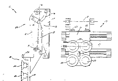
Figure l is a s1de elevat10nal v~ew of the lifting apparatus of the
present 1nvention 1n a folded conf19urat10n
F~gure 2 is a side elevational view of the apparatus of F~gure l 1n a
mid-way position of the 11ft1ng means
F~gure 3 1s a s1de elevational view of the apparatus of Figure l in a
fully ra1sed posit1c~n
Figure 4 1s a s1de elevat10nal v1ew of an alternat1ve embodiment of
the 11ft1ng apparatus of the present 1nvent10n
F19ure 5 1s a front elevat10nal v1ew of the apparatus of Figure 4 and
F~gure 6 is a plan v1ew of the apparatus of F~gures 4 and 5.
In the accompany1ng drawings there is schemat1cally dep~cted a
11ft1ng apparatus lO to be mounted to a garbage truck (not shown) hav1ng a
garbage compactor. Preferably the 11ft1ng apparatus lO is used 1n
conjunct10n w1th a garbage truck adapted for control by a s1ngle operator.
The 11ft1ng apparatus 10 compr1ses a 11ft1ng mechan1sm 25 wh~ch
compr1ses a mount1ng member 11 to be attached to a s1de of the truck 1n a
generally vert1cal pos1t10n ad~acent to the entry chute of the compactor.
Plvotally mounted to the mount1ng member ll prox1mate 1ts top end 1s
the llft1ng arm 12 wh1ch 1s movable relat1ve to the member ll between a
retracted pos~t10n (see F~gure l) generally coextens1ve and parallel to the
mount1ng member ll and a fully extended pos1t10n ~see F19ure 3). F~gure 2
shows the llft1ng arm 12 1n a m1d-way posltlon.
Plvotally mounted to the other end of the 11ft1ng arm 12 ~s a b1n
secur~ng apparatus 18 wh1ch 1s adapted to releasably reta~n a b1n when the
11ft1ng arm 12 ls be1ng ra1sed and lowered.
A 11nkage arrangement 13 1s also prov1ded so that the b1n wh~ch 1s
be1ng l~fted by the l~ft1ng apparatus lO ~s kept generally upr~ght unt~l 1t
1s over the entry chute of the compactor. Th1s ~s necessary to prevent the
garbage w1th1n the b1n from be1ng d1scharged before arr1v1ng at an
approprlate pos1t10n relat1ve to the truck.
~ The 11nkage arrangement 13 compr1ses a f1rst member 14 p1votally
mounted to the mount1ng member ll at a pos~t~on spaced from the p1votal
ax1s 16 of the 11ft1ng arm 12 to the mount1ng member ll; a second member 15
p1votally mounted to the 11ft1ng arm 12 at a pos1t~on spaced from the axis
16 and a th1rd member 17 p1votally mounted to the b1n secur1ng apparatus
18 at a pos1t10n spaced from the p1votal ax1s l9 between the apparatus 18
and the 11ft1ng arm 12.
::
.. . -, . . . . .
. . . .
:, . . - - . . .
. . . ,
- . . .

:
-
91~D~,~; PC~/A~i9~ ldX
1. ~ tJ ~. J
-- 3 --
The second and third members 15 17 the lifting arm 12 and the binsecurlng apparatus 18 are connected in such a way so as to generally define
a parallelogram llnkage wh~ch ma~ntains a particular orientation of the
secur~ng apparatus 18 relat1ve to the ground withln a certaln range of
movement of the 11ftlng arm 12. After this range of movement of the
llftlng arm 12 ls exceeded the first member 14 causes the apparatus 18 to
p~vot wlth respect to the llftlng arm 12 as lt completes lts rotation about
the mountlng member 11 ~nto the fully ra~sed pos~tion ~see Figure 3).
In addlt~on to b1n llp support blocks 22 wh~ch are adapted to catch
under a perlpheral llp of a bln to be lifted the b7n securlng apparatus 18
comprises two or four for example suction cups 20 whlch are mounted to a
stralght face 21 of the apparatus 18. When the liftlng arm 12 ls ln the
folded posltion the suctlon cups 20 face outwards from the truck and are
allgned generally vertlcally.
Communlcatlng wlth each of the suctlon cups 20 is an a1r hose (not
shown) which are each connected to a vacuum supply vla an a~r operated trlp
~swltch 26.
~ ~ In accordance wlth a further embodlment of the present lnventlon the
bln secur~ng apparatus 18 comprises a number of shlft ra~ls 27. In thls
partlcular embodlment the stralght face 21 ls mounted to the sh1ft ralls
27 by means of 11near bearlngs 28. Such a conflguration allows for lateral
transfer of the suctlon cups 20 to compensate for any lnaccuracy of the
garbage truck ln ~ts parked relatlonshlp to the bln to be llfted. Shlft
cylinder 29 1~s prov1ded as a means by wh kh a shlft1ng force ~s applied to
the bln securlng apparatus 18 so as to be transferred along shlft ra~ls 27.
In use the ll~ftlng~arm 12 ls moved away~from the folded posltlon
whlch~actlvates~;the`alr operated trlp swltch 26 so as to provlde a vacuum
to each of~the~suc~tlon cups 20. In the embodlment depicted the tr~p
swltch~26~actlvates~as~tt~engages~wlth the slde of the bin to bé~llfted.
The~suctlon~ cups 20 are~lnltlally ad~acent the bln. A pro~ectlon 22
also pro~ects from~the face 21 of the apparatus 18 wh~ch ls positloned to
butt up~àga~nst~the~slde face~of the bin wh~le 1t ls adhered to the
apparatus~18.~
The~suctlon caps 20 engage a slde face of the bin and adhere thereto
al~lowl;ng~tne bi~n to~be llfted by further pivotlng motion of the llftlng arm
12~towards~;the~extended posltlon. When the l~fting arm 12 ls ln the fully
extended~positlon the garbage wlth~n the bin ~s emptied lnto the garbage
c~ompactor.
- - , ,
.
.
''- . ' ', ,

- WiJ Y;;~;~/2; . - - - PCr/Aj,Y~ X
73 4
-- 4 --
After the bin has been emptied, the lifting arm 12 is moved back
towards the folded position. ~hen the lifting arm 12 reaches the folded
position, the air operated trip switch 26 closes off the vacuum to the
suction caps 20 thus allowing the bin to be released and placed back onto
the ground.
Typically, the cycle time of the present invention is approximately 3
to 6 seconds from the initial folded position to the bin-empty and back to
rest (folded position).
- : ~
.

Dessin représentatif
Une figure unique qui représente un dessin illustrant l'invention.
États administratifs

2024-08-01 : Dans le cadre de la transition vers les Brevets de nouvelle génération (BNG), la base de données sur les brevets canadiens (BDBC) contient désormais un Historique d'événement plus détaillé, qui reproduit le Journal des événements de notre nouvelle solution interne.

Veuillez noter que les événements débutant par « Inactive : » se réfèrent à des événements qui ne sont plus utilisés dans notre nouvelle solution interne.

Pour une meilleure compréhension de l'état de la demande ou brevet qui figure sur cette page, la rubrique Mise en garde , et les descriptions de Brevet , Historique d'événement , Taxes périodiques et Historique des paiements devraient être consultées.

Historique d'événement

Description Date
Demande non rétablie avant l'échéance 1999-10-12
Le délai pour l'annulation est expiré 1999-10-12
Réputée abandonnée - omission de répondre à un avis sur les taxes pour le maintien en état 1998-10-13
Inactive : Dem. traitée sur TS dès date d'ent. journal 1998-04-03
Inactive : Supprimer l'abandon 1998-04-03
Inactive : Renseign. sur l'état - Complets dès date d'ent. journ. 1998-04-03
Inactive : Acc. réc. RE - Pas de dem. doc. d'antériorité 1998-04-03
Inactive : Abandon.-RE+surtaxe impayées-Corr envoyée 1997-10-14
Toutes les exigences pour l'examen - jugée conforme 1997-10-02
Exigences pour une requête d'examen - jugée conforme 1997-10-02
Demande publiée (accessible au public) 1991-04-13

Historique d'abandonnement

Date d'abandonnement Raison Date de rétablissement
1998-10-13

Taxes périodiques

Le dernier paiement a été reçu le 1997-09-03

Avis : Si le paiement en totalité n'a pas été reçu au plus tard à la date indiquée, une taxe supplémentaire peut être imposée, soit une des taxes suivantes :

  • taxe de rétablissement ;
  • taxe pour paiement en souffrance ; ou
  • taxe additionnelle pour le renversement d'une péremption réputée.

Veuillez vous référer à la page web des taxes sur les brevets de l'OPIC pour voir tous les montants actuels des taxes.

Historique des taxes

Type de taxes Anniversaire Échéance Date payée
TM (demande, 7e anniv.) - petite 07 1997-10-14 1997-09-03
Requête d'examen - petite 1997-10-02
Titulaires au dossier

Les titulaires actuels et antérieures au dossier sont affichés en ordre alphabétique.

Titulaires actuels au dossier
STEVELIFT PTY LTD.
Titulaires antérieures au dossier
STEPHEN JOHN GUEST
Les propriétaires antérieurs qui ne figurent pas dans la liste des « Propriétaires au dossier » apparaîtront dans d'autres documents au dossier.
Documents

Pour visionner les fichiers sélectionnés, entrer le code reCAPTCHA :


Pour visualiser une image, cliquer sur un lien dans la colonne description du document. Pour télécharger l'image (les images), cliquer l'une ou plusieurs cases à cocher dans la première colonne et ensuite cliquer sur le bouton "Télécharger sélection en format PDF (archive Zip)" ou le bouton "Télécharger sélection (en un fichier PDF fusionné)".

Liste des documents de brevet publiés et non publiés sur la BDBC .

Si vous avez des difficultés à accéder au contenu, veuillez communiquer avec le Centre de services à la clientèle au 1-866-997-1936, ou envoyer un courriel au Centre de service à la clientèle de l'OPIC.


Description du
Document 
Date
(aaaa-mm-jj) 
Nombre de pages   Taille de l'image (Ko) 
Abrégé 1995-08-08 1 82
Page couverture 1994-03-05 1 12
Revendications 1994-03-05 2 57
Description 1994-03-05 4 165
Dessins 1994-03-05 5 74
Dessin représentatif 1999-01-04 1 14
Rappel - requête d'examen 1997-06-12 1 122
Accusé de réception de la requête d'examen 1998-04-03 1 173
Courtoisie - Lettre d'abandon (taxe de maintien en état) 1998-11-10 1 184
PCT 1992-04-10 10 305
Taxes 1997-09-03 1 34
Taxes 1995-10-12 1 40
Taxes 1996-10-10 1 34
Taxes 1994-10-12 1 37
Taxes 1993-10-12 1 38
Taxes 1992-10-13 1 30
Courtoisie - Lettre du bureau 1998-04-03 1 12