Sélection de la langue

Search

Sommaire du brevet 2068304 

Énoncé de désistement de responsabilité concernant l'information provenant de tiers

Une partie des informations de ce site Web a été fournie par des sources externes. Le gouvernement du Canada n'assume aucune responsabilité concernant la précision, l'actualité ou la fiabilité des informations fournies par les sources externes. Les utilisateurs qui désirent employer cette information devraient consulter directement la source des informations. Le contenu fourni par les sources externes n'est pas assujetti aux exigences sur les langues officielles, la protection des renseignements personnels et l'accessibilité.

Disponibilité de l'Abrégé et des Revendications

L'apparition de différences dans le texte et l'image des Revendications et de l'Abrégé dépend du moment auquel le document est publié. Les textes des Revendications et de l'Abrégé sont affichés :

  • lorsque la demande peut être examinée par le public;
  • lorsque le brevet est émis (délivrance).
(12) Demande de brevet: (11) CA 2068304
(54) Titre français: RALLONGE APPUIE-TETE
(54) Titre anglais: HEAD REST EXTENSION
Statut: Réputée abandonnée et au-delà du délai pour le rétablissement - en attente de la réponse à l’avis de communication rejetée
Données bibliographiques
(51) Classification internationale des brevets (CIB):
  • B60N 02/865 (2018.01)
  • A47C 07/38 (2006.01)
(72) Inventeurs :
  • CASSESE, DANIEL S. (Etats-Unis d'Amérique)
  • SPECTOR, GEORGE (Etats-Unis d'Amérique)
  • SPECTOR, GEORGE (Etats-Unis d'Amérique)
  • CASSESE, DANIEL S. (Etats-Unis d'Amérique)
(73) Titulaires :
  • DANIEL S. CASSESE
  • GEORGE SPECTOR
  • GEORGE SPECTOR
  • DANIEL S. CASSESE
(71) Demandeurs :
(74) Agent:
(74) Co-agent:
(45) Délivré:
(22) Date de dépôt: 1992-05-08
(41) Mise à la disponibilité du public: 1993-11-09
Requête d'examen: 1992-10-16
Licence disponible: S.O.
Cédé au domaine public: S.O.
(25) Langue des documents déposés: Anglais

Traité de coopération en matière de brevets (PCT): Non

(30) Données de priorité de la demande: S.O.

Abrégés

Abrégé anglais


ABSTRACT OF THE DISCLOSURE
A headrest extension is provided for a seat of a type
having an existing built-in headrest supported by a stanchion
extending upwardly from the top of a seat back, of the seat.
The headrest extension consists of a cushion having a body of
relatively soft material and a mechanism for attaching the
cushion to the existing built-in headrest so that when a
person sits in the seat the head of the person can rest
comfortably against the cushion.
-12-

Revendications

Note : Les revendications sont présentées dans la langue officielle dans laquelle elles ont été soumises.


CLAIMS
What is claimed is:
1. A headrest extension for a seat of the type having
an existing built-in headrest supported by a stanchion
extending upwardly from the top of a seat back, of the seat,
said headrest extension comprising:
a) a cushion having a body of relatively soft material;
and
b) means for attaching said cushion to the existing
built-in headrest so that when a person sits in the seat the
head of the person can rest comfortably against said cushion.
2. A headrest extension as recited in Claim 1, wherein
said attaching means includes:
a) a pair of belts, each extending from an opposite
side of said cushion; and
b) hook and loop fabric fastener strips affixed to the
distal ends of said belts so that the distal ends can be
attached to each other when said belts are wrapped around the
existing built-in headrest.
3. A headrest extension as recited in Claim 1, wherein
said attaching means includes a C-shaped spring clamp member
affixed to the rearward end of said cushion which fits onto
the existing built-in headrest.
-8-

4. A headrest extension as recited in Claim 1, wherein
said attaching means includes:
a) the existing built-in headrest having a vertical
slot proximate its forward end thereof; and
b) a flat bar having a hooked end affixed to the top
rearward end of said cushion so that said flat bar will extend
downwardly parallel with the rearward end of said cushion and
fit into the vertical slot in the existing built-in headrest.
5. A headrest extension as recited in Claim 4, further
including:
a) a channel formed in the bottom end of said cushion;
and
b) a shoulder-back contoured extension member having
atop groove attached to and extending downwardly from said
channel to aid in helping a person with back pain to sit more
comfortably in the seat.
6. A headrest extension as recited in Claim 3, further
including:
a) said C-shaped spring clamp member having a threaded
hole therein;
b) a threaded shank engagable within the threaded hole;
c) a pivot joint affixed to the distal end of said
threaded shank;
-9-

d) a wavy circular casing about said cushion, with said
pivot joint connected to the rearward end of said cashing so
that a person can adjust the angle of said cushion via said
pivot joint and can adjust the distance of said cushion from
the existing built-in headrest by rotating said wavy circular
casing thereby causing said threaded shank to move inwardly
and outwardly in the threaded hole.
7. A headrest extension as recited in Claim 1, wherein
said attaching means includes:
a) a first L-shaped member having a first leg affixed
to the rearward end of said cushion and a second leg extending
therefrom;
b) a second L-shaped member having a first leg
telescopically engagable within the first leg of said first
L-shaped member and a second leg extending therefrom; and
c) at least one wing bolt to thread into the first leg
of said first L-shaped member and into the first leg of said
second L-shaped member so as to retain said second L-shaped
member to said first L-shaped member to fit onto the side of
the existing built-in headrest.
-10-

8. A headrest extension as recited in Claim 7, wherein
said attaching means further includes:
a) a pair of flat pins, said first flat pin is mounted
to the side of the second leg of said first L-shaped member
and extends outwardly therefrom, while said second flat pin is
mounted to the side of the second leg of said second L-shaped
member and extends outwardly therefrom; and
b) a pair of belts, said first belt having a slotted
buckle end which fits onto said first flat pin and said second
belt having a slotted buckle end which fits onto said second
flat pin so that the free ends of said belts can be wrapped
around the existing built-in headrest and tied together.
-11-

Description

Note : Les descriptions sont présentées dans la langue officielle dans laquelle elles ont été soumises.

: :
_~Ea__E~ Q~
~~K~ T~ Q~
The instant invention relates generally to motor vehicle
accessories and more specifically it relates to a headrest
extension which pxovides a cushion that i6 attachable to the ;`
existing built-in headrest of a seat.
There are available various conventional accessories
which do not provide the novel improvements of the .invention
herein disclosed.
: .
10 ~yL~O~ ~ '
A primary object of the present invention is to provide
a headrest extension that will overcome the shortcomings of
the prior art devices,
Another object is to provide a headrest extension that
includes a cushion which is attachable to the existing
built~in headrest of a seat so that when a person sits in the
seat the head of the person can rest comfortably against the
:~ cushion. ;~
An additional object is to provide a headrest extension ~ :
that includes a shoulder-back contoured ~xtension member
attachable to and extending downwardly from the bottom of the
:

2 ~
cushion to aid in helping a person with back pain to sit more
comfortably in the seat.
A urther object is to provide a headrest extension that -~
is simple and easy to use.
A still further object is to provide a headrest
extension that is economical in cost to manufacture.
Further objects of the invention will appear as the
description proceeds~
To the accomplishment o the above and related objects,
this invention may be embodied in th~ form illustrated in the
accompanying drawings, attention being called to the fact,
however, that the drawings are illustrative only and that
changes may be made in the specific construction illustrated ~
and described within the scope of the appended claims. ~ ;
-2-

2 ~ 0 ~
~E~~
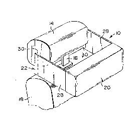
Figure 1 is a side elevational view showing the instant
invention attached to the existing built-in headrest of a seat
occupied by a user.
Figure 2 is a perspective view of the instant invention
partly removed from the headrest.
Figure 3 is a top view taken in direction of arrow 3 in
Figure 1.
Figure 4 is a side eleva~tional view of a second
embodiment of the invention installed on the headrest.
' ~ ~
Figure 4A is a bottom~view with parts broken away taken
in direction of arrow 4A in Figure 4.
Figure 5 is an exploded side elevational view with parts ~ ;
in section and broken away, showing a third embodiment of the
invention.
Figure ~ is a side elevational view with parts in
section and broken away showing a fourth embodiment of the
invention being adjustable to the existing built-in headrest.
.. . . .
-' ~ ,

20~30~ : ~
Figure 7 is a front view taken in direction of arrow 7
in Figure 6, showing the wavy casing about the cushion so that
a person can turn it for adjustment.
Figure 8 is a side elevational view showing a fifth
embodiment of the invention .installed on the headrest.
Figure 8A is a top view taken in direction of arrow 9A
in Figure 8.
Figure 9 is a side elevational view showing a sixth
embodiment of the invention installed on the headrest.
Figure 9A is a top view taken in direction of arrow 9A
in Figure 9. ~ :
.. .
: ~''
-4- ~ ~
. ~ .
:.... ~, :

DET~b~ E~Ç5~ QN-~Q~ Q~ TS
Turning now descriptively to the draw.ings, in which
similar reference characters denote similar elements
throughout the several views, the Figures illustrate a
headrest extension 10 for a seat 12 of the type having an : :
existing built-in headrest 14 supported by a stanchion 16 ;~
extending upwardly from the top of a seat back l~ oE a seat
12. The headrest extension consists of a cushion 20 having a
body of relatively soft materlal and a mechanism 22 for
attaching the cushion 20 to the existing built-in headrest 14
so that when a person 24 sits .in the seat 12, the head 26 of
the person 24 can rest comfortably agalnst the cushion 20.
As bes shown in Figures l, 2 and 3, the attaching ~ ~
mechanism 22 includes a pair of belts 28 with each extending ~ ;
from an opposite side of the cushion 20. Hook and loop fabric ~ : :
fastener strips 30 are affixed to the distal ends of the belts ~:~
28 so that the distal ends can be attached to each other when
the belts 2 are wrapped around the existing built-in headrest
14. ~:
As shown in Figures 4, 6 and 7, the attaching mechanism
22 includes a C-shaped spring clamp member 32 affixed to the
rearward end of the cushion 20, which fits onto the existing ~ :
built-in headrest 14.
Figure 5 shows the attaching mechanism 22 including the
existing built-in headrest 14 having a vertical slot 34
proximate its forward end thereof and a flat bar 36 having a
5-

2~6830A
hooked end 38 affixed to the top rearward end of the cushion
20. The flat bar 36 will extend downwardly parallel with the
rearward end of the cushion 20 and Eit into the vertical slot
34 in the existing built-in headrest 14. A channel 40 may be
formed in the bottom end of the cushion 20. A shoulder-back
contoured extension member 42 has a top groove 44 which can be
attach~d to and extend downwardly from the channel 40 to aid
in helping a person 24 with back pain to sit more comfortably
in the seat 12.
A headrest extension 10, in Figures 6 and 7, further
includes the C-shaped spring clamp member 32 having a threaded
hole 46 therein. A threaded shank 48 is engagable within the
threaded hole 46, while a plVOt joint 50 i9 affixed to the
distal end of the threaded shank 48. A wavy circular:casing
52 is about the cushion 20, with the pivot joint:50 connected
to the rearward end of the cashing 52. A person 24 can adjust :~
the angle of the cushion 20 via the pivot joint 50 and can
adjust the distance of the cushion 20 from the existing
built-in headrest 14 by rotating the wavy circular casing 52,
there~y causing the threaded shank 4R to move inwardly and
outwardly in the threaded hole 46.
In Figures 8 and 8A the attaching mechanism 22 includes ~
a first L-shaped member 54, having a first leg 56 aEfixed to ~ ::
the rearward end of the cushion 20 and a second leg 58
extendiny therefrom. A second L-~haped member 60 has a first
leg 62~te1escopically engagable within the first leg 56 of the
first L-shaped member 54 and a second ley 64 extending
-6-
- . - . ~. .- : . :

~0~3~ ;
therefrom. ~t least one wing bolt 66 is threaded into the
first leg 56 of the first L-shaped member 54 and into the ~-
first leg 62 of the second L-shaped member 60 so as to retain
the second L-shaped member 60 to the first L-shaped member 54
to fit onto the sides of the existing buil~in headrest 14.
Figures 9 and 9A show the attaching mechanism 22 further
including a pair of flat pins 68 and 70. The Eirst flat pin
68 is mounted to the side of the second leg 58 of the Eirst
L-shaped member 54 and extends outwardly therefrom. The
second flat pin 70 is mounted to the side of the second leg 64 ;~
of the second L-shaped member 60 and extends outwardly
thererom. A pair of belts 72 and 74 are provided. The fixst
belt 72 has a slotted buckle end 76 which fits onto the first
flat pin 68~ The second belt 74 has a slotted buckle end 78 ~
which fits onto the second flat pin 70 so that the free ends ~ ;
of the belts 7~ and 74 can be wrapped around the existing
built-in headrest 14 and tied together at 80.
While certain novel features of this invention have been
shown and described and are pointed out in the annexed claims,
it wi11 be understood that varlous omissions, substitutions
and changes in the forms and details of the device illustra-ted
and in its operation can be made by those skilled in the art
without departing from the spirit of the invention.
:` :
~. .
-7-

Dessin représentatif
Une figure unique qui représente un dessin illustrant l'invention.
États administratifs

2024-08-01 : Dans le cadre de la transition vers les Brevets de nouvelle génération (BNG), la base de données sur les brevets canadiens (BDBC) contient désormais un Historique d'événement plus détaillé, qui reproduit le Journal des événements de notre nouvelle solution interne.

Veuillez noter que les événements débutant par « Inactive : » se réfèrent à des événements qui ne sont plus utilisés dans notre nouvelle solution interne.

Pour une meilleure compréhension de l'état de la demande ou brevet qui figure sur cette page, la rubrique Mise en garde , et les descriptions de Brevet , Historique d'événement , Taxes périodiques et Historique des paiements devraient être consultées.

Historique d'événement

Description Date
Inactive : CIB désactivée 2019-01-19
Inactive : CIB en 1re position 2018-04-24
Inactive : CIB attribuée 2018-04-24
Inactive : CIB expirée 2018-01-01
Le délai pour l'annulation est expiré 1995-11-08
Demande non rétablie avant l'échéance 1995-11-08
Inactive : Demande ad hoc documentée 1995-05-08
Réputée abandonnée - omission de répondre à un avis sur les taxes pour le maintien en état 1995-05-08
Demande publiée (accessible au public) 1993-11-09
Exigences pour une requête d'examen - jugée conforme 1992-10-16
Toutes les exigences pour l'examen - jugée conforme 1992-10-16

Historique d'abandonnement

Date d'abandonnement Raison Date de rétablissement
1995-05-08
Titulaires au dossier

Les titulaires actuels et antérieures au dossier sont affichés en ordre alphabétique.

Titulaires actuels au dossier
DANIEL S. CASSESE
GEORGE SPECTOR
GEORGE SPECTOR
DANIEL S. CASSESE
Titulaires antérieures au dossier
S.O.
Les propriétaires antérieurs qui ne figurent pas dans la liste des « Propriétaires au dossier » apparaîtront dans d'autres documents au dossier.
Documents

Pour visionner les fichiers sélectionnés, entrer le code reCAPTCHA :


Pour visualiser une image, cliquer sur un lien dans la colonne description du document. Pour télécharger l'image (les images), cliquer l'une ou plusieurs cases à cocher dans la première colonne et ensuite cliquer sur le bouton "Télécharger sélection en format PDF (archive Zip)" ou le bouton "Télécharger sélection (en un fichier PDF fusionné)".

Liste des documents de brevet publiés et non publiés sur la BDBC .

Si vous avez des difficultés à accéder au contenu, veuillez communiquer avec le Centre de services à la clientèle au 1-866-997-1936, ou envoyer un courriel au Centre de service à la clientèle de l'OPIC.


Description du
Document 
Date
(aaaa-mm-jj) 
Nombre de pages   Taille de l'image (Ko) 
Dessins 1993-11-08 2 63
Revendications 1993-11-08 4 113
Abrégé 1993-11-08 1 17
Description 1993-11-08 7 228
Dessin représentatif 1999-03-08 1 8
Taxes 1993-05-26 1 47
Demande de l'examinateur 1993-01-12 2 41
Correspondance de la poursuite 1992-10-15 1 26