Note : Les descriptions sont présentées dans la langue officielle dans laquelle elles ont été soumises.
WO 91/l~Yi46'1 PCl/VS!~)/069g2
.
1 ~
2 ~ 5 ~
SA~3?LE HANI)LING SY5TEM FOR AN
OPI':CCAL MONITORING SYSTEM
CROSS REEli'RENOE TO REIATED APPLICATION'.
This application is related to t:he followiny concur-
5 rently filed and copending U.S. Patent Applications, which ~:
are owned by the Assignee of the pres~ent Application, and
the disclosures of which are incorporated herein by
reference:
(1) Serial No. 07/443,952, to Swope et al
entitled "Multichannel, Optical Monit.oring Systems";
(2) Serial No. 07/443,956, to Karp et al
entitled "Cuvette and Linear Drive Mechanism Therefor"; and :~
(3) Serial No. 07/443,~54, to Hoffman et al ~:
entitled " Apparatus and Method for Cleaning Reagen~ :
Deli~ery Probes."
ACRGROI~ND OF THE IN~NTION
The present invention relates to a iample handling
syst:em for an optical monitorinq system, and more par-
ticularly, to an au~omated sampl~ handling system ~or an
optical evaluation instr~ment which includes optical
monitoring means ~or monitoring changes in optical charac-
teristics of ~ reaction volume in a reàc ion well of a
: ..
. ~, " .
: ' ' .
WO')1/08'16~ PCT/US90/06992
2 ~ 2 -
cuvette when the cuvette is positioned in the optical path
of the optical monitoring means.
Automated sample handling systems for optical evalua-
tion instruments are known which automatically dispense
patient fluid samples, such as blood plasma, along with
reagents and other additives, into the reaction well of a
cuvette which is then automatically positioned in the
optical path between a light sourcP and a detector for
monitoring changes in the optical characteristics in the
reaction volume of the cuvette as the reaction is allowed
to progress over time. Such instruments are useful in the
fi~ld of biochemical analys s for measuring blood plasma
coagulation time and performing factor and other
chromogenic assays and related analyses.
An automated sample handling ~ystem in an Opticâl
evaluation system of this type is described by N21son L.
Alpert, Ph.D., in the Spotlight section of "CIS", a
publication by Clinical Instruments Systems, Inc., Volume
9, number 5, May, 1988, pages l to 7~ The system described
by Alpert is based upon principles of centrifugal analysis
whereby patient plasma samples and reagents are automati- ~-
cally dispensed into radial chambers of a rotor. The
chambers serve both as reaction vessels and as photometric
cuvettes. The cuvettes spin through the optical path of a
fixed photometer. An optical beam illuminates each cuvette
from beneath the rotor and a detector above the rotor
collects the light signals from each of the cuvettes in
sequence. The optical data are collacted and analyzed by
the system's computer.
In this system, the automatic dispensing of samples
and reagents is accomplished by a single probe arm which
has sample and reagent probes. At the beginning of a run,
the probe arm rotates to aspirate a sample on a sample tray
which accommodates 20 sample cups, one of which is reserved
3S ~or a calibration plasma or a no~mal pool sample, and a
second for diluent. This leaves room for as many as 18 `
samples. The rotor likewise has 20 reaction vessels.
~ter aspirating a sample, the probe arm rotates to a
- ' ' ~ . ~ ! j~ , , ; ;: '
WO~)l/0~46~ PCT/US9n/06992
reagent reservoir for a test programmed for the sample just
aspirated and aspirates a reagent from the reservoir.
There are three reagent reservoirs each comprised of a
reagent cup which arP maintained at about 15C. The probe
arm is next positioned over a reaction vessel in the rotor
to dispense both the sample and reagent into the reaction
vessel. After a washing process the probe arm repeats th~
sequence ~or dispensing sample and reagent into respective
reaction vessels until all of the reaction vessels for the
particular run are loaded. The rotor is then spun up and
the reactants in each raclial pathway are spun to a chamber
near the circum~erence of the rotor where the samples spin
through the optical path o~ the photometer. The analytical
time after a rotor receives samples and reagents is the
same wh~ther a single s~mple is run singly or in duplicate
or the rotor is completely filled with samples. That is, a
whole batch o:E up to 18 samples is analyzed in the same
time as a single sample.
While the above-described system provides a certain
amount of automation and flexibility to the handling of
samples in an optical evaluation instrument, it still has a
number of drawbacks. To begin with, the plasma, which is
prepared in a separate centrifuyation proce.ss, must fir~t
be transferred from the centrifugated test tube into a
sample cup of the sample tray. When the centrifugated test
tube comprises an evacuated sample collection tube sealed
by a septum, which is now common, this requires either
removin~ the septum or piercing the septum and aspirating a
desired amount of plasma out of the collection tube and
30 then dispensing the aspirated plasma into a sample cup of ~-
the sample tray. This must be done for each patient plasma
sample loaded into the sample tray. This process poses
contamination problems, both to the patient samples and to
the clinical worXer performing the transfer process~ It
would therefore be preferable if a sample handling system
could be designed to eliminate the above~described transfer
process by incorporati~g a mechanism which could remove a
patier.t plasma sample from ~n evacuat2d and spun down test
,' ~, .
: ., , , , . . , . . ; . . ., . , - . . .... ~ .. .~ .: , . ... .
WO'~l/0~64 ~ PCT/U~90/06992
3 _
~ 4 -
tube containing a patient's blood plasma with the septum
intact and transf2r the patient plasma sample directly to
the reaction well of a cuvette without human intervention.
Another drawback of the above-descri~ed system is its
limited throughput. The rotor only contains 20 reaction
vessels, and only a maximum of 18 of these reaction vessels
can be used for patient samples. Additionally, only one
type of test may be per~ormed on any one run of the rotor.
It often occurs, therefore, that some o~ the available
reaction vessels remain unused on a ~iven run. Further, an
operator must program the instruments' computer with the
identification of ea~h sample and the test to be performed,
which further adds to the total analysis time.
A further drawback of the above described systam is
that it essentially requires the attendance of a full-time
operator. Because the system only runs a maximum of 18
patient samples during any one run, an operator must be
present at the conclusion of each run, which may take
anywhere ~rom approximately three to eleven minutes,
depending on the test being performecl, to replace the
sample tray with a new sample tray and set the machine up
for the next run. It would be desirable to have a sample
handling system with equivalent or be!tter throughput o~
patient samples with walk-away automation on the order of
one or more hours, thereby freeing the operator to perform
o~her tasks.
Yet, another drawback of the above-described system is
that it can accommodate a relatively limited number ~;
reagents at any one time and further, only the reagents are ~;
temperature controlled. The lack of temperature control
for the patient samples provides an inherent limitation on
the number o~ samples that can be run a~ any one time since
the patient samples must be k~pt cool just prior to the
analysis, at which time the patient samples must be brought
up to bo~y temperature.
- ~
.:
~. ,.
W()')l/0~4f,~l PCT/~S9~/06992
g ~ ~ 3
SUMMARY~OF THE INVENTION
It is therefore an object of the invention to provide
a sample handling syst~m for an optical evaluation instru-
ment that can handle a high throughput of patient samples
with a high degree of versatility, adaptability and
reliable automation.
It is a further object of the invention to provide
walk-away automation for a sample handling system for an
optical eYaluation instrument, once patient samples still
sealed in the original evacuated collection tube are loaded
into the system.
The above and other objects are accomplished according
to the invention in the context of a sc~mple handling system
for an optical evaluation instrument which includes optical
monitoring means having an optical path for monitoring
changes in opt:ical characteristics of a reaction volume in
a reaction well of a cuvette when thla cuvette is positioned
in the optical path o~ the optical monitoring means,
including: cuvette storage for stori11g a plurality of
cuvettes, each cuvette containing a plurality of reaction
wells; a temperature controlled hous.ing for storing a
plurality of reagent contain~rs, each containing a respec-
tive reagent, and a plurality of sample collection tubes, .
- ea~h containing a fluid sample and presenting a optically
readable code identifying the sample and a test to be
performed on the sample; a programming station including ~:
for optically reading tha code presented by the respective
collection tubes for programming the instrument with a test
to be performed on the sample contained in a respective one
of the sample collection tubes; a sample insertion station
including a m~chanism for aspirating sample from the sample
colle~tion tubes and for dispensing the aspirated samples -~
into respective ones of the reaction wells of the cuvettes;~
a reagent station, including a reagent handling mechanism
for aspirating selected amounts of selected reagents from
selected r~agent containers and for dispensing the
aspirated reaqents into a re~ction well of a cuvette
' ' ' ~ , ' . . . , ., .. ., . , . . . , ', .. .. .
~0')1/OX464 P~T/US90/06992
a
~v - 6 ~
according to the programmed test for the sample in that
reaction well, the reagent and sample in the reaction well
forming a reaction volume which exhibits optical charac-
teristics to be monitored by the instrument; a first
transporting device for transporting the sample collection
tubes in seriatim first to the programming station and then
to the sample insertion station; and a second transporting
device for transporting the cuvettes through the sa~ple
insertion station, the reagent station, and on to the
optical monitoring device where the optical charasteristics
of the reactlon volume of the in the respective reaction
wells can be monitored.
According to a preferred embodiment of the invention,
the sample collection tubes are evacuated and sealed by a
septum, and a piercer is provided at the sample i.nsertion
station for piercing the septums of the respective
evacuated sampling tubes to permit access by a sampling
probe to aspirate sample ~rom the sample collection tubes.
According to another aspect of t:he invention, the
temperature controlled housing maintains the temperature of
the evacuated collection tubes and the reagent containers
between 4C and 8C. Further, the se!cond transporting
deYice prefer~bly includes a linear t:rack for guiding the
cuvettes and a drive mechanism for pe!riodically moving the
cuvettes along the track in discrete increments. Preferab-
ly, the drive mechanism includes a lead screw and the
cuvettes are each shaped for engaging the lead screw for
being driven along the lin~ar tracX in the manner described
in the above referenced Karp et al application. According
to yet a further aspect o~ the invention the cuvette
storage includes a device for rQmoving the cuvet~es from
the storage and placing the cuvettes onto the linear track.
Additionally, the first transporting device prefera~ly ;
includes a plurality o~ shuttles each for holding a
plurality o~ sample collection tubes and means for moving
the shuttles through the programming and sample insertion
stations.
~ '
.
-. .. : . " . . ~ . . . . . ~ ... . , . .. , . ~ .
WO~ X~64 PC~/U~90/O~g'>2
-- 7
Accordiny to yet another aspect of the invention, a
method is provided for handling samples using the ~oregoing
sample handling system.
Other details and advantageous features of the
invention will become apparent from the following descrip-
tion when taken in connection with the accompanying
drawings and the appended claims.
BRIEF DESCRIPTION OF T~E ~RAWINGS
Figure 1 is a schematic top elevation of a sample
handling system in a optical evaluation instrument accord-
in~ to the invention.
Figure 2 is a schsmatic front elevation of Figure 1.
Figure 3 is a sch~matic right-side elev~tion of Figure
1. :
Figure 4 is a schemati~ right-side elevation of the
cuvette storage device of Figure 1.
Figure 5 is a top el~vation of the reagent container
block of Figure 1.
Figure 6 is a side elevation o~ Figure 5.
DETAILED DESCRIPTION OF TEE PREFE~RED EMBODIMENT
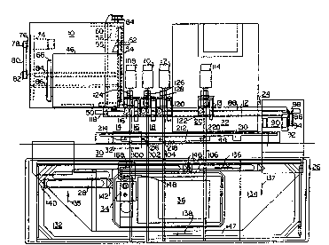
Re~erring to Figure 1, there is shown an optical
evaluation instrum_nt incorporating Zl sample handling
system according to the invention. The principal elements
of the sample handling systam include a cuvette storage and
loading mechanism 10, for supplying c:uvettes individually
to a cuvette transport mechanism 12, which advances the
cuvettes along a linear track 13 through a sample insertion
station 14, a plurality of reagent insertion stations 16,
18 and 20, an optical monitoring station 22 and fin lly, to
30 a cuvette disposal station 24. The sample handling system -
additionally includes a refrigerated housing 26, for
storing a plurality of evacuated collection tubes ~not
shown), which are transported via shuttles 28 through a
programming station 30, including a bar code reader 32, for -;
reading a preprin~ed bar code printed on the side of each
e~racuatod collection tube identif~ing the test sample and
.: '
wo~3~ 4~ PC~US90/0699
"~ 8 -
the test to be performed, and onto sample insertion station
14, which includes a piercer 34, for piercing the septum of
an evacuated collection tube for allowing a sample probe 36
(see Figure 2~ to be lowered into the sample collection
tube for aspirating a fluid sample which is to be ejected
into a reaction well of a cuv~tte located at sample
insertion station 14, as described in greater detail herein
below. Refrigerated housing 26, additionally encloses a
reagent chamber 36, which stores a plurality o~ reagent
containers (see Figures 5 and 6), which can be accessed by
reagent probes 38, 40 and 42 (see Figure 2), for aspirating
selective reagents and injecting them into reaction wells
located at the respective reagent insertion stations 16, 18
and 2 0 . As used herein, reagents include any reagent,
diluent, buff~!r, or activator wAich is required for any
given biochemical test being performed on the patient
sample according to a preprogrammad test protocol. A probe
washing sta~ion 44, is provided for washing the sample and
reàgent pro~es after each dispensing action.
Referring to Figures l and 4, cuvette storage device
10 includes a cassette frame 46, for receiving a cassette
of cuvettes arranged in the cassette in columns parallel to
the right and left hand sides of frame 46 in Figure 1. The
cassettes are preferably of the type described in concur
rently filed and copending U.S. patent application Serial
No. 07/443,95~, to Karp et al. and assigned to the owner of
the present application. ~ plan view of one such cuvette
50 is seen in a loadin~ position with respect to cuvette
transport mechanism 12. ~ pusher arm 52, driven by a lead
screw 54, loads cuvettes onto cuvette transport mechanism
12. A motor 56, whose shaft 58, is connected with a pulley
60 rotates a driving belt 62 which turns a pulley 64 for
driving lead screw 54. A fixed guide rod 55 is provided in
the usual manner for providing guidance and additional
support for pusher arm 52. After a column o~ cuvett2s is
completely loaded onto cuvette transport mechanism 12,
pusher arm 52 is retracted and a new column of cuvettes is
moved rightwardly (in Yigure 1) by way of a cassette column
. , . .. : : ., .; :. .. , ~. .. .
~`~I/I)~4~ PCT/U~90/06992
- 9 ~ 3
drive mechan.ism to be in line with pusher arm 52. The
cassette column drive mechanism includes a plate 66,
provided with fingers 68, extending through slots 70 in a
bottom support 72 of cassette frame 46. A rectangular
plate (now shown), is positioned between ~ingers 68 and the
left-hand most column of cassettes (not shown) in frame 46
for pushing the cassette columns in a rightward direction
in Figure l. Plate 66 is driven by way of a motor 74 whose
shaft 76 is connected to a pulley 78 which turns a driving
belt 80 connected to a further pulley 82 which turns a lead
screw 84, whose threads engage with plate 66. A fixed
guide rod ~6, i5 provided parallel to lead screw 84, for
guiding plate 66 in the usual manner.
Cuvette transport mechanism 12, includes a lead screw
88, which is clriven by way of a motor 90 whose shaPt 92 i5 `:
connected to a pulley 94 for turning a belt 96 which is
connected for driving a pulley 98 connected to lead screw
88. The cuvettes are each provided with an engaging means,
6uch as a ri~ having the same pitched angle as the threads
of lead screw ~8 which engage the lead screw threads when
placed in a loading position by pusher arm 52. A cuvette
50 is shown in the loading position engaging lead screw 88.
Cuvet~es of this type, which desirab:Ly have four reaction
wells, as shown by cuvette 50, are d:isclosed in the
aforementioned copendin~ patent appl:Lcation Serial No.
07/443,956, to Karp et al. Once engaged with lead screw
88, the cuvettes are ad~anced in a rightward direction in
Figure 1 along linear ~rack 13 ~hrough tha various s~ations
as described herein for injecting a sample volume and
reagents to create a reaction volume to be optically
monitored at the optical monitoring station. Desirably,
linear track 13 is t~mperature controlled for controlling
the temperature of the contents of the cuvette reaction
wells. For this purpose, linear trac': 13 is cooled on the
left side of a heat fIow restriction 15 shown in Fi~ure 2
by way of, for example a Peltier device (not shown) to ;.
maintain the temperature of the reaction well contents at
about 15C. On the right hand side of heat flow restric-
.. . . : : ~.~ . .. - ... .. . . . :
WO~ X4~4 ~ PC~/US90/06992
V
1 0
tion 15, lineax track 13 is heated by way of a heating
element 17, such as a resistive heat tape, applied to the
under side of the linear track for maintaining the tempera-
ture of the reaction well contents at body temperature.
Control signals for controlling motors 56, 74, and 90, for
turning respective lead screws 54, 84 and 88, to accomplish
the required incremental movements of pusher arm 52, plate
66, and cuvette 50, respectively, are received from a
central controller (not shown~ of the instrument in a
10 manner well understood by those skilled in the art. ,;
Sample probe 36, and reagent probes 38, 40 and 42 are
controllably mov~d along a horizontal path by way of
respective lead screws 100, 102, 104 and 106, driven by
respective motor assemblies 108, 110, 112 and 114. ~ .
Vertical movement for lowering and raising sample probe 36,
and reagent probes 38, 40 and 42, is accomplished by way of : .
respective vertical gear racks 116, 118, 120 and 122,
driven by coxresponding ~ertical motor and pinion assem-
blies 124, 126, 128, and 130, respectively. Horizontal
lead screw motors 108, 110, 112 and 114, and vertical rack
and pinion motors 124, 126, 128 and 130, are selectively
controlled by signals received from the instrument con- ;
troller (not shown) ~or controlling the horizontal and
vertical movement of the respective probes for aspirating
and disp nsing sample and reagents according to the test
protocol identified from the ~ar code of a given sample
collection tube read by bar code reader 32. Sample and
reagent aspiration and dispensing by probes 26, 28, 30 and
32 is accomplished ~y way of positive displacement pumps
(not shown) connected to the respective probes in a manner
understood by those skilled in the art.
Re~rigerated housing 26, comprises a double walled
insulated enclosure 131, and a cooling system 133,
preferably of the ducted type, for circulating cooling air
within housing 26 for maintaining the temperature of sample
collection tubes (not shown) mounted in shuttles 28 and
reagents in reagent chamber 36 at a temperature between 4
and 80C.
,
.
, - - - - -, ,, . ... ~
~, '... .. . : ,
..
W~')I//)~46~ PC~/US90/06992
~8~ ~
Referring to the plan view shown in Figure l,
refrigerated housing 26, has left and right chambers 132
and 134, respectively, connected by passages 146 and 147
for storing and transporting shuttles 28, which are caused
to move in a clockwise direction, as shown by arrows 135 to
138. Each shuttle 28 is provided with means for carrying a
plurality of evacuated sample collection tubes of the type,
for example, made by Beckton Dickinson of Rutherford, New
Jersey, and sold under the brand name Vacutainer. The
configuration of shuttles 28, and the mechanism ~or
transporting the shuttles is disclosed in detail, for
example, in U.S. Patent No. 3,418,084 ~o Allington.
Briefly, each shuttle 28 has complimentary camming
surfaces 140 and 142 formed at the opposite ends thereof.
Shuttles 28 are disposed in rows in the respective chambers
132 and 134. A drive mechanism (not shown) comprising
gears which mesh with gear tracks 29 on the bottom of the
shuttles 28 tFigure 2), drive the shuttles through passages
146 and 147 in opposite directions. The shuttle drive
mechanism causes a driven shuttle to push the shuttle in
front of it and the camming surfaces effect a lateral
displacement in the manner described by the above-
referenced patent to Allington.
The shuttles are transported, one behind the other, in
passages 146, so that the evacuated collection tubes are
passed first through programming station 30 where har code
reader 32 reads a previously-applied bar code on the side
o~ the evacuated collection tube to identify the sample and
the test to be performed. The information read by bar code
reader ~2 is fed to the instrument controller (not shown~
for controlling subsequent movement of the sample and
reagent probes for filling a reaction well of a cuvette
transported by cuv tte transporting mechanism 12 through
the respective sample and reagent s ations.
Aftex having its bar code read, the evacuated collec-
tion tube is moved, by way of the shuttle and shuttle drive
mechanism, a precise distance to place the evacuated
O~1/0~464 ,1~ PCT/US90/06992
~ 3~
h" - 12 -
collection tube in line with piercer 34. The precisepositioning of the shuttle is accomplished by way of an
electro-optical sensing mechanism 148 (Figure 1), which
passes a sensing beam through spaced passage~ 150 (Figure
2), provided in the base of shuttles 28, for sensing when
the shuttle is in the appropriate position.
Referring to Figure 3, piercer 34 includes a piercing
tube 152 having a sharp angled end 154, canted at approx-
imately the same angle as the tip of a conventional
hypodermic needle, for piercing a septum 156 of an
evacuated collection tube 158. Piercing tube 152 is
moun~ed in a support 160 which engages a ~ertical lead
screw 162 which is connected by way of a belt and pulley
system 164 to a motor 166 for driving lead screw 162. With
appropriate movement of lead screw 162, piercing tube 152
is caused to be lowered for piercing septum 156 or to be
removed thereErom. A holding mechanism 159 holds tube 158
in place while piercing tube 152 is inserted and withdrawn.
Piercer 34 has an opening 168 (Figure 1) at the top
concentrically aligned with piercing tube 152, so that when
sample probe 36 is aligned with piercing tube 152 a pathway
is provided for lowering the sample probe into an evacuated
collection tube 158, for aspirating a ~luid sample there-
from.
Reagent chamber 36 is shown in greater detail in
Figures 5 and 6. As shown in these Figures, a reagent
container support plate or tray 170, is provided for
supporting a plurality of reagent containers or cup~ 172,
of varying capacities. A reagent cover 176, of ap-
proximatsly one half inch thickness, is placed over reagent
container support plate 170. Reagent cover 176 is provided
with reagent probe holes 178 positioned above respactive
ones of reagent containers 172. Probe holes have a diameter
(approximately 3mm) slightly larger than the diameter of
reagent probes 40 and 42 for permitting the pro~es to be
lowered into selected ones of the reagent containers.
Reagent cover 176 servas as an anti~evaporation cover for
retarding or pre~en'~ng ~vaporation of the reagents in
.
- ....... ., ~ ............... : . . . .
. . : : . . .
W09l/~J~ PCT/US90/OS~92
- 13 - ~S~3
reagent containers 172 while still allowing access to the
reagents through probe holes 178. The anti-evaporalion
cover additionally serves to retard rapid temperature
shifts by providing a barrier between different temperature
zones. Although there are multiple holes in the anti-
evaporation cover, it is of sufficient depth to provide the
tortuosity necessary to retard or prevent evaporation of
li~uids. Desirably, reagent cover 176 is provided with
locator pins 180 for accurately positioning the cover over
the reagent containers and in alignment with the horizontal
tracks of reagent probes 38, 40 and 42.
Probe washing station 44, comprises a trough 210,
containing a cleaning solution such as bleach. An addi- -
tional trough 212 is provide for receiving waste fluids and
cleaning solution from the probes during the washing
process. Trough 212 is provided with a plurality of riser
platforms 214, 216, 218 and 220, each containing a concave
recess and serving as a deflector for fluid and cleaning
solution expelled from a probe. A~ter a probe dispenses
its fluid into a reaction well in a cuvette, and before the
probe is positioned to aspirate sample or reagent as the
case may be, the probe is positioned over trough 210 for
aspirating cleaning solution. The probe is then positioned
over the corresponding deflector where primer fluid, such
as water, is forced through the probe interior for expell-
ing the cleaning solution, followed by primer li~uid,
against the deflector thereby creating a fountain effect
which washes the outside of the probe. The waste solutions
are captured by trough 212 and vented away through a waste
30 ou~let (not shown). A more detailed description of probe - ~ -
washing station 44 is described in co-pending`and concur-
rently filed U.S. pate~t application Serial No. 07/443,954,
to Ho~fman at al.
Optical monitoring station 22 comprises a multichanne
1 optical monitoring system of the type described in detail
in the above-mentioned copending U.S. patent application ~ ;-
Serial No. 07/443,952 to Swope et al. Briefly, and with
rsfersnce to Fiouros 2 and 3, the optlcal monitoring
. .
" ' ' ' ,; ' ' ''' ' '. .: " ,'' .' . ' , ' ''"' , '' ' '' ~ " ' ,'' '":'': ' , ' , ' . ' :' ' '." ' ; ' ' ' '
WO91/0~ ~ ~ `' P~T/US~0/06992
- 14 -
system includes a broad band light source 1g2, which passes
light through a slit (not shown). A collimating lens 184,
collimates the beam to form a slowly diverging b~am 186
which is folded by reflecting mirrors 188, 190 and 192.
Following mirror 192 is a mask (not shown), which includes
a plurality of linear-ally spaced apertures ~or dividing
beam 186 into a corresponding number of beams, each
defining an optical path or channel 194, as schematically
illustrated in Figure 2. The optical paths or channels 194
are linearally spaced along the track of cuvette transport
mechanism 12 so that each reaction well of a cuvette passes
from channel-to-channel as cuvette transport mechanism 12
incrementally advances the cuvettes along the linear path.
The light beams passing through th~ reaction wells of the
cu~ettes are passed through a rotating shutter 194 which
sequentially passes the light beams to diffraction gratings
196 where the beams are diffracted and focused by focusing
lenses 198 onto respective photodiode arrays 200 which are
subsequently electronically scanned for reading electronic
signals which correspond to the spectral distribution of
the beams transmitted by the respective reaction volumes
contained in the reaction wells of the cuvettes. In one
specific implementation, the optical monitoring system
includes 20 channels, and the rotating shutter operates to
sequentially pass the beams within groups of five beams, so
that only one beam from each group of five beams is passed
onto a photodiode array at any one time. The focusing
lenses operat~ to focus each group of five beams onto a
respective on~ of photodiode arrays 200.
The operation of the sample handling system will now
be described in the context of one specifio implementation
of the invention, it being understood that the invention is
not limited to this particular implementation.
Operation of the sample handling system according ko
the inven~ion is centered on linear track 13 along which
cuvettes are advanced from station to station by lead screw
88. The basic timing and sequencing of the system is based
W~ h~t Pcr/us~o/n6g~2
- 15- ~ 413
on advancing the cuvettes along the linear track a distance
equal to the distance between successive reaction wells.
Initially, an operator loads cuvettes into the
instrument by placing a cassette of cuvettes into cassette
frame 46. Each cassette holds, for example, 120 cuvettes.
The cuvettes are automatically moved ~rom the cassette onto
linear track 13 by ar~ 52 where they engage lead screw 88.
Each cuvette preferably has four 1/4 inch reaction wells.
Lead screw 88 is activated every fifteen seconds to move
the cuvettes in 0.25 inch increments in 0.1 seconds. The
instrument controller monltors each cuvette by the timing
associated with the lead screw. Lead ~crew 88 advances the
cuvettes to the first station, i.e., sample insertion
station 14, where a sample is delivered to a reaction well
aligned with sa~ple probe 36. Two minutes later, the load
reaction well of the cuvette arrives at the first reagent
delivery probe 38 where diluent or a reagent is added,
depending on the test being carried out. The second
reagent probe 40 is located at the four minute position
where an activator can be added. Five minutes later the
loaded reac~ion well of the cuvette reaches the third
reagent probe-42 where a reagent is added and the reaction
monitoring ~egins. The reaction is monitored electro-
optically by optical monitoring syst:em 22 which measures
changes in the optical transmission of the reaction volume
as the clot forms or as the chromometric reaction proceeds.
As the cuvette is moved along the track, the optical
monitoring co~tinues ~or twenty con~ecutive stations, that i"!~ ';
is, for 300 seconds. Following the optical monitoring
station the cuvette leaves the track and is sent to a waste
container (not shown~
Patient plasma samples are stored in re~rigerated
housing 26 in the original evacuated blood collection tubes
used to obtain the patient's sample which has been
previously spun down to o~tain the plasma and bar-coded for
patient identificatlon and test protocol to be per~ormed.
The evacuated sample collection tu~es are placed in the ;~
holders of shuttles 28 and advanced by the shuttle drive
... .. .
.. ,; ' .,'; .' ' ' `, . . , ' "., . ' ~'` ' ., .. .,, ' . ,' . ', " ~ ' ' .. '; . ' '
,
.....
WO~I/0~464 ~`- P~-r/US90~0699Z
- 16 -
mechanism to the bar code reader. The evacuated sample
collection tuhes can be arranged in any order since the bar
code on each sample collection tube allows the instrument
to automatically correlate a patient with a given sample.
The bar code read by bar code reader 32 also programs the
instrument controller for determining the amount of sample
to be aspirated by sample probe 36, the number of reaction
wells to be filled with the sample, and the amounts and
types of reagents/ buffers/additives/activakors to be
injected into the respective reaction wells by reagent
probes 38, 40 and 42. Subsequent to programming station
30, a sample collection tube is advanced to piercer 34
where piercing tube lS2 is caused to pierce the septum of
the evacuated sample tube to allow sample probe 36 to be
lower~d into the sample collection tube to aspirate a
programmed amount of sample. Sample probe 36 is next "
removed from the evacuated sample collection tube and
horizontally moved over a reaction we.11 positioned at
sample insertion station 14 and lowered into the reaction
well where a programmad amount of sample is expelled into
the reaction well. The evacuated sample collection tubes
can be removed from refrigerated hous;ing 2~ at any time
after sample aspiration is complete; however, because the
samples are maintained at lowered temperatures, they can be
retained for further testing without having to be im-
mediately removed from its shuttle. Reagent chamber 36
stores various controls, diluents, activators and reagents.
Xn one implementation of the system up to twenty-two
containers of these materials are stored in reagent chamber
36. All con~ainers arP held to a temperature of about 7 C
and the reagents are heated, if necessary, in the reagent
probe as they are being dispensed. -
Pumping in all cases is performed with positive dis-
placement syringe pumps operatively connected with xespec-
tive ones o~ the probe. No manipulation of pump tubing isrequired as is the case with peristaltic pumps. A reagent
is dispensed into a reaction well in a manner that promotes
~i~in~ ~ith the sample and other contents of the reaction
~:
W~ 8464 PCT/US90/06992
- 17 ~ 3
well. The reagent temperature and volume are controlled by
the instrument controller.
Desirably, fluid level sensing is utilized to control
the height of a reagent probe relative to the level of a
reagent in its container and relative to the contents of a
reaction well. This permits bringing the outside of a
probe into contact with a minimum guantity of reagent.
This, in turn, reduces the possibility for carry-over.
Additionally, level sensing is used to control the hei~ht
of a probe above the fluid level while dispensing in order
to minimize carry-over and to maximize mixing.
It will be understood that the above description of
the present invention is susceptible to vario~!s modifica-
tions, changes and adaptations, and the same are intended
to be comprehended within the meaning and range of
equivalents of the appended claims.
...
. . . ~ - . :, - . . . ,: . - . . - . . . :