Sélection de la langue

Search

Sommaire du brevet 2069163 

Énoncé de désistement de responsabilité concernant l'information provenant de tiers

Une partie des informations de ce site Web a été fournie par des sources externes. Le gouvernement du Canada n'assume aucune responsabilité concernant la précision, l'actualité ou la fiabilité des informations fournies par les sources externes. Les utilisateurs qui désirent employer cette information devraient consulter directement la source des informations. Le contenu fourni par les sources externes n'est pas assujetti aux exigences sur les langues officielles, la protection des renseignements personnels et l'accessibilité.

Disponibilité de l'Abrégé et des Revendications

L'apparition de différences dans le texte et l'image des Revendications et de l'Abrégé dépend du moment auquel le document est publié. Les textes des Revendications et de l'Abrégé sont affichés :

  • lorsque la demande peut être examinée par le public;
  • lorsque le brevet est émis (délivrance).
(12) Demande de brevet: (11) CA 2069163
(54) Titre français: SEMELLE ORTHOPEDIQUE
(54) Titre anglais: ORTHOPAEDIC INSOLE FOR A FOOT
Statut: Réputée abandonnée et au-delà du délai pour le rétablissement - en attente de la réponse à l’avis de communication rejetée
Données bibliographiques
(51) Classification internationale des brevets (CIB):
  • A43B 13/38 (2006.01)
  • A61F 5/14 (2006.01)
(72) Inventeurs :
  • HYVAERINEN, TUOMO (Finlande)
  • ROMO, REIMA J. (Finlande)
(73) Titulaires :
  • KARHU-TITAN OY
(71) Demandeurs :
  • KARHU-TITAN OY (Finlande)
(74) Agent: GOWLING WLG (CANADA) LLP
(74) Co-agent:
(45) Délivré:
(22) Date de dépôt: 1992-05-21
(41) Mise à la disponibilité du public: 1992-11-30
Licence disponible: S.O.
Cédé au domaine public: S.O.
(25) Langue des documents déposés: Anglais

Traité de coopération en matière de brevets (PCT): Non

(30) Données de priorité de la demande:
Numéro de la demande Pays / territoire Date
912588 (Finlande) 1991-05-29

Abrégés

Abrégé anglais


Abstract
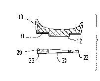
The invention concerns an orthopaedic insole for a
foot in shoes, which orthopaedic insole is intended
to correct faulty postures of a foot by supporting the
foot in the way required by the correction of the
faulty posture. The orthopaedic insole comprises a
body (10) of the insole and an adjusting piece (20)
separate from the body (10), which adjusting piece
is supposed to be attached to a space (11) formed for
said adjusting piece (20) into the bottom face of the
insole body (10).
(Fig. 3)

Revendications

Note : Les revendications sont présentées dans la langue officielle dans laquelle elles ont été soumises.


CLAIMS:
1. Orthopaedic insole for a foot in shoes, which orthopaedic insole is intended to
correct faulty postures of a foot by supporting the foot in the way required by the
correction of the faulty posture, c h a r a c t e r i z e d in that the orthopaedic
insole comprises a body (10) of the insole and an adjusting piece (20) separate from
the body (10), which adjusting piece is supposed to be attached to a space (11)
formed for said adjusting piece (20) into the bottom face of the insole body (10).
2. Orthopaedic insole for a foot as claimed in claim 1, c h a r a c t e r i z e d in
that the space (11) formed into the insole body (10) for the adjusting piece (20) is
substantially symmetric in relation to the longitudinal axis (A-A) of the insole body
(10).
3. Orthopaedic insole for a foot as claimed in claim 1 or 2, c h a r a c t e r i z e d
in that said adjusting piece (20) is substantially symmetric in relation to its longitudi-
nal axis and has a shape that substantially corresponds to the shape of the space (11)
that has been formed into the insole body (10) for the adjusting piece, and that the
adjusting piece (20) is arranged also to fit into said space (11) upside down.
4. Orthopaedic insole as claimed in any of the preceding claims, c h a r a c t e r -
i z e d in that the adjusting piece (20) is shaped so that its second side edge (23) is
substantially thicker than its first side edge (22), so that the cross-sectional form of
the adjusting piece (20) is substantially wedge-shaped.
5. Orthopaedic insole as claimed in any of the preceding claims, c h a r a c t e r -
i z e d in that into the body (10) of the orthopaedic insole, into the space (11)
provided for the adjusting piece (20), a projection (12) has been formed, and that, in
a corresponding way, an opening (21) has been formed into the adjusting piece (20),
into which opening said projection (12) has been arranged to fit.

6. Orthopaedic insole as claimed in claim 5, c h a r a c t e r i z e d in that said
projection (12) in the insole body (10) and said opening (21) in the adjusting piece
(20) have been formed onto the longitudinal axis (A-A) of the insole.

Description

Note : Les descriptions sont présentées dans la langue officielle dans laquelle elles ont été soumises.

~69~6~
Orthopaedic insole for a foot
S The invention concerns an orthopaedic insole for a foot in shoes, which orthopaedic
insole is intended to correct faulty post~res of a foot by supporting the foot in the
way required by the correction of the faulty posture.
In a mechanical examination, a human foot is a highly complicated construction, for,
10 on one hand, the foot must be resilient in order that it could adapt itself to the
variations in the environment and in the ground, however, so that, at the same time,
it provides the body with adequate support and balance. On the other hand, the foot
should, however, be sufficiently rigid to provide an adequate friction in relation to
the ground surface, so that the horizontal forces of acceleration and deceleration that
15 arise from the movements of the body can be transferred through the foot.
A number of studies have been performed concerning the foot, and in these studies
it has been noticed that only about 40 % of people have so-called "normal" feet,whereas the rest have various faults of posture in their feet. Faulty postures of feet
20 cause a disturbance in the state of loading of the body and a state of extra strain,
which is experienced by the person as disagreeable and which may quite frequently
result in pains in the foot, ankle, knee, or in the lumbar region of the back. Faulty
postures of feet are commonly corrected by means of various orthopaedic insoles and
orthopaeclic shoes, and, in recent years, attempts have been made to develop methods
25 for the selection of such orthopaedic insoles ancl shoes.
Usually, an orthopaedic insole that regulates the functioning of a foot is manufactured
in a certain standard shape. For each type of functioning of a foot, there is a separate
insole model of its own. This is why, for the manufacture, a series of moulds of its
30 own is required for each model. In such a case, the manufacturer and the retail dealer
must keep all models of every size on stock, which results in a high increase in the
costs of manufacture and sale both for the manufacturer and for the retail dealer.

The object of the present invention is to provide an orthopaedic insole of a novel
type, by whose means the number of the series of moulds needed in the rnanufacture
of the orthopaedic insoles and the number of stock items of finished products are
S reduced. In view of achieving this, the invention is mainly characterized in that the
orthopaedic insole comprises a body of the insole and an adjusting piece separate
from the body, which adjusting piece is supposed to be attached to a space formed
for said adjusting piece into the bottom face of the insole body.
10 The most important advantage of the invention over the prior-art orthopaedic insoles
is exactly therein that the body of the insole can be manufactured as identical for all
foot types, in which case an essentially lower number of series of moulds are
required. The correction required by the type of functioning of the foot can be
produced by means of a separate adjusting piece, which can be attached to the body
15 of the insole and which adjusting piece makes the insole suitable for foots of different
types of functioning. The further advantages and characteristic features of the
invention come out from the following detailed description of the invention.
In the following, the invention will be described by way of example with reference
20 to the figures in the accompanying drawing.
Figure 1 is a schematic perspective view of the body of an orthopaedic insole inaccordance with the invention and of an adjusting piece to be attached to same.
25 Figure 2 shows the body of the orthopaedic insole viewed from the bottom.
Figure 3 is a schematic sectional view taken along the line III-III in Fig. 1.
Figure 4 is a side view of the body of the orthopaedic insole and a sectional view of
30 the adjusting piece for the orthopaedic insole taken along the line IV-IV in Fig. 1.
Thus, the orthopaedic insole in accordance with the invention consists of a body 10
- . . .
' ,
' .

2 ~ 3
of the insole and of an adjusting piece 20 to be attachecl to ~he body. Into the body
10 of the orthopaedic insole, into the bottom face of the body, a space 11 syrnmetric
in relation to the longitudinal axis A-A of the body 10 has been formed for the
adjusting piece ~0. Said space 11 for the adjusting pie~e 2û extends substantially
5 from the rear part of the body 10 of the orthopaedic insole, i.e. from underneath the
heel, to the area of the foot arch. In the embodiment as shown in the figures, onto
the body 10 of the orthopaedic insole, substantially in the area of the heel on the
longitudinal axis of the body part, a projection 12 that projects outwards from the
space 11 provided for the adjusting piece has been formed additionally so as to align
lQ the adjusting piece 20.
The adjusting piece 20 can be fixed to the space 11 provided for it, for exarnple, by
gluing or by means of tape. The adjusting piece has been shaped so that by its means
the insole becomes suitable for foots of different types of functioning. Attempts have
15 been made to illustrate this in particular in Fig, 3. According to Fig. 3, the adjusting
piece 20 has been shaped so that its second side edge 23 is substantially thicker than
its first side edge 22. With the exception of this difference in the thicknesses of the
edges, the adjusting piece 20 has been shaped symmetric in relation to its longitudinal
axis so that it can also be used upside down as attached to the body 10 of the insole.
20 Thus, for a foot with excessive pronation, the adjusting piece is placed so that the
thicker second side edge 23 of the adjusting piece 20 is placed at the inside edge of
the insole. In a corresponding way, for a foot with insuff1cient pronation, the
adjusting piece is turned over, so that the thicker side edge 23 is placed at the outside
edge of the insole. Moreover, as is shown in the figures, an opening has been formed
25 into the adjusting piece 20, which opening fits onto the projection 1~ formed onto the
body lO of the insole. In the longitudinal sectional view shown in Fig. 4, it is seen
that the maximum elevation 24 in the adjusting piece 20 has been formed approxi-mately at the front edge of the heel, where correction of the foot posture is exactly
needed. To provide di~ferent extents of correction of the foot posture, it is possible
30 to make additional pieces or adjusting pieces 20 that are provided with different
degrees of inclination~ i.e. shaped so that the difference in thickness between the side
edges of the adjusting piece 20 is different.

Above, the invention has been described by way of example wi~ reference to tbe
figures in ~he accompanying drawing. The inven~don is, however, not confined to the
exemplifying embodiments shown in the figures alone, but different alterna~ive
S embodiments of the invention may show variation withill the scope of the inventive
idea defined in the accompanying patent claims.
.
,
. . .
.
: . . ,
~ : .
.. . . .

Dessin représentatif
Une figure unique qui représente un dessin illustrant l'invention.
États administratifs

2024-08-01 : Dans le cadre de la transition vers les Brevets de nouvelle génération (BNG), la base de données sur les brevets canadiens (BDBC) contient désormais un Historique d'événement plus détaillé, qui reproduit le Journal des événements de notre nouvelle solution interne.

Veuillez noter que les événements débutant par « Inactive : » se réfèrent à des événements qui ne sont plus utilisés dans notre nouvelle solution interne.

Pour une meilleure compréhension de l'état de la demande ou brevet qui figure sur cette page, la rubrique Mise en garde , et les descriptions de Brevet , Historique d'événement , Taxes périodiques et Historique des paiements devraient être consultées.

Historique d'événement

Description Date
Inactive : CIB de MCD 2006-03-11
Le délai pour l'annulation est expiré 1995-11-21
Demande non rétablie avant l'échéance 1995-11-21
Réputée abandonnée - omission de répondre à un avis sur les taxes pour le maintien en état 1995-05-22
Inactive : Demande ad hoc documentée 1995-05-22
Demande publiée (accessible au public) 1992-11-30

Historique d'abandonnement

Date d'abandonnement Raison Date de rétablissement
1995-05-22
Titulaires au dossier

Les titulaires actuels et antérieures au dossier sont affichés en ordre alphabétique.

Titulaires actuels au dossier
KARHU-TITAN OY
Titulaires antérieures au dossier
REIMA J. ROMO
TUOMO HYVAERINEN
Les propriétaires antérieurs qui ne figurent pas dans la liste des « Propriétaires au dossier » apparaîtront dans d'autres documents au dossier.
Documents

Pour visionner les fichiers sélectionnés, entrer le code reCAPTCHA :


Pour visualiser une image, cliquer sur un lien dans la colonne description du document. Pour télécharger l'image (les images), cliquer l'une ou plusieurs cases à cocher dans la première colonne et ensuite cliquer sur le bouton "Télécharger sélection en format PDF (archive Zip)" ou le bouton "Télécharger sélection (en un fichier PDF fusionné)".

Liste des documents de brevet publiés et non publiés sur la BDBC .

Si vous avez des difficultés à accéder au contenu, veuillez communiquer avec le Centre de services à la clientèle au 1-866-997-1936, ou envoyer un courriel au Centre de service à la clientèle de l'OPIC.


Description du
Document 
Date
(aaaa-mm-jj) 
Nombre de pages   Taille de l'image (Ko) 
Page couverture 1992-11-30 1 23
Abrégé 1992-11-30 1 14
Revendications 1992-11-30 2 47
Dessins 1992-11-30 2 23
Description 1992-11-30 4 151
Dessin représentatif 1999-05-03 1 3
Taxes 1994-04-26 1 39