Note : Les descriptions sont présentées dans la langue officielle dans laquelle elles ont été soumises.
WO 92/076:26 l'CI'/GB91/01901
2~5~;3
FALL-ARREST APPAE~ATUS
This invention relates to fall-arrest apparatus for
attachment to a fixed anchorage, which apparatus comprises a
drum for holding a cable or other extendable anchorage line
and a drum brake which functions automatically to brake the
drum if it exceeds a given unwinding speed.
Apparatus of this kind have long been used for prote~ting
wor}cers who are exposed to the rlsk of falling from an
elevated work site. Examples of such apparatus are described
in UK Patents 851981 and 1552667.
The drum brake employed in apparatus of the kind referred
to may be of centrifugal type, comprising braking elements
which bodily xotate with the drum. The drum is biased by
torsion spring means in the winding direction so as
automatically to take up any slack in the anchorage line.
The said drum braking elements are normally held retraoted by
springs but if the drum should reach an unwinding speed above
a certain value they move against the action of their springs
into positions;in which they cause deceleration of the drum
to rest. -
~
.. . . .
It is known ~see e.g. United States Patents Nos 4489919and 4846313) to provide apparatus of the kind referred to
with a winch mechanism by which the drum can be manually
re-wound to xaise a fallen suspended load. The winch handle
drives the drum via a~reduction gearing affording a
substantial mechanical advantage. As~the drum begins~to be
rotated,-the centrifugal~drum~brake mechanism disengages. In
order to prevent the load ~rom descending under its own
weight as soon as winding force on the winch handle;is
relaxed,~ a ratchet~operates between the winch handle and-the
drum housing to prevent any reverse movement of the winch
....~; :
.,
:~ :
:
WO 92/07626 PCI /GB91/019OI
Z~ 35~3
handle. It follows that the winch mechanism cannot be used
for lowering a suspended load unless the ratchet is rendered
inoperative with consequent risks of the load sus~aining an
arrested fall due to loss of control of the winch handle by
the operator. That is a disadvantage. For example, in the
case of the fall of a worker using the fall-arrest apparatus,
circumstances may be such that recovery and care of the
worker could be more speedily effected if the worker could be
lowered to the ground in a controlled manner with complete
safety.
United States Patent 4589523 and ~uropean Patent 152041
describe fall-arrest apparatus having a winch mechanism which
can be selectively operated in winding or unwinding mode for
raising or lowering a fallen load suspended from the
anchorage line. This is made possible by a progressively
acting screw-type friction clutch incorporated in the
transmission between the winch handle and the anchorage line
drum. Operation of the winch handle in winding or unwinding
mode cause clockwise or anti-clockwise movement of a clutch
clamping nut which is in screw engagement with the winch
shaft and consequently causes approach or separating movement
of friction rings of the clutch. Turning of the winch handle
in the winding mode causes the clutch rings to become clamped
together so that winding torque is transmitted to the drum,
in consequence of which the centrifugal drum brake becomes
released. Continued ~urning of the winch handle in the
winding mode causes the load to be winched up. The
frictional resistance of the clutch, together with the
operation of a pawl and ratchet lock associated with the
winch~shaft, prevents the drum from unwinding under the
suspended load whenever the winding force on the winch handle
is relaxed. Eor lowering the suspended load the winch is
operated in either of two ways. In one way, the wincA handle
is first turned in the winding Mode sufficiently to cau~e
release of the centrifugal drum brake as aforesaid and is
then turned in the reverse direction until the clamping force
, ~ , . ~, ~ . ,: . . .
W092/07626 PCT/GB91/01901
35~13
on the clutch rings becomes so reduced that the clutch slips
under the torque applied by the suspended load. Thereafter a
very nice control of the winch handle is necessary if the
lowering of the load is to proceed reasonably smoothly. In
practice this is difficult. Unwinding motion of the drum in
consequence of the clutch slippage tends to tighten the
clutch rings again and in practice the anchorage line becomes
unwound discontinuously with periods of acceleration followed
by periods of gradual deceleration. In the alternative way
of lowering the suspended load, the winch handle is turned in
the unwinding mode without first turning it in the opposite
direction to release the centrifugal drum brake. But in this
case the winch handle has to be turned to release the
clamping force on the clutch rings and to bring the clutch
clamping nut to the limit of the thread on the winch shaft '~
before the winching-down movement can commance. Once the
clamping nut has reached the limit of the thread and cannot
therefore be turned further in that direction relative to the
winch shaft, continued operation of the winch handle in the
unwinding mode drives the anchorage line drum in the
unwinding direction via the winch shaft, against the
resistance of the màin fall-arrest drum brake.
Considerable skill and experience in the operation of the
winch of that appaxatus is required in order that it can be
confidently used to winch down a suspended load in a well
controlled manner due to co~trolled slippage of the winch
clutch. Incorrect use of the winch handle can result in
rapid;fall of the load over a considerable distance before it
becomes arrested. The ris~ is in~olved in partiaular when
winching down a suspended load of~light weight, such for
example as a small child. Falls~can also occur even when
winching-down a load while the drum brake is engaged. Should
the descent of the load become interrupted, e.g. due to the
load encountering a ledge or other obstruction or to snagging
~, .
. . ' .
~. . .. . ' . . ' ' ~ ~
~092/07626 PCT/GB91/01901
" ,~
.. ..
2~ 4
of the anchorage line on a protru~ion, so that u~wlnding
torque ceases to be transmitted to the drum via the anchorage
line, the drum wlll start to rewind under the biasing force
of the drum spring~ Consequently the centrifugal drum brake
will become disengaged and when the load or snagged anchorage
line is freed from the obstruction, the load will undergo an
arrested fall.
The present invention provides apparatus with a winch
mechanism by means of which a suspended load can easily be
winched up or down in a smooth nicely controlled manner, and
without an attendant risk of a potentially damaging fall of
the load.
According to the present invention there is provided
fall-arrest apparatus ~or attachment to a fixed anchorage,
which apparatus comprises a drum for holding a cable or other
extendable anchorage line, a drum brake which functions
automatically to brake the drum if it exceeds a given
unwinding speed, and a winch mechanism which can be coupled
to the drum to permit manual rotation of the drum in winding
or unwinding mode ~or raising-or lowering a load suspended
from said anchorage line, said winch mechanism having
~associated braking means for holding a said load against
~descent under its own weight; characterised in that said
winch braking means comprises xelatively rotatable~brake
elementsj means which.permanently holds such elements in
contact~under-pressure to:maintain:a predetermined ~rictional
- resistance to such relative rotation, and a one-way torque
coupling which whenever and ~or as long as the.winch
mechanism i~ coupled to~the drum, prevents unwi.nding motion
o~ the:drum otherwise than against the said resistance to
.. relative rotation of~said:brake elements~ -.
.: :.. ..
: ,~
i
:
. ,,
WO9~/07626 ~ PCT/GB9l/o
The apparatus affords a high degree of safety by virtue
of the permanent effectiveness of the winch brake whenever
and for as long as the winch mechanism is in use or is set
for use. No particular care or skill is required for
operating the winch in either its winding or unwinding mode.
The winching-up or winching-down of a load can be safely
effected by operating the winch handle at any speed
convenient to the operator.
The resistance afforded by the winch brake should of
course be sufficient to resist rotation of the drum under the
greatest load which may be suspended from the anchorage line
during use of the apparatus for its intended purpose. The
invention is intended primarily for embodiment in a personnel
fall-arrest apparatus. For that field of use, the winch
brake should preferably be able to resist rotation of the
drum under the torque exerted by a weight in excess of 140 Kg
when it is hanging from the anchorage line. Preferably the
pulling force which has'to be exerted on the anchorage line
in order to overcome the resistance of the winch brake is at
least 180 Kg.
In the case that the load has been arrested during a
fall, and the winch is operated in the unwinding mode while
the fall-arrest brake retains its operative condition, the
unwinding has to take place against the combined resistances
of the''drum brake" and the winch brake. That combination of
resistances can howe~er'quite 'easily be overcome by virtue
the~ act'that the unwinding is actually assisted by the load
itseLfr especially'so`if the'winch mechanism affords a
significant mechanical advantage to the winch'handle. ' The
said mechanical advantage is pre~erably in excess of 4~
the winch handle'is initially'opera~ed in the winding mode,
just sufficiently to allow the drum brake'to disengage, the
.
j winching-down will then take place against sole resistance of
the winch brake.
,:
~ .
,
: ~'
~''
.
. ' :' .'
: : .
WO 92/07626 P~/GB91/OlgOI
Z~5~ 6 ,
The winch brake will also afford the sole braking
resistance in the case that the winch is operated for winding
down a suspended load which has not undergone an arrested
fall causing application of the fall-arrest brake.
Because of the presence of the one-way torque coupling,
when the winch is operated in the winding mode for winching
up a load, whether or not it has been subject to a
fall-arrest, the winch brake does not oppose the winching up
operation. However, that brake is effective for holding
the load against descent whenever the winding force on the
winch handle is relaxed.
Preferably the winch mechanism is arranged so that the
operative direction of rotation of the winch handle is
clockwise in one transmission mode and anti-clockwise in the
other mode. The operation of the winch handle can therefore
be according to natural usage.
The apparatus may incorporate supplementary winch brake
elements which can be put into effect for holding the drum
against rotation in the unwinding mode if the apparatus is
used or is intended to be used for carrying exceptionally
heavy loads.
,~ , , - .
, ,~ reversible ratchet mechanism may be pro~ided between
the winch,handle and a driven shaft to permit the drum to be
wound or unwound by rocking motion of,such~handle. A control
member conveniently accessible to an operator can be provided
for setting this,ratchet mechanism for turning the drum
clockwise or anticlockwise. The winch brake will
ef~ectively hold any ~uspended load against descent under its
own weight whanever and for as long as said ratchet mechanism
is in a neutral position. ~ , , "- ", ;
: ~.
~. .
W092/07626 ~z~95~3 ` ; PCT/GB91/01901
(` 7
Certain embodiments of the invention will now be
descrlbed with reference to the accompanying drawings, in
which: .:
Fig. 1 is a sectional elevatlon of part of an apparatus
according to the inve~tion;
Fi~. 2 shows on a larger scale a detail of the braking ..
means associated with the winch mechanism of that apparatus; ::
Fig. 3 is a sectional elevation of that braking means, at
right angles to Fig. 2;
Fig. ~ shows ano~her detail of the winch mechanism of the
same apparatus; and
.
Figs. 5 and 6 are a part sectional front elevation and a
sectional side ele~ation respectively of part of another form
of winch braking means
. .
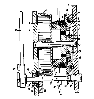
As appears in Fig. 1, the apparatus comprises a cable
drum 1 which is rotatable on a shaft 2. A cable 3 is wound
onto the drum. The shaft 2 is endwise supported in opposed
walls 4r5~ forming par~:of an outer casing of the apparatus.
The casing can be attached to an elevated fixed anchorage.
spiral spring 6 is connected at one end to that shaft and at
the other end to the drum. That spring biases the drum in
the winding direction so that when cable which has been
.pullad out from.the .apparatus is released,.it becomes
automatically rewound onto.the drum. : : `.
~ .
..~.~ There is a ~all-arrest .drum bra~e comprising a rotatable
brake disc 7 having a peximetral flange 8~. and co-operating
fixed brake rings 9,10 between which that ~lange is
, ~.
:::
.. .. .. . . .
W092/07S26 2~6~5"~3 : ; ~ . PC~/GBgl/olgOl
sandwiched under pressure exerted by a clamping ring 11.
This ring is connected to the caslng wall 5 by clamping bolts
(not shown). The rotatable disc 7 has an annular recess 12
opening towards the drum. The outer side wall of this recess
is shaped to provide a series of ratchet teeth 13. The drum 1
carries pivoted pawls 14,15 for engaging that ratchet. The
pawls are normally held out of engagement with the ratchet by
springs (not shown) but if, due to a fall of a person
attached to the cable 3, the unwinding speed of the drum
increases to above a certain value, the pawls pivot into
engagement with the ratchet under centrifugal force and
torque is thereby transmitted from the drum to the brake disc
7 causing it to rotate against the frictional resistance
imposed by the contacting brake rings 9,10. The frictional
resistance impose~ by the brake decelerates the drum to rest.
, .
The parts of the apparatus so far described are similar
in construction and function to parts of apparatus known in
the art, e.~. apparatus as described in UK Patent 2192679 and
United States Patent 4846313, and further description of
those parts is t.herefore not necessary.
.~ .: ~ ,.. . . .
The illustrated apparatus incorporates an improved winch
mechanism which will now be described.
. :
A winch handle 16 is provided by which the drum 1 can be
manually rotated for raising or lowexing a load, e.g. a
person,^attached to the cable 3. The winch handle is
operable to rotate a winch shaft 17, of~square section, which
carries a pinion 18. The handle and the sha~t 17 are shown
in an operative position in which the pinion 18 meshes with a
series of teeth 19 formed around the periphery of the right
-:
. .
, .
,
W092/07626 PCT/GB91/01901
, . .
; 9
hand side flange of the cable drum 1. ~hen the winch
mechanism is thus coupled to the dr~lm, the dru~ can be turned
in either direction by manual operation of the winch handle.
The winch mechanism affords a mechanical advantage of 6:1.
When the winch mechanism is not required for use it can be
rendered inoperative by pushing the winch handle and its
shaft 17 towards the right in the aspect of Fig. 1, against
the action of a compression spring 20 located between the
pinion 18 a~d the casing wall 5, and securing the handle and
shaft in that depressed position by a retaining clamp (not
shown) on the casing wall 4. In that inoperative condition
of the winch mechanism the pinion 18 is out of meshing
engagement with the cable drum.
The winch mechanism is associated with braking means 21
(Figs. 1-3). This braking means is formed by co-operating
relatively rotatable friction brake'elements in combination
with a one-way torque coupling between the winch shaft 17 and
a tubular component 22 whi.ch constitutes one of such brake
elements. The component 22 has at one end an external radial
flange 23. That ~'lange i~ located between a friction ring 24
which is seated and secured in a rece~s~on khe inner face o~
the casing wall 4, and an arcuate friction element 25 which
is secured to a clamping plate 26. The flange 23, the
friction ring 24 and the ~riction element 25 are held in firm
; contact by bolts (not shown) which pass through holes 27 in the clamping'plate 26 and secure that plate to the side wall
' 4 of'thé'apparatus casing.' Within the component 22 there is
a'tubular body 28 having a square section bore through wh.ich
"'thé~'winch';shaft 17 extends with a sliding ~it which permits
'axial movement o~ the'sha~t 17 relative to said body. The
` body 28 is held'against axial displacement relative to the
~-surrounding`component`22 by retaining rings 29,30 which are
seated'in grooves'in the inner peripheral face of that -
~component'22.' The inner face of component 22 also provides a
,,
,
. .. - , .. . .
W092/n7626 PCT/GB91/01901
~ ,3~
2 ~ 1 o ` :^-
peripheral series of ratchet teeth 31. The body 28 carriesthree pawls 32 which are angularly spaced around its
circumference and are biased into contact with the ratchet
teeth 31 by compression springs 33.
The pawls 31 are so orientated and the ratchet teeth 31
are so raked that the ratchet teeth prevent the winch shaft
from rotation relative to the friction brake component 22, in
the direction which corresponds with unwinding motion of the
cable drum. Rotation of the winch shaft in that direction
can only take place if the torque exerted on the brake
component 22 via the pawl and ratchet coupling is sufficient
to overcome the frictional resistance to xotation of that
component relative to the co-operating fixed brake elements
23 and 24. The clamping pressure exerted on the friction
brake elements 22,24,25 is such that that frictional
resistance is sufficient to preven~ unwinding motion of the
cable drum 1 under the weight of a person who may be
suspended from the cable when the apparatus is in service.
In a specific example of apparatus as illustrated, the said `~
frictional resistance is sufficient to prevent unwinding
-motion of the cable drum l under the action of a suspended
weight of 225 Kg. ,, A person attached to the cable can
however be lowered by operatiny the winch handle. For this
purpoise, a force is exerted on the winch handle such as to
apply to the brake component ~2, via the pawl and ratchet
coupling, sufficient additional torque to overcome the
~rictional ,resistance ~o the rotation of that component. If
,the person has~fallen,~with,the result that the~fall-arrest
brake has operated,"that brake continues-in operation during
, the lowering operation,because the pawls 14 are xetained in
engagement~with the ratchet teeth 13 by the continued action '~
'~ of the"load on the cable. In~those circumsitances,therefore,
the winch handle has to be turned against,the,resistance
,, afforded by,the fall-arrest brake and the winch brake but
that operation is of course assisted by the weight of the
person suispended from the cable.
' . .
:'
.' '
: ' ` ~; ' ' ~ . . '
. .: :
W092/07626 ~6~5~ PCT/GB~1/0190l
If the ~inch handle is turned to a small extent in the
winding mode before its operation in the unwinding mode is
commenced and sufficiently to free the winch brake pawls
14,15 from their engagement with the ratchet teeth 13, the
winching-down operation takes place solely against the
resistance of the winch brake.
The person attached to tha cable can be raised by
operating the winch shaft in the opposite direction by means
of the winch handle. If the person has fallen, with the
result that the fall-arrest brake has operated, that brake
becomes released as soon as the drum starts to turn in the
winding direction because the pawls 14 become disengaged from
the ratchet teeth 13 and are retracted into inoperative
position by the pawl springs. However, at any instant when
the winding force applied to the winch handle is relaxed, the
winch shaft becomes coupled to the brake component 22 by the
pawl and ratchet coupling and the winch brake therefore
serves to hold the drum against unwinding movement under the
suspended load.
The winch can of course also be operated in the `winding
or unwinding mode for winching-up or winching-down a load at
~any time, and not merely after a fall-arrest has occurred.
.~ : . .. . .
It will be apparent that when the winch mechanism is
operated for raising a load, the force exerted on the winch
handle does not have to work against the action of the`winch
brake because in that direction of rotation of the winch `
shaft the one-way ratchet coupling does not couple the winch
sha~t to the ~riction brake component 22.
,j ,~ ,, . . ~
~,, ... ,; : ' ~
:
:
~.,
:
.
W092/07~26 PCT/GB91/O19OI
2~ 12 ( ~
~etween the ratchet handle 16 and its shaft 17 there is a
reversible ratchet coupling. This coupling is shown in Fig.
4. The shaft 17 carries a ratchet ring 34 which is
accommodated in a ca~ity 35 at the base of the handle.
Within that cavity there are two pawls 36,37 which are biased
by springs 38,39 towards engagement with the ratchet ring.
Between these pawls there is a cam 40 which can be positioned
to allow one or the other of the pawls to move into operative
position under the action of its spring. The cam is movable
by a small lever 41 (Fig. 1) which is exposed at the base of
the handle for convenient manipulation by the operator. The
cam is set in one position or the other depending on whether
the handle is to be operated for raising a load or lowering
it. Because of the provision of this reversible ratchet a
load can be raised or lowered by rocking the winch handle to
and fro rather than unidirectionally rotating it through
complete revolutions.
Figs. 5 and 6 show an alternative form of one-way torque
coupling which can be employed instead of a pawl and ratchet
type torque coupling as shown in Figs. 1-3. This alternative
coupling comprises a tubular~body 44 which is formed for
splined,engagement with a winch,shaft. The periphery of this
body provides a number of angularly spaced recesses 45 in
each of which there is a roller 46. The body 44 houses
spring-loaded plungers 47 which keep these rollers
resiliently pressed against,the inner surface of a
'~ ;surrounding annular component 48. The component 48, like the
compon,ent 22 in the apparatus according to Figs. 1~3r
constitutes,a,brake element whose rotation is frictionally
resisted by contacting fixed brake elements (not shown). The
body 44 is freely ro~atahle relative to the component 48 in ' "
the clockwise direction (in the aspect of Fig. 5). During
such rotation the xollers 46 roll or slide along the
contacting surface of component 48. However, immediately an
~ ,
- . : ,. : ~ . : ~. . . : . . :
W092/07626 PCT/GB91/01901
2~~5~
-
13
. .
anticlockwise turniny force is exerted on body 44 the rollers
become wedged between that surface and inclined faces 49 of
the recesses 45 and anticlockwise movement is thereby
prevented.
: . ~ . , .
~ '' " ` ~
.
;
~,,, ,~, . .
,
: ~
. .
, .
- . .