Note : Les descriptions sont présentées dans la langue officielle dans laquelle elles ont été soumises.
20~3~
WO91/1~71 PCT/US91/00309
IMPROVED TE~EMETRY FORMAT
BACKGROUND OF THE INVENTION
Field of the Invention.
The present invention generally relates to
5 implantable medical devices, and more particularly,
pertains to telemetry schemes for percutaneously
transmitting analog and digital data from an implantable
medical device.
Description of the Prior Art.
The earliest implantable medical devices were
designed to operate in a single mode and with no direct
percutaneous communication. Later it became clinically
desirable to vary certain of the operating parameters and
chanqe modes of operation. This was accomplished through
15 the use of programmers and other external devices which
transferred commands percutaneously to the implanted
medical device.
The communication between the implant and the
external world was at first primarily indirect. The
20 operation of an implantable cardiac pacer could be
observed, for example, in the electrocardiogram of the
patient. Soon it became known that data could be sent
from the implanted cardiac pacer by modulating the
stimulation pulses in some manner. This can only provide
25 a low bandpass channel, of course, without interfering
with the clinical application of the device. Change of
the pacing rate to indicate battery condition was a
commonly used application of this technique.
As implantable cardiac pacers became more complex,
30 the desirability to transfer more data at higher speeds
resulted in the percutaneous transmission of data using a
radio frequency carrier. The data to be transmitted is
of two basic types, namely, analog and digital. The
analog information can include, for example, battery
35 voltage, intracardiac electrocardiogram, sensor signals,
output amplitude, output energy, output current, and lead
impedance. The digital information can include, for
. ~. . ,
,,: .
."~. .. ; .
'~r . ,'' .' ' ,, ~
~".' ' '~ ' , ''' ' :' '
`,~r,''
~'." ' ' , .
'''~'" ' ' ". , " ,, '~.' . '
.,,. " , , ' .
2~7~'13~
WO91/10471 PCT/US91/00309
example, statistics on performance, markers, current
values of programmable parameters, implant data, and
patient and unit identifiers.
The earliest RF telemetry systems transmitted analog
5 and digital information in separate formats, resulting in
inefficient utilization of the available power/bandwidth.
Also, these modulation schemes tended to be less than
satisfactory in terms of battery consumption, and do not
lend themselves to simultaneous transmission of differing
l0 data types.
Many types of RF telemetry systems are known to be
used in connection with implantable medical devices, such ~;
as cardiac pacemakers. An example of a pulse interval
modulation telemetry system used for transmitting analog
15 and digital data, individually and serially, from an
implanted pacemaker to a remote programmer is disclosed
in U.S. Patent No. 4,556,063 issued to Thompson et al.,
herein incorporated by reference. An example of a modern
pacemaker programmer for use with programmable cardiac
20 pacemakers having RF telemetric capabilities is disclosed
in U.S. Patent No. 4,550,370 issued to Baker, herein
incorporated by reference. However, the telemetry format
which is used under these systems, as well as other prior
telemetry systems, have not been entirely adequate for
25 reasons described above and a need for significant
improvement has continued. As will become apparent from ,
the following, the present invention satisfies that need.
SUMMARY OF THE INVENTION
The present invention percutaneou~ly transmits all
30 data from the implantable medical device in a digital
format. It is pulse position modulated on an RF carrier.
To accomplish this, the analog quantities must be
converted to digital values either at the time of
transmission, such as for real-time intracardiac
3S electrocardiograms, or before storage in the memory of
.
. .~ . . ~
,
. . . -
. . . ..
:
... .. ..
2 ~ 2
WO 91/104~1 PCr/US91/00309
the device, as in the case of historical values of pacing
rate for subsequent transmission for trend analysis.
Whether the data to be sent is initially analog or
digital, it is transmitted in the same format, i.e., as
S digital information. The RF carrier is pulse position
modulated to conserve battery energy. In this manner,
only a short burst of the carrier, e.g., one cycle, is
actually needed to transmit a given unit of data. The
time position of that burst relative to a synchronizing
10 standard determines the value of the data unit
transmitted.
To accomplish this pulse position modulation, a
frame of about 2 milliseconds is defined. Within this
frame are positioned a synchronizing burst, a frame
15 identifier burst, and one or more data bursts. The
synchronizing burst is positioned at a fixed position in
the frame. The frame identifier and data are variables,
such that the corresponding bursts occur within a range
of time within the frame. The range in which a burst is
20 found defines the nature or type of the variable. The
position in the range defines the value of the variable.
Because all data transmission is in a digital
format, great flexibility is achieved with regard to
additional units of data for future applications. The
25 use of the standardized format and capability of encoding
more data into a single pulse also decreases the overall
battery current requirements and serves to level the
energy demand over time. Transmitting the analog data in
digital form provides enhanced noise immunity and
30 accuracy.
The transmiscion protocol provides data rates which
are sufficient to transfer clinically useful EGM
information in real time. Because each frame is
independent, data quantities of varying precision can be
35 transmitted using the same protocol. This modulation
scheme provides flexibility of use, for example, with
: -. : .,... . . : - .,, . - : -
Jj,. . : . ~ . .
... ' ' ' ' '' - ~ :
'1. :: . :.:
':,~ :, ' ' :
'~,.: ,, ' ~:
207~3~' ~
Wo 91tlO471 PCr/US91/00309
--4--
complex medical devices where transmission of increased
volumes of data is desirable in real time, such as
cardiac devices having dual-chamber or multisensor
capabilities, and for controlling particular conditions
5 such as tachyarrhythmia.
, .
8RIEF DESCRIPTION OF THE DRAWINGS
The present invention will be better understood, and
its attendant advantages will be readily appreciated, by
reference to the accompanying drawings when taken in
10 consideration with the following detailed description,
wherein:
FIG. ' is a simplified schematic view of an
implantable medical device employing the improved
telemetry format of the present invention;
F~G. 2 is a conceptual view of one frame of the
i improved telemetry format of the present invention;
FIG. ~ is a view of the actual transmission pattern
of two frames of the improved telemetry format;
FIG. 4 is a block diagram of a portion of an ,
20 implantable medical device for implementation of the
improved telemetry format;
. FTG. 5 is a simplified flowchart showing the basic
function of software to perform the telemetry uplink
operation of the improved telemetry format;
FIG. 6 is a block diagram of the circuitry of the
telemetry uplink hardware for implementing the improved
telemetry format;
FIG. 7 is a block diagram of the circuitry of the .-
telemetry timing for implementing the improved telemetry
30 format; and
FIG. 8 is a schematic diagram of the driver
circuitry for implementing the improved telemetry format.
,.
~,; - .
', : ' ~ :
.: . . - . - :................. .
.-. . . :.;.
, : . ~ : - . .:
2~7~43~
WO91/10471 PCT/US91/~309
--5--
DETAILED DESCRIP~ION OF THE PREFERRE~ EMBODIMENTS
A preferred embodiment of the present invention is
disclosed relating to use of the improved telemetry
format with an implantable cardiac pacer, which may be
5 programmable. However, those of skill in the art will be
readily able to adapt the teachings found herein to other
implantable medical devices. It will also be understood
by those of skill in the art that the telemetry format
taught herein can be used for bi-directional
l0 communications between an implanted medical device and an
external device.
FIG. l is a simplified schematic diagram of the
present invention as employed in a cardiac pacing system.
An implantable pulse generator l0 is implanted in the
15 patient under the outer skin barrier 28. Implantable
pulse generator l0 is electrically coupled to the heart
of the patient using at least one cardiac pacing lead 12
in a manner known in the art. Percutaneous telemetry
data is transmitted from implantable pulse generator l0
20 by an RF uplink 26 utilizing the improved telemetry
format to a receiving antenna 22, which is coupled to a
programmer 20 via a cable 24. Receiving antenna 22 also
contains a magnet which activates a reed switch in
implantable pulse generator l0 as a safety feature, as
25 taught in U.S. Patent No. 4,006,086 issued to Alferness
et al., herein incorporated by reference. The telemetry
data is demodulated and presented to the attending
medical personnel by programmer 20.
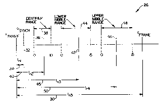
- FIG. 2 is a schematic diagram of the protocol of RF
30 uplink 26 using the improved telemetry format. The
uplink uses a damped 175 kilohertz RF carrier which is
pulse position modulated, as described in detail below.
Shown at 30, the basic timing unit of the format is a
frame, having a duration of t~. It will be understood by
35 those skilled in the art, however, that the present
invention can be practiced using fixed-length frames
';,'.',t : . . . - : ~'
,: ,. , , . ' :
,: . - , ', ' ' '-. ' : '.
:, ' . ~ .
''~ . ' : :
~..... ' "': . ' : .
' , ' '
2~7~3~
WO9t/10471 PCT/US91/~ ~9
--6--
having periods of shorter or longer duration. In the
preferred embodiment, the main timing source of
implantable pulse generator lO comprises a standard
32.768 kilohertz crystal clocX which provides a basic
5 clock cycle of 30.52 microseconds. Thus, a frame
comprised of 64 clock cycles and extending over a fixed
time interval of l.953125 milliseconds is a convenient
frame period, since such frame period is a binary
multiple of the basic clock cycle.
A unique synchronizing signal is positioned within a
first fixed range of each frame 30. This signal
comprises a synchronizing RF pulse 32 which is located at
a time tn1 within frame 30. To properly function as a
synchronizing pulse, it must be located at a fixed point
l5 within the first fixed range of frame 30, as shown at 34. ;
A four-bit frame identifier code is positioned
j within a second fixed range of each frame 30, such second
fixed range comprising an identifier range 38.
Identifier range 38 uses a total of eleven basic clock
20 cycles as shown. This identifier code comprises an
identifier RF pulse 36 which is pulse position modulated
within the identifier range 38. The position of
identifier pulse 36 within identifier range 38 identifies
the nature or type of data found within each frame 30 ?
; 25 which is being transmitted, such as peak sense, peak
pressure, sense threshold and others, as described in
further detail below. Shown at 40, time interval t~ thus
uniquely represents the value of identifier pulse 36,
which value in turn identifies the data type being
30 transmitted within frame 30.
Each frame 30 transfers one eight-bit byte of data
along with the identifier code. This data is divided
into two portions comprised of four bits of data each. A
first portion of this data, namely the four least
35 significant bits of the data byte, is positioned within a
third fixed range of frame 30, such third fixed range
' - ' ',-: ~ ' ' -` ' ''':
;:,: . . - . :
, : ~. - , ' ': :
f,j ~ ~ . . . . .
:;;": , , ; '. ~ .
,, , , - .
20~0~3`~
WO91/1~71 PCT/US91/OO~W
comprising a lower nibble range 44. A second portion of
this data, namely the four most significant bits of the
data byte, is positioned within a fourth fixed range of
frame 30, such fourth fixed range comprising an upper
5 nibble range 48.
A lower nibble pulse 42 is pulse position modulated
within lower nibble range 44, such that its value is
uniquely identified by its location, such as at a time t~
shown at 45. An upper nibble pulse 46 is also pulse
lO position modulated within upper nibble range 48, such
that its value is uniquely identified by its location,
such as at a time t~ shown at 50. Lower nibble range 44
and upper nibble range 48 each comprise sixteen basic
clock cycles, permitting each of the sixteen unique
15 values of the four-bit nibble to be specified. To
prevent data overlap, suitable guardbands are positioned
between each of the ranges within the frame to uniquely
identify the synchronizing pulses, thereby avoiding
undefined and erroneous data transmission.
FIG. 3 is a diagram of two frames of RF uplink 26,
wherein a first frame corresponds to Word l shown at 70,
and a second frame corresponds to Word 2 shown at 72. A
count of clock cycles is indicated along an upper
horizontal axis of this diagram for each frame. Each
25 basic clock cycle has a duration of 30.52 microseconds.
The first frame at 70 is initiated by an ~F pulse 52. A
synchronizing RF pulse 54 is shown uniquely identified as
precisely four clock cycles later. Because~the
guardbands are all greater than four clock cycles, no
30 combination of a frame identifier and data can appear as
a synchronizing pulse. Synchronizing pulse 54 is used to
provide frame synchronization between the transmitter
(i.e., implantable pulse generator lO) and the receiver
- (i.e., programmer 20).
An identifier RF pulse 56 is located within
identifier range 38, which range is defined as nine to
',~,"',,' ' , ;, ' ` '
~t ,. . , : , -
~J ' , . : :
,f,;,." . ~
.~.,',; .-, ' .
W091/10471 2~a43~ PCT/US91/00309
nineteen basic clock cycles from the beginning of frame
70. In Word l, for example, identifier pulse 56 is
located at clock cycle nineteen. This identifies the
frame as a particular type of data transfer, namely,
5 "Sense Threshold" as indicated in Table l below.
TABLE l
.
Position Identification
9 Memory
Idle
ll EGM-l
12 Markers . -
13 Peak Sense
14 Pressure Waveform
Peak dp/dt
16 Peak Pressure
17 Delta Capacitor Voltage ?
18 Activity Counts
l9 Sense Threshold
A lower nibble RF pulse 58 is located within lower
nibble range 44, which range is defined as twenty-four to
thirty-nine basic clock cycles from the beginning of
frame 70. In Word l, for example, lower nibble pulse 58
25 is located at clock cycle thirty-one, specifying a binary
value of seven on a scale of zero to fifteen. An upper
nibble RF pulse 60 is located at clock cycle fifty-eight
within upper nibble range 48, which range is defined as
forty-four to fifty-nine basic clock cycles from the
30 beginning of frame 70, and is demodulated in similar
fashion.
FIG. 4 is a block diagram of that portion of
implantable pulse generator lO which is associated with
formatting and transmission of RF uplink 26. Most of the
~:. . . .
,: , . , : : : . . .. .
'"' '; ', ,. ,, , : , '' .. ~ .
,: . . . - . , - ~ .
.
, . . ~ . .
;, ~,. ~ . , ~ .
,............... . . .
: . . -, .
y !
WO 91/lW71 2 a ~ 2 PCrlUS91/00309
unique hardware which embodies the present invention is
located on a single substrate, being a custom chip device
indicated generally by arrow 105. The remainder is
microprocessor-based logic indicated generally by arrow
5 lO0, comprising microprocessor 102, random access memory
(RAM) 104, and parallel bus 106. The function of
microprocessor-based logic 100 is described in further
detail below.
Chip 105 has an analog-to-digital (A/D) converter
10 108 which receives a number of analog inputs 110 from a
multiplexer (not shown). A/D converter 108 permits data
to be transferred~ via RF uplink 26 to be digitized as
necessary, so that all data is transmitted in a
standardized digital form.
Circuitry (CRC) for generating and analyzing the
cyclic redundancy code used to forward error detect
telemetry data transmitted over RF uplink 26 is indicated
~, at 112. In the preferred embodiment, it is also used for
data received by implantaDle pulse generator 10 via a
20 downlink (not shown). Circuitry (DMA) for providing
direct memory access to RAM 104 is indicated at 114, thus
~ permitting multiple byte transfers without constant
!~ management by microprocessor 102.
Key hardware used to implement RF uplink 26
25 comprises telemetry control and data buffer circuitry
indicated generally within dashed lines at 121, which
circuitry includes data buffer 116 and telemetry control
120, and up-link timing circuitry 118. Data buffer 116
includes storage for twelve bits of data. This storage
30 is partitioned into a four-bit section 119 for storage of
the frame identifier code, and an eight-bit section 117
for storage of the lower nibble and upper nibble of a
ç frame. Data buffer 116 thus stores all of the variables
for one complete frame. Data buffer 116 is used to stage
35 the variables for the frame which may be received from
: .~ , . ..
'' , -
. , ~ , .
,
, . . ;
., .
WO9l/1~71 2 0 7 ~ ~ 3 2 PCT/US91/~
--10--
RAM 104, A/D converter 108, CRC 112, or elsewhere along
parallel bus 106.
Telemetry control 120 consists primarily of a
telemetry status register. This register stores the
5 telemetry commands and status as loaded by microprocessor
102. The contents of the register are thus used to gate
the data at the proper time of the defined protocol.
Up-link timing 118 decodes the twelve bits of data
stored in data buffer 116 to produce a set of timing
10 signals which key bursts of RF energy at the appropriate
times to pulse position modulate the 175 kilohertz
carrier. Up-link timing 118 also keys bursts of RF
energy at the fixed positions within the frame
corresponding to the frame-initiating pulse and the
15 synchronizing pulse.
FIG. 5 is a basic flowchart showing the overall
function of the microprocessor-based logic 100. The role
is essentially one of initiation of the transfer, rather ~ .
than management of each detail of the transmission.
20 Software associated with RF uplink 26 is started at
element 130, usually by a down-linked command to transfer
data. ~ -
Element 132 schedules the requested transmission via
the up-link facilities. This scheduling prioritizes
25 uplink transmission requests. Lower priority is given to
continuous real time transfers, such as EGM and battery
voltage, whereas higher priority is given to single
occurrence transmissions of status information.
After scheduling, element 134 determines whether an
30 uplink transmission is currently in progress. If an
uplink transmission is in progress, element 132 re-
schedules the request.
If an uplink transmission is not in progress after
scheduling, element 136 initiates the uplink transmission
35 by activating telemetry control 120. Exit is via element
138. While some additional management of the process is ~;
.' '-.:
1,,~,", .",,
~'' i ' " .: ~ ' '. ' . . '
23~ ~32
W091/10471 PCT/US91/~309
required during the transmission, a description of such
further details has been omitted, since it is not
believed necessary to one skilled in the art to fully
understand the present invention. As to the software
5 associated with the uplink transmission, however, a
source code listing of the pertinent sections of such
software has been attached hereto as Appendix A, and is
incorporated by reference herein.
FIG. 6 is a block diagram showing the major data and
10 control signals of telemetry control and data buffer 121
(which includes data buffer 116 and telemetry control 120
shown in FIG. 4), and also of up-link timing 118. A
primary function of data buffer 116, as indicated above,
is the staging of the twelve variable bits of a given
15 frame which correspond to a four-bit frame identifier ID,
and dual-nibble data comprising a four-bit lower nibble
LN and a four-bit upper nibble UN. The data is received
over an eight-bit, parallel bus 159 and can be from any
one of several sources. Control lines E~MDATA at 150,
20 PRSDATA at 151, DLDMA at 153, DMADS at 155, LDANDAT at
156, ENCRC at 161 and LDCRC at 171 specify the source.
The output of A/D converter 108 of FIG. 4 is presented
separately to data buffer 116 as an eight-bit parallel
transfer to ADC(0-7) at 154 (see FIG. 6). The output of
25 CRC 112 is presented separately to data buffer 116 as an
eight-bit parallel transfer to CRC(0-7) at 160, since
those devices are located on the same substrate.
Telemetry control 120 outputs a number of control
signals, including EGMGAIN at 162, RVPGAIN at 163,
30 EGMTELEN at 164, ANULON at 165, RAMULON at 166, MEMEN at
167, PRSTELEN at 168, HDRCRCEN at ~69 and EGMNPRS at 170.
These control output~ re used to enable and control
inputs to data buffer 116. The key outputs of telemetry
control and data buffer 121 are TELRST at 182, which
3S resets up-link timing 118 and initiates the beginning of
a frame, and a parallel data transfer at 184, which
~,' ' ' ~.
.',` ;' ` ` ' ~ ':"
,~- . .
2~ 3~ -
WO91/10471 PCT/US91/~W
-12-
transfers the frame identifier ID, lower nibble LN and
upper nibble UN to up-link timing 118.
Up-link timing 118 receives the frame-initiating
control signal TELRST at 182 and the parallel data
5 transfer (ID, LN and ~N) at 184. A primary function of ?
up-link timing 118 is to key the transmission of 175
kilohertz RF energy at the proper times to indicate start
of rrame, frame synchronization, frame identifier, lower
nibble and upper nibble. Timing for this function is
10 provided by the 32.768 kilohertz crystal clock to up-
link timing 118 with clock signal XTAL at 186. An output
TELCLK is provided at 188 which keys the actual burst of
RF carrier at the proper times.
FIG. 7 is a block diagram of up-link timing 118. A
15 frame timing generator 202 provides the desired timing
for a frame according to clock input XTAL at 186, in a
manner hereinabove explained. Thus, each frame is
comprised of sixty-four basic clock cycles. The process
is initiated by receipt of the frame-initiating control
20 signal TELRST at 182, which enables uplink when in a low
state and disables uplink when in a high state. The
initial clock cycle of a frame contains a burst of RF
energy which is keyed by control signal TELCLK at 188,
which is also used to trigger the start of the data
25 decoding by an uplink word multiplexer 200.
After the proper four-bit quantity is selected -:
(i.e., frame identifier ID first, lower nibble ~N next,
; and upper nibble UN last), a telemetry pulse timer 204 -
determines the appropriate timing for a burst to be
30 provided to frame timing generator 202, and a
corresponding burst of RF energy is keyed. Each of the -
four-bit quantities thus results in the keying of a burst
of RF energy at the appropriate time within each frame.
FIG. 8 is a circuit diagram for the drive circuit
35 for generating the RF carrier. A control signal TELCLK
at 188 provides the timing information for keying the
i~ .
.
$::: : : .: :; ~ -~
:,, ,. . ~ ,: . . - . . .:- . . . . . .
., - . -' . , .. - :,. ., :, ,- .. .. . :,: .
:~' ~ , .
, ~ ., , . . : `
;~ . . - . .
:s, . ' ..
.~.i:. ... . .. . . . .
,",.
2 ~ 3 2
WO91/10471 PCT1US91/00309
carrier. A non-overlap generator 220 functions as a
delay device to save current by preventing output
transistors 230 and 232 from conducting simultaneously.
Every transition of control signal TELCLK at 188 causes
5 one transition by non-overlap generator 220. Inverters
222, 224, 226 and 228 are scaled to provide efficient
switching with sufficient drive to the gates of
transistors 230 and 232. Transistors 230 and 232 drive
the signal off of chip 105 to ANTDR at 234 to an antenna
lO circuit. A tuned circuit of discreet components,
capacitor 236 and coil 238, are located external to chip
lO5. Each transition thus causes this tuned circuit to
resonate at 175 kilohertz, thereby generating one uplink
burst.
While the invention has been described above in
connection with the particular embodiments and examples,
one skilled in the art will appreciate that the invention
is not necessarily so limited. It will thus be
understood that numerous other embodiments, examples,
20 uses and modifications of and departures from the
teaching disclosed may be made as to various other
systems for telemetering data to and from an implantable
medical device, without departing from the scope of the
present invention as claimed herein.
.-.. -- - , .
",
:, :
2~ 3~ .
WO 91/10471 PCTIUS91/00309
--14--
APPENDIX A
. . . ~ ......... . . ..
, rr, ;,
'':' . '- ' ' . , ' ' :
. ~ .
'~r. :'' . , :
~''" ' .
V~'.' " ' - : ' :
;'':',, . ' : , ''
'':' ; ,
' :
28~ 32
WO 91/10471 PCr/US91/00309
--15--
Avocet 6605 Asse~ler v2 20 ~01002 Chip~1-6AOS 10/12~89 Ot ~1 23
--------- R2 srsTE~ DATA AREA -~ ------- r i le: DATA AS~ 9
SR vision 3 0 S ------------ 7
S 400 eJt tlm rcsive Er~u S ;E~tenrJed telemetry Is c~ive
0006 401 ~9 st~te EOU 6 ;l~gnet stste ~de end rete sre
402 ;-et to lrOo i~COE rd ~o r~t~ ~ollo~dng
0007 404 rr trsns EOU 7 jperm nent proor~ino;
~05
OOtO 406 TLII ~IO~jl'.AG 1/5~: EW 10110000a tesi~ to clesr sll tele~etry
407 flegs e~ce~pt those eswcisted
400 uith e~tended telemetry
' 09
~10 .--.......................... -.. ----.. -
"' ;- tlm2 fl~gs
413 ;~erm_orog vslid EOU O ;Velid Permcnent prooremning
"~ occurrerJ
0001 415 teset Inhibit Eou 1 iReset inhibit te-tured
416 ; used In v~lld te messege
0002 ~17 reset_p~ce trigger EOU 2 Reset p ce trioger testured
418 - used in vslici te mess-ge
~0003 419 j~ sense rqs~ EOU 3 iSin9le Pe~E ense meesuremen~
~20 requested trom proorunmer
OOK 421 ~Inr cn1rm EW 4 Upllni confirmetion required
422 on ne~ even~
~23
~2~
425 ---------------------------------------------------------------------.
426 j- ULID
0005 420 éRC error EOU 5 CRC error indic~tor
OOOo 429 upl~nl_memory EOU o6 jUplinl~ Inclucie memory blocl~
000~ UO uplin~-cRc EOU 7 ;Uplini~ includes c2e nd h-~der
~31
~32
~33 .--.... --.. -------------------------------.. --.---.. ---.. ---.. -
434 j- Uplini~_fl~gs
.-.--.. --... -.-.. -.-
~30
0000 437 uplni disebleci EoU O Uplin~ is dissbled
0001 438 uplin~ bsr EOU 1 Uplin~ chsnnel is busy
0002 439 up r~m pnd EOU 2 jRAti uplinl~ pendino
0003 440 up tt~t_prd EOU 3
000~ 441 inSrtt pnd EOU 4 ;Interrog~te d~ts uplinL pending
0005 442 Ic~p!ri~r_pnci EOU S ;Loss ot c-pture merjer uplin~
~ 3 pend i ng
0006 444 mri~r_prd Eou 6 Even~ marl~er upl ini~ pending
0007 L45 me~s_prd EOU 7 ~eesured velue uplini ;oending
~6
0003 U7 UPLlil_Cli_SET EOU ~21^uplni disebled 21^uplini~ bsy)
448 Dis~ble uplinL snd se~ busy
~9 tor oein ot sion l
~50 ;--.. -... -.. ---.. -.. -.. ............... --.-.. ---
~51 ;- Upl inl~ sts~ ~tes
~52
j-------.---.------------------------.--....---------------------------
~5
000~ ~55 p oeO urlte EoU 4 ;Urite occured on p oe O
0005 456 IHgne~ swlied EW 5 Reec s~ltch \s closeci
0006 457 checiuum ~rror EOU 6 ;R m eheciuum ertor tleo
0007 ~58 POR oceured EOU 7 9~R tl-9
.ooro 460 UPLIII~_CLI~ iSI EOU 11110000B Clesr error blts In upllnl~
61 ~t~t
OOCO ~62 UPLli~_POR_llS~ EW llooooooa ;Init m st used during POR
~63
~64 ;------------------------------------------------------------
~65 ;
466 ;- Do~lnl inl~ Control Eyte qustes
~6~ ;
.. , . - , , . ,. :, ' . ' " ' ' '
.. . . ,: . ' ~ : :
' : :: : :
r ' ' ~ . . .
; ' .- ,, . ' :
.':"' ' ' ' .: ' ' .
~j ' . '
'' , ': '
~: ~ ',, : , .
: :~ " : . . : . . .
: ' '' '' .... .... ..
2~7~132
W O 91/10471 P(~r/U S91/00309
- 16 -
Avocet 61805 Asse~l r v2 20 ~01002 Chip-106805 10/12/89 08 11 23
- R2 SlSTEt DAIA AREA ~ -- File: DAlA ASti Psgc lZ
...------ SR~vision 3 0 S z-s------s--
~04 ;-.. -.. -.. --
L95 -
~96 ;- Ielemetry eclu-~ s
~97 -
~,99 -... -... --...... ----....... .---............. -
~99
500 ;-----.. ---.--.. ---------.. ------........... --.. -
501 ;- tierLer v~lues
s02 ----~-----------------------------~--.................................
503
0066 SOO ~1 REf2AC SERSE EQU 66H Ventricsl retrsctory sense ml er
OOEE 505 llr 5~15E Eou OEEH jVentricsl sensc rl~rker
OOCC 506 t~ PlCE EOU OCCH Ventric~l pece merker
0077 507 ~It LOC EW 77H ;~oss o~ cspture m rker
OODD SW l~_IRIGGERED EOU ODDH ;TrigterecJ p ce m rker
509
0080 510 UP C2C ECU ~OH ;Uplin~ CRC vrl ~or ULID regisz
0000 Sli UP ROCRC Eou o Uplink no CRC vel tor ULID re5
OOLO 512 UP tEt EOU ~OH jUplink mem vrl for ULID regist
0000 513 UP RCllE~ EOU O ;Uplink no mem vel tor ULID
;regis~er
515
516
517 ; ID cocle encl C2C bits tor uplink messeges
518
sOD80 519 STATUS ID EW O UP CRC UP RC~Et ;Contirm~tion ID
OOCO 520 2A~ ID Eou O uP C2C ~ UP tiEt ;RA~ uplink 10 ~ `
0003 521 llAR~E2 ID EOU 3 ~ UP ROCilC UP tiEti ;tierker chennel ID ~ `
00~ 522 Pl;SERSE ID Eou ~ UP IIOCRC UP iEti ;tieesure velue IDs
OOL6 523 PI~DPDT ID EOU 6 UP IIOCRC ~ UP iEt
00~7 52~ PltPRESS ID EOU 7 UP HOCRC ~ UP tiEI~
OUJ 525 DLT~VOLT ID EOU 8 uP IIOCRC UP tiEti
00'9 526 ACTCRI ID EOU 9 UP tOCRC UP ItEt
OOLA 527 SERSIHRS ID EOU 10 UP_RiOC2C UP iEti -
528
529
530 ;........ -........ --
531 ;- ~isc. telemetry ec~etes
532 ;---------------------.--..............................................
OOC3 53; AC ESS CCOE EOU OC3H ;Teleme:ry sccess code tor IPG
OOE3 535 R~ I~ODEL ID EOU 101100113 ;IPG model l.D velue mc~del 8 L~
0027 537 IRIRRC 512 EW 39 Si;te ot interro~ste block
OOJO 538 HAX tE~READ EW 128 jtcximum memory blocR recd size
539
ooor sLo PGO EOU OFH ,Control byte Pege O ID
0001 S~l PG7 Eou 1 Control byte Per,e 7 ID
0002 502 PG8 EW 2 ;Control cbyte Pege 8 ID
000' 5~3 Pe10 EW ~ ;Control br~e Pege 10 ID
SL~ :
0003 S~S DRL~ EXTRA LER EW 3 ;tessege overheed tsut~ trom
5~6 IIv bytcount~
0001 5~7 DllLtt CS IRDX EW 1 ;First vsl tield In do~mlinR
5~J ~ ~ ;messege
SL9
550 ; Emergencr vslues
551
00~1 552 É~C_Pv Ew ~1H ;Emeroency Pulse Uidth 12msl
0018 553 EYG A)iP EW 16H ;Emer9ency pulse enplitude 55~ ;16.0 Yo~ts)
555
0023 556 HIGH xATE EOU 23H ,Highest rste ths~ uJll sllo~
557 ,tull IU~ uplink t170ppm)
001E 558 UPLlRlt DELA~ Eou lEh ;l~inimun time betore n xt
559 ;scheduled event
560 needed tor RAX uplinx 1300ms)
0003 561 UPST~T DELA~ EOU 03H llinim~m time be~ore next
s' ~ -: . . . -: : . ~ ,
~,:,- . '.,. ,' ~ : ' .: .
'~ ::. :' . . , ~ ,. ' '
: .... , , , -
,
,~,: ':
207~132
W O 91/10471 P{~rtU S91/00309
- 17 -
Avoctt e;805 Assenbl~r v2 20, ~01002 Chip-1~b805 10H12/e9 08 12 32
---5 R2 EXECUTIVE 5-~ 55~ = file POREXEC lS~I P~ge a
-------- SRevision 3 0 S --r----s=
265 ;- POR snd E~ecutivt ~scros
266 ---------------------------------------------------------.-----
267
8 5---------------------- CHEC~ tlAl~ER_UPLlB~
269 ~-
270 jP Deterrline ~hlch r~rEer cocle to uplinE uhile in llugnes mocle or
271 ;9- e~tenried teler~etry l~ uplinl: is in progresS, the m r~er
272 ;5 uill be igonred
2n ;~-
27~ :~ ERTRT CC~DITIONS
275 5- A p~ce~sense or refrectory sensed even~ is ceing processed
276 ~- PACESTAT indicetes it the event ues refrectory
277 ~-
278 j5- EXIT CCIRDITIClRS
279 5- If moLer chrnrel i- ective end e velid msr~er is detecterJ;
280 5- s r~rLer is uplinl~ed
281 ~-
282 5-----------~----------------------...................................
283
28~ ------- .. ............... ..
285 ,5 ~ACRO CHEC~ I~AR~ER UFLIN~
286 5 BEGIN
287j9 ~- chec~ for m rLer uplinE )
288 a IF (ruri~ers ective of rug flsgs) THEN
289 u EEGIR
290 -
291 ;CHEC~ I~AR~ER UPLIR~ ~ACRO
292 ;CtlU START
293 ;Jump if r,urLer chennel ROT sctive
29~ ; BRCLR rr rLers ctive,rd g_fl~gs,C~U_EllD
295; ---- --- ----. ...... ............................
296; 5 IF tt~tf~ctorr evnt ot PACESTAT~
297;;5 ARD ~sensed evnt ot eJ~ec tlegs)~ THEN
298;;5 BEGIR t- Retr~ctory sensed event )
299; D IF ~timeou~ t event time~ > 1~ 7HEN
- 300;;~ REFRAC_SERSE;
301:;a ELSE
302;;~ EXIT;
- 303; 5 E\ID
, 30~ .. ........... . . .......................... ............ .
305 Junp it ROT refractory sensed even~
306 BRCLR refrectory evnt,PACESTAT,C~U WT
307 BRCLR sensed evnt,e~ec fl-gs,C~U WT
308 LDA timeout int
309 SU3 e~ent t~re
310 aP ~1 ;Is there enough time for msrler uplinR?
311 BLS C~U ERD ; llo, just e~it
312 ; LDX 1~ REFRAC SERSE
313 ; SRA C~U UL ; Tes, loed m r~er sr~ 9O wl;nE it
31~, . . . .. .. ...... ~ .. .... . . . . . ... .
315j j5 ELSE IF ttpeced evnt of ~c tlecs) AN0
3lo6;;5 tsensed evnt of e~ec flegs)l 7HEN
317 ;;5 SEGIR
318 ; 5 t- WT ~ode, It tri;gered event send e triggered m rRer,
319 ;;5 unless output is inhibited then sencl sense rurLer l
320;; ~
321 ;;~ IF 110Ttlnhibit of tlm tlsgs1 THEN
322 ;;9 ~ TRICGERED;
323 ; 5 ELSE
32~ ;j5 ~ SERSE
325 ;;5 ERD
327 ;C~U WT
32O ;Jurrp if 11OT both p ce srd sense
329 BRCLR peced evnt,eJ ec l-gs,CltU C~PACE
330 ; SRCL1 sensed evnt,el~ec tlegs~cl~u C~PACE
331 ; ;Checl~ 1Or output irhibited
... . . . .
.' ', '; ' ` ' " , '~
~." ' ' ' ' .' . . .
.~.'i''. '
. ~'.', ' . . '
,~
.. . .
',,"
WO 91/10471 2 3 7 ~ l13 ~ PCr/US91/00309
Avocet o805 Assenbler v2 20, tO1002 Chip~lL6805 10/12~89 08 12 32
~-------- 112 ExECUTlvE ~---------~-~-------- File POREXEC ASil
--------- SH~vi~ion 3 0 S ---------
332 ; BRCL2 Inh(bit e~bled,tlm tlegs CiU IIIHBT
333 ; LDX t~ SEllsE I f not, gét sense merk r
33L ; 8RA CilU_UL jCo ~plink it
335 ;C)IU INHBT
336 ; LDX ~ TIIICCERED ;Elct get trlgoered m rker
337 ; ~RA O'U UL ;And sencl 1
330 ;; _
339 ;;~ ELSE IF ~Ipeced ~nt of exec tl~9s1
3LO ;;' ~ID ~)lo~lnhlbit ot tlm tleos~)) THEN
3Ll ; ~ ~- It e~cing Is not inhlblted, semd e PACE ~rl~er )3L2 ;;' ~ - ~11 P~CE;
3L3 , - --- -----
3LL iC~u C~PACE
3LS ; ;Ju7~p 11 ~IOT e cecl or If inhibitecl
3L6 ; B2CLi peced evnt,exec flegs,C~U C~SEI/SE
3~7 ; BRSET inhib~t en bled,tlm flegs,CtlU C~SEI~SE
3Lô ; LDX t~ PACE ;Else 9r~ m rker code
3L9 , 8RI C~U UL ,~nd stnd it
350 ----------------------------....................... :
351 "~ ELSE IF ~sensed evnt of exec fl~gs~ THEI
352 ; ;~ x - tll SEIISE;
353 ;;~ ELSE
35L ;;i~ ~- Ilo m rker ~o uplink exit m cro ~
355 ;;~ EXIT;
357 ;CIIU_CI~SEIISE ~ -
358 ; ;Jump it not sensed event359 , DRCLR sensed r~nt,exec tlsgs,C~lU EIID
360 LDX Llll SEl~sE ;Else get m rker velue
361 , - ------------------------ - ------
362 ,,~ 1- Uplinl: ~rller eo~e ~ -
363 ;;0 CALLII UPLIIIS ~ARsER~x);
3~L ;;~ END; ~- ~r~er ch-nnel ectiw )
365 ;;~
30,6 ;;---- --- -- - -- -- - - ----- - - ---
367 ;C~U UL
36a ; UPLllil_~A2~E2 ;Ulink m~rker ~v-lu- in x~
309 ;C\IU_EUD
370 ; SEIID~
371
372 ;~ EIID; (- CHECI~_tlARltER_UPLI1111 )
3n ;----- - - - -----
37L
375 SEJECT
~"':'"' ' '.. ~ : - ,
. .
~' . . . : :
,. ~ :. ' .
.... . .
''~' ' ' . ... ;
;.: . ' ' -:
,............................... .
,~,,~ . , .
2 ~ 3 2
WO 91/10471 PCr/US91/00309
--19--
Avoctt 6~05 Asselrbler v2 20 ~01002 Chip 1~6O05 10/12/89 08 12 32
22 ExECUtlVE -~ ------- Filc POAEXEC AS~ Psge 12
SRevision 3 0 S -----~
~ ~ ------------ UPLIN~ IIA2~E2 -----------------.---
~.J1 ;'
'82;P This ~cro upllnEs event ~rHers if the chsr~el i~ free
i ;P
~4 ;P ENTRr COllDlTlOliS
'JS P This routine eJ~pects ~ to contein the ~r~er vrlue to be
U6 P 41inHed
~o~
'oo ;P EXIT COiDITIONS
'ô9 ;P If the uplinl~ thsnnel Is svsileble It is csptured srld the
90 ;~ Hr~er Is uplin~ed If the chennel is tJsy end there re
~91 ;3 no pe~iing merLers the ~rl~er is tlegged pencling for uplin~
~92 ;P st the erd of the current upl inL
~93 ; 9-
~ff
~96 ;UPLIN~ ~AR~ER SIUCR0
'97
;......................................................................
499 ;;~ ~ACRO UPLINII ~IAR~E2;
5009 SEGIN
501,9 d;ssble interrupts
502~ I- Chec~ if uplink chennel is svsilsble )
503;;~ IF liO7tuplnlt dissbled of uplinE_flegs~ T~EN
50~, ~ 8E t I N
505; ~ IF NOT~uplinR bsy of uplin~ tlsgs~ ThEN
506, ~ SEGI~
507~ t- It Uplinl~ chennel is tree then uplinl ~rRer ~
508; ~ uplinL bsy of 41in~_tlcgs - 7AUE;
509;;0 eruble ~nterr4ts
510; ;~ ~rlter v~ Jj;
511;;~ TELADNI :- NlA0DRt~ri~er_v-l);
512;;O 1EUDLO :- LOADDA~ri~-r_v-l);
5~3;;~ 8rTCOUNT :- 1;
51~ ULID :- IIAA~ER ID;
515;;~ R~l uplinl~ of TELSTAT :- TRUE;
516;;9 END;
517;;................................................. ..
51O ;UPh START
519 SEI ;Dissble interrupts
520 ; ;JUTP i1 uplinl~ dissbied
521 ; 8RSET 4inl~ dis~bleci uplinR ti~gs UPLllDON
522 ;UPLNARI ER
523 ;Jurp If 411nH wsr
52~ ; 5RSET 41inl~ bsy uplin~ ti~gs uP~_9sr
525
526 ; Upl inE NOT busy
527 ;;
52c ; ;Fleg 41in~ tusy
529 ; SSET 411nlt_bsy uplinL_tlegs
530 ; CLI ;Eneble interr4~s
511 STX IHrl~er vel ;Put mul~er velue In icut1er
532 ; LDA 6HIGH ~rL~r_vel ;Cet hSS ot butfer ~dress
S33 STA TELAOHI ;Uurite it to herchere
53~ ; LDA ~LOU ~Ler_vel ;Cet LSS of eJtter Klciress
535 ; STA TELADLO ;Etc
536 ;
537 ; LDA ~1 ; Cet output eount
53O ; STA SrTC~iT ;~lrite to hsrdvsre count register
S39
5'0 LDA ~iAll~ER ID ;Cet ID eocl-
5'1 ; STA ULID ;T~I I the hsrdusre
5~2 ; ;Stert the 41in~
5~3 ; 95ET IA~I uptinl~ TELSTAT
5~ L UIA upL~DoNE
5~5 ;;......................................................................
5~6 ; ;~ ELSE
5'' ;;~ ECIN
;
__,; .... .. .
s~
;, , . :i. ' , . ~.:;
:. ~ - . - ,: , , . -
~.;.' , : , ; :
': .
.~.. : . . ' . . .
WO 91/10471 2 ~ ~ ~d ~ 3 ~ pcr/us91/oo3o9
--20--
Avoc~t ooOS Assen~ler v2 20, ~`01002 chip 1~05 10~12/E9 06 12 32
112 EXECUTlvE ~ r~D-~ file POREXEC.AS~ P~9~ 13
SP~vision: 3 0 S ~--------
5~E ;;~ (- lf no ~rlt~rs sre p~dlng the tl-9 t~e pc~ing )
5~9 ;;~ mrl~r_~ of uplln~ tl-gs :- IRUE;
550 ;;~ ~tl~er v-l :~
551 ;;~ E~ID
552 ; ~ EllO
55~ " ;i
555 . . . .
556 jj Uplinl~ wsr
557 ;;
55E ;UPL 95~
559 ; BSET ntltr_Fr~,uplinL tl~gs ;FI-g morl~er petding nrJ
560 , STX ~r~er vel store m rl~r in the but~et
562 ;UPLYDOliE
563 , ~LEIID~ ;Er~ble interrupts
565 --- - - - - .
566 ja EIID; (- UPLlll~ lu2~EP )
567 ; -- - --.--.---
s6a
569 SEJECT
i.~
~,i,';,, '',', ' ' ', ' . , .i
~;'' . ~ ~ . . .' , . - : ,
'` ~ ' ' ' , . : , ,
'''' ' ' ' ' - . ' .: ,' ,`- ' : . .''
:: . . - . . ,
1:~. ,
~ u ~
W O 91/10471 ` PC~rlU S91/lUD3U~9
--,1--
Avocet eJ05 Asle~bler v2 20 ~01002 Chlp l-UOS 10/12~89 08 17 07
-- R2 PACE OR SENSE ~ODULE ------------- Flle POS AS~ a9
--------- ~Revision 3 0 S ----------~-
.
;' -------- UPLIN~ INTRRG ------------.-
le~l7
1618 3 This mecro upl inks thc interrogete blrc} of si2e INTRRG 512 snd
1819 ~ starting st thc eddress pointed to by INT2RG AD It the uplink
1U0 3 chsrnel is tree Other~ise lt there Is no RA~ upllnk the
lô21 P interrogete block is set pénding snd It seheduled vie the ne~t
le22j3 TELitF interrupt occurring uhen the upllnk chennel becomes
1U3 ;3 tree All other uplin8- hsve to be dissbled l~hile checking the
1824 ;P uplink tlsgs to svoid contentlon o~ the uPlink channel
le~25 ~-
lU6 P ElitRT COIlDlTlONS
1827j3- Ilone
1~20 ~-
1829 3- EXIT COIIDITIONS
1 e~O ~- None
le31 ~-
1~33
1835 ;3~C~O UPLIN~ INTRRG;
1836 ;~BEGIN
1~i7 3 E- Crpture uplink chennel - It busy set interroga~e perdin~ ) -le38 ;3 diseble interrupts;
18~9 3 I~ NOI~uplnk_disabled ot uplink_tlags) 7HE~
l U l UPL I IIY l NTRRG XIIACRO
18L2 SEI ;Dis--ble interrupts
1843 ItRSET uplnk_disebled uplink_tlegs Ul_END
1US 3 8ECIN
lUo j3 IF NOT~uplink bsy ot uplink_tl-9s) THEII
lU7 3 8ECtN
lU6 j3 uplink_bsr of u~link_f~-gs :- TRUE;
lU9 ~ en ble intertupts;
1350 ~ stetbrt - ue~lnk st~t;
lôSl ~ CJLLH LOAD lliTRRG UPLIN~ VITHIN R2LIB;
1852 O RA~ uplink ot TELSTAT - 7RUE;
1~53j . ENo;
es4 ------------.-----..................................................
1855 8RSET uplink bsy uplink tlr~s Ul UBST
1856 j 85ET uplinl~_bsr uplink_tl~95
1857 ; CLI ;Enrrle interrupts
lôS8 ; LDA uplnk stat
1859STA ststbrt ;Initiali2e the uplink status byte
l'~ iul Llu
1861 ; LOAD INTRRG UPLIN~
lU2 Ul LIU END
le63 ~SET RA~ uplink TELSTAT
le~4 j 8RA Ul_END
le65 ---- - - --- - --- - - -
le~6 3 ELSE
le~7;3 intrrg_~nd of uPIlnl~_flsgs - TRU;
1~43 END-
le~9 ,........ '
1~70 UI U85~
lô71 85ET intrrg_Fr~i uplink tls~s
n ';- ------ -- ------- ....--.......................................
n ;;~ en ble interrupts;
1O~4 ;;3
.;......................................................................
lô76 UI END
16~ CLI ;En ble interrupts
1~7E~ I END~
lei79 :...................................................................... .
lU10 ;3END; t- UPLIN~_INTRRG )
eJl .......................................................................
lU2
1e~3 SEJECT
:
.~
r;, - ., . . . . .'
'r~ I ' . '
;'.'' ' '. ,
~, , , . ~ ' , . : : '.
. ,,' ' ~ ~ ' .;'i ' . ':
t,~" . . . . .
~'~ ' '. ,.
WO 91/10471 2 0 7 ~ d 3 ;~ -22- PCr/Us91/00309
Avocet 6~05 Asselrbler v2 20 ~01002 Chip 1~6~05 10tl2/E9 0E 15 30
R2 LSCAP IllTERRUP1 lmuLE --~-------- rlle L0C AS~ P-;~0
--------- S~evisirn 3 0 s ------------
. .
~09 ;P''~ --------------- UPLI~ LCAP ~lAll~ER --------------------- -
~10 P - --
~11P This n~cro uplinlts ~osr of crptu-e mrrLers
.12 ~P
~13 ;P EliTRr COliDlTlOllS
~14 ;P Under me~ne~ opere~ions the LSCAPIIIT interrupt is ulteci for
~15 ;P the uplinlri ot LOC _rLtrs 1t the chennel is tree
' 16 ;~-
~ ;P EXIT COljDlTlOljS
~lB ;P lione
~19 p
20 , ~---------------- -------------------------------- ------.-
~21
~23 ~ ~ACRO UPLII~I: LCAP ~ARI ER~
~24 ~ SEGlli
~25
~26 j0 diseble interrt~ts
- ~27 ;D IF ~IOT (uplnlt dise~led of uplinlt flegs~ THE)I
~29 ;UPLlli~_LCAP_l~ARllER ~ACPO
~30;UL~ START
~31 ; SEI ;Disrble inserrupts
~32ULY I IIT
433 . Jump it li0T ~N0T uplnlt dis~blerJ)
U4 SRSET uplnL disrbled uplinlt tlegs UL11 DOIIE
~35
U7 ;;0 SECIIl
~38 ;;~ IE liOT~uplinlt_bsr ot 41init_tlsgs~ THEII - -
o
~Ju~p it uplinlt inu~y
~1 i 9RSET uplinlt_i y uplinlt_tlsgs UL~I_LCP
~2
~3 ;;......................................................................
~L~ ~D SEClll
~S ;0 i- It Uplinlt chennel Is tre- then uplinlt merker )
U6 0 uplinlt bsy ot uDlinE tlsgs - TRUE;
~7 0 en ble intertupt-;
"ô j j0 TELADHl :- HlAD0ltLCAP ~AR~E2~;
~9 ;;0 TELADL0 - L0ADDR~LCAP I~AA~ER);
~50 ;;L SrTCwNT - 1;
~51 ;;0 ULID - l~lARtER ID~
~52 ;0 RAI~ uplinlt Df TELSTAT :- TRUE;
~53 0 EliD
~5~ ............... '
~55 95ET uplinit bsy uplinL fl~gs
~56 CLI En jD'e interrupts
~57 LDA flHlCN lcsp merlter ;Ctt ddress I~S~
~5~ STA TELADHI ;Yrite to controller reoister
LS9
'60 ; LDA ~LW Icsp merlter ;Cet Kidress LSil
61 ; STA TELADLO ;Yri~e to controll-r
62 ; LDA ~1 ;Ctt ~te eo~nt t
63 ; S7A 9TTCOUi~T ;Yrite to controller
- 6~ ; LDA ~lARltER ID ;Cet ID
U5 ; ST~ ULID ;Yrite to eontroller
e;6 ; 05ET LUI uplinlt~TELsT~T ;Stsrt uplinl
U7 ; 0RA UL~_D011E ;Thsts sll folE~
~6~
~0 0 ELSE
71 ; 0 SECIII
;. ~n ;:o ~- It .,0 ~-L~ ndin9 the tlsg e~e p~nditg )
:; ~n ;:o Icsp mritr_~rd ot uplinlt tlegs - TlUE;
~r~ ; o EIID
~75 ;; o EIID;
.,, . ,. . ,. ~, , , . , ~: : . , ,. . , :
'~!' ,
' .: , ' . ' . ' . . ' , ' . , ,, ` '~
~;', ` ."'`' : :
`:~', ~ . ' ' ' : `
".':':. . ' ` '` , ~'' ; ' -
W O 91/10471 2 a ~ ~ ~ 3 ~ Pc~r/Us9~ D3uD9
- 2 3 -
Avoce~ U05 Assembler V2.20, ~01002 c~ip~1- U05 10~12/89 08:15:30
---- R2 LSCAP IIITERRUPT ~COULE ~-~S------~- File: LOC.ASI' P~te 11
S2 ev i s i on: 3.0 s ---~
~7 ;UL~ LC?
~78 ; ~Jump ~f ~p m~r~er Ptndir~s
79 ; ESET ksp mr~r_~d,uplinE tlr~s
ôO -- _
~1 .. ....... _
~82 ;,~ er~ble /nSerrl4t5;
~3 ........................................................................
~U ULII DC~E
~85 ; CLI ;En b~e inserrupts
~86
~7 ; S,E~D)/
~U
~9 ..... ..........................................................
~90 ;~
~91 ;~ EUD; ~- UPLI\I~ LCAP_llAR~E~ ') . -
92 ~ ~ :
~93 '......................................................................
~9~ -
~95 SEJEC7
., ,..
., - :
", ~
~, ' . ' ' .
'; :: : . . ! . . : ..
~ . ' ~ ~ ,` ' .
WO 9~ ~i71 2 ~ 3 2 PCr/US91/O~f3~f9
~voc~ e,aOS Asse~ler v2 20, ~1002 Ch~ oaOS
------ R2 ADC INTERRUPT ~OULE ------------- ti l AOC IS)~ 10~12~E9 Ot 1~ 30
--------- S2evision: 3 0 S ... ,.r.. ~9e o
1t8 ;- AOC Interruc~t tl-cros
~9 ;.. .......- -... -.. --.. -...... --.. -----.. --.-..................... -... -
190
191 ;P---------------------- UPLIU~ ~EAS VAL ----------------------------
192 ;'-
193 ;~ This m cro is used to uplink ~essured vslues
~9~
1ff ;~- ENTRT CONDITIONS
190 ;~- The srrsy ness vsl hss been lo~ded uith the 'W'P""'
197 ;~- d ts 10r uplin~ The dr of bytes for uplink is stored
198 ;~ in the x register.
199 ;--
200 ;~ EXIT COUDITIOUS
201 ;- It the uplinit chsnnel is tree It is c~ptured erd the d~r
202 ;9- in the mess_vsl bufter is upl;nled If the uplink hennel
203 ;~ is busy ~ith s IIA~ upllnk the ele~sured velues sre
20~ ;~- disc~rrkd Othervise if the ch~nnel Is busy the measured
205 ;0- vslues re fls9ged ss pe~ding snd uplinked on the nex~
206 ;2- TELSF interrupt
207 ; ;~-
20~ ;~--------------------------------------------------...................
209
21t ;~ liAC20 UtLlNI~ ~EAS VAL(x)
212 ;0 BEGIN
213 ;0 If UOT(uplnk_dissbled of uplink fl~gs) THEN
215 ;UPLIU~ ~IEAS VAL ~ACRO
216 ;L~V START
217 , ffRSET uplnk_dis-bled,uplink_flsgs,U~V_ENO
220 ;0 EClU
221 ;;~ IF UOT(uplink_bsy of uplini~ tlegs~ THEN
223 ; ;Junp if uplink busy
225 , IIRSET uplink_bsy,uplink fl-gs,U~V S~V
227 ;;0 EEGIU
22t ;;-' ~- Uplink cher~el free uplini messured vslue buffer
229 ;;0 uplink_bsy of uplink fl~gs :s TRUE
230 ;;~ TELADHI :- HlAODR~meis vel lO~ 1
231 ;;~ TELADLO :~ LOADOR(mees vellOl)
232 ;;~ B~TCOUNT :~ x
233 ;;0 ULIO :~ meos id;
235 ~ xAli_uplinl~ of TELSTAT :- TRUE; ,~
237 ; BSET uplink bsy,uplinl tlsos Set uplink busy
23t ; LDA ~HIGH me~s vsl Cet buffér ddress llSB
239 , STA TELAOHI jVrite DIIA ddrtss register
2-1 ; LDA ~LOV 0e-s vsl ;Cet bJff~r ddress LSB
2~2 ; STA TELADLO , -tc.
2~3 ; STX B~TCOUNT ~Urite byte count
2-~ ; LDA ~cs id ;C-t ID
2'5 ; STA ULiD ~lrit~ to h-rd~sre
2~6 ; BSET lAl'_upllnk,TELS;AT ;St-rt uplink
2~7 ; BRA Ul~_END ;CO tAit
2',ô
250 ;;0 ELSE ~- IiOT uplinl~ bsy )
251 ;;0 tEGlN
252 ;;~ ~- S~t ~ssurtd vslue uplinl~ pending )
253 ;;~ 0e-s count :~ A;
25~ ;;0 less_pnd o1 uplink_tlets :- TRUE;
255 ;;0 EUO
25o ;;0 EIID;
250
.,~,.. . . . .
.. . . . .
'~, ',;,'' : :
, - :
, ~: . - -
."'', ~ . .
2a~a~3S~
WO 91/10471 - 2 5- PCr/US91/00309
AVDCC~ ~OOS Asse~bler v2 20, S01002 Chip~1-UiOS 10/12/~9 0~ 9
--------- R2 ADC I~ITE2PUPT ~OOULE ~ File AOC AS~I Pe9e 7
--------- -2evision 3 0 S r-----~-~---
259 I~V S)tV
260 ; SIX ~ees cov~ ;S~ve penrJing byte cDun~
261 SEI ~ss_~rd,~llnk tlsgs ;Sho~ pending upling
262 j SIIA L~V_E)~D ,Ihsts ell toll~s
263 UI~V E~D
2D~ ; SEIIDU
205 ;-------~-------.. -.......................... .
266 ;~ E~ID, (- UPLI~ EAS VAL '~
207 , - --- ----------- --- -
20o
209 EJECI
"~ .. -.-, '. ' . ., . , . ' . : ' ,
'~-: . ' . . : - :
,' ' ;~ . -
,, ~ .
~r :, ' . '
t'~
wo 91/10471 -26- Pi~/US91/00309
Avocet 6805 Assembler v2 20 ~01002 Chlp146805 1/18~90 10 35 56
--------- R2 TELE~ETR~ I~OOULE ~ -- File TLH ASH P~g~ 7
--------- SRevision 3 3 S ------------
379 ;a- -
380;~- R2 Pecemaker Hodel 8444
381;a- HOOULE TLH
38Z;~-
383;~- The TLH ~wdule processes m gnet mod operetions ~hile she reed -
384;O- ~i~itch is clo~ed The~e fnclude the handling of the telemetry -
385 a- p-otocol, ~he THT end leed test ctlv-tion the puls- pressure -
386 ;0- c-lcul~ion tor lo~ ot e-pture m rkers detection The
387 ;0- teleme~ry pro~ocol invrlves proce~sing do~nlInk end uplink
388 ;a- messages Do~nlink messeges ere velideted before being ected
389 ;a- upon The uplink consists ot confirma~ion snd confirmation
390 ;a- -pli-s tO do nlink reques~s
391 ;a-
392 a- Routines defined in this module inclucie
393 'a
394 ;a- Macros
395 ;a- Do HEHURITE - transfer do~nlink r cord to
396 ;D- memory
397 ;a- EXEC SPEC FUNC - decode end execute special
398 ;a- function
399 ;a- EXEC SPEC REO - decode nd execute special
400 ;a- ~ ~ requests
401 a- PROCESS MEHURITE - ~r-nsfer dolnlink record to
402 ja- memory nd evaluate it
403 ;a- PROCESS HSG - decode memory offsets
404 ,a- SlJITCli TO NOH ~GHODE restore non magnet mocie
405 a- oper-tion
406 ja- VALID~TE_HSG - validate do~nlink message
407 ;a^
408 ;0- Procedures:
409 ; ~ None
410 ;P
411 ;a^ Drivers
412 ;~ GULSIN7_PROC - gain or loss interrupt handler
413 ;a RDS~lliT_PROC - reed-s~ ch in~errupt h-ndler j~
414 ;a- TELEFINT_PROC - telemetry icuffer in~errupt
415 ;a- handler
416 ;a-
418
419
420 DEFSEG TLH CLASS~COOE
421 SEG TLH
422
423 SSETLN~MACROS INC); XINCLUDE HACROS INC
._ . .,
, ~j, ~ . .. .
L,. .. . .
~ '' '"' " ." ' ,...... ' ,
.. . .
~" ' ''" ' ' ' ' ~' , .'''
,; " ' ' '
~ '
2~7~d~2
WO 91/10471 PCI-/US91/00309
--27--
~vocc~ 6805 Assemb~er v2.20, #01002 Chip~1468CS 1J18/90 10:35:56
--------- R2 TELE~ETR~ ~OOULE -~ File: TLII.A511 Psg~ --------~ SRevision: 3.3 S ~--n~-------
424
425 SUOALLPUBLIC
426 SSETLU~EOUATES.IUC~; XIUCLUDE "EOUATES.IUC"
.....
:: , . , :
;.' ' ,, ~, : '' " "' ~ ,' " ', '
. .
;
.~,~ . . . .
.~.~ , ;
2~A3~
WO 91/10471 PCl-~US91/00309
--28--
Avocet 6805 ~ssemoler v2.20, 401002thip~14 UOS 1~18/90 tO:35:56
R2 TELEI~ETRS t5XULE ~ File TL)~ 5~4 F~ge 33
--------- SRevision: 3.3 S --~
1813 ;^ Telemetry Subrou~ines
1815
1816 SEJECT
~, . -,
~:i:~: ' . - : ', :' :
~,'r~'., , . " '', ' , "' , '',~, ', "; ' - '
.:, . : , ~, .- , .. .
2~7~13~
wo 91/10471 PCr/US91/00309
--29--
Avocet o805 Assembl r vZ 20 z01002 Chip=146805 1/18/90 10 35 56
R2 TELEMETR~ MOOULE ==-~ -=- Fil- TLH ASH Page 1
52evision 3 3 S _===5==s--===
1818 - Telemetry Interrupt H~ndlers
1ô19 j.~.. ----... --------.. -----
1820 ;a---~ -- GUSLINT PROC ---~
1821 ;~-
1822 a~ This procedure is the gain/loss Interrupt h~nol r ~nd it is
1823 ;a- non-preemptive It is responsible for controlling the do~nlink
1O24 ;a- eno disabling uplink Uhether the interrupt is do to a gain or a
1825 ;a- loss of signal can be determined by reading a bit in the TELSTAT -
1826 ;a- egister. At the oeginning of dolnlink all penciing upllnks re
1827 ;a abandoned and the TELBF interrupt is m sked out until the end of
1828 ;a- dounlink In uhich case it is reenab~ed after being first
1829 ;a- cleared in the case of do~nlink overrun 0O~nlink is then
1830 ~a- disabled unti~ 3ust betore the uplink rcsponse either a status -
1831 ,a- uplink or e RAH uplink
1832 ;a-
1833 ,a- EN T RY COND Z T I ON S
1834 a- No other interrupts are enableo at this point ADC interrupts -
1835 ;a- ere the only higher priority and they are ignored during
1836 ,a~ te~emetry
1837 a~ -
1838 ;a- EXIT CONDITIONS
1839 ;a- None
1840 ;a-
1842
1843 ;'-------------------------'''--'-''---------------------_-___-________ ' .
1844 ;aPROCEDURE GNLSINT PROC;
1845 ;aaEGlN
1846 ;a
1847 O ~- Check if gain or loss of signal occurred )
1848 ;a lF ~dounlnk present ot TELSTAT) THEN
1849 a BEGIN
1850 :a ~- Gain of dobnlink signal Clear pending uplinks disab~e
1851 ,a uplink and TELBF interrupts and clear any ADC anci
1852 ;a TELBflNT interrupts )
1853 ;a up~ink_flags :~ UPLNI~ GN SET;
1854 ;a IF ~THT of mag fl-gs) THEN
1855 ;a reset_TMT of mag flags := TRUE;
1856 ;a TEL8FINT of ipgst~te msk = TRUE
1857 ;a IRaREG = TEL8FINT HSlt;
1858 ;a ULID = 0;
1859 a
1860 ;a ~- If PoS currently executing chen postoone loss-ot-signal
1861 ;a processing until atter POS is complete ~
1862 a IF t(sensed evnt of exec flags)
1863 :a OR (paced evnt of exec f lags)~ THEN
1864 :a GNLSINT of current_pri ~ TRUE
1865 ; a END;
1866 ;a
1867 ; _ _
1868 GNLSINT_PROC
000û~ 09 00 1D 1869 BRCLR dounlnk present TELSTAT GNLS_LOSS
0003J~ A6 03 1870 LDA ~IIUPLNK GN SET
0005~ B7 00- 1871 STA uplink fl~gs ;D;sable uplink
0007~ 09 00- 02 1a72 BRCLR THT mag f lags GNLS NTHT
DDOA~ 1A D0- 1873 BSET resét THT mag f~egs ;Reset THT if active
1874 GNLS NTHT
000C~ 14 00 1875 95ET TEL3FINT ipgstate msk ;Mask TELSF interrupts
000E~ AE 04 1876 LDX l~TELBFINT HS~
0010~ 8F 00- 1877 STX IROREG ;Clear TELBF interrupts
0012~ 4F 1878 CLRA
0013~ 87 00- 1a79 STA ULID ;Clear ULID register
D015~ 86 00- 1U0 LDA exec flags ;Is POS currently executing?
0017~ A~ 03 1881 AND #~1 SHL sensed evnt) ~ tl SHL paced_evnt~)
0019t 27 02 1882 BEa CNLS NP05 ; No then xit
0018~ 12 00- 1U3 BSET GNLS'NT current pri ; Yes postpone loss-o-signal
1884 ; until after POS
.:
; . ~
' ' ' ' " ' '~' ' ~
.
,:-
,
'~J7~
WO 91/10471 3 Pirr/US91~00309
Avocet 6805 Assembler v2 20 ~01002Chlp-146805 1/18/90 10 35 56
--- R2 TELEHETRT MOOULE ---~ File TLM ASH Page 35
- SRevision 3 3 S ---~
1U5 CNLS NPOS
001D~ CC 038U lU6 JHP GNLS DONE
lU7 ---- --------- - - - --- - -
1888 ja ELSE 1t ~uplnk disabled of uplink flags) THEN
1889 a BECIN
1890 ,a (- If the uplnk dlsabled bi~ v-s not se~ then a do~nlink
1891 ;a overrun has occured (gain of signal I~S missed) and
1892 ;a do~nlink should be SgnoredII ~
1893 O
1894 ja IF (reset THT of mag fl-9s) THEN
1895 ;a CALL THT RESET UITHIN R2LIB
1896 ;a ~ i,.
1897 O uplnk stat - (uplnk stat AND UPLN1~ C~R MS~)
1899 :a IF (TELBFINT of IROREG) THEN
1900 a BEGIN
1901 ,a (- Do~nlink overflo~ - Flag error uplink status
1902 a and clear TELBF interrup~ )
1903 ,a IROREG s TELBFINT HS~t;
1904 ;a up stat pnd of uplink flags - TRUE
1905 ;a up~nk s~ - uplnk s~a~ OR DNL~ OvF ERR
1906 ;a EUD
1907 ;----------------------------- --------------------------------- ----.-
1908 GNLS LOSS
0020~ 00 00- 03 1909 BRSET uplnk disabled uplinl flrgs GNLS LCONT
0023L CC 0384~ 1910 JHP GNLS DONE
1911 GNLS LCONT
0026~ 0B 00~ 03 1912 BRCLR reset THT m~g tlegs ~NLS NTMTRST
0029~ CD 0000 1913 JSR THT RESET ,Go ;bort TMT seciuence
1914 GNLS NTHTRST
002C~ B6 00- 1915 LDA uplnk stat
OOZE~ A4 F0 1916 AND #UPLNi CLR MSI~
0030~ B7 00 1917 5TA uplnk stst H-sk error bits in uplSnk s~atus
0032~ 05 00 0D 1918 BRCLR TELBFINT IROREG GNLS NWF Has dolmlink overflo~ occurred
0035~ ~E 04 1919 LDX #TELBFIN; HSlt
003n Bf 00 1920 5TX IROREG Clear TELBF in~errupts
0W9~ 16 00 1921 BSET up stat_pnci uplink tlegs Se~ s~a~us uplink perding
003B~ AA 09 1922 ORA IlONLlt WF ERR
003D- B7 OO~ 1923 STA uplnk sta~ Set and store Overflo~l error
003F~ CC 0350S 1924 JHP GNLS LIPLN~
1925 ,---- - --- - ---- --''' ''''' '''' ' ' ' ~~' ~~
1926 a ELSE
1927 :a BEGIN
1928 a ~- No dounlSnk overtlo~ ~)
1929 :a CALLI~ VALIDATE HSG
1930 :a END
1931 : -------- ------------.. -.. --.... ----.- --- --
1932 GNLS NWF
l933 ,VALIDATE HSG
1934 ----
1935 ~ ~- R qu-s~ vent tim ~o be lasched (~rite eny v~lue)
1936 j~ NOTE: ev n~ tSme takes 0 244msec ~o be la~ched )
1937 ;~ EVENTIHE :- 0
1938 ;~
1939 ;~ IF llup_RAH_pnd of uplSnk tl~gs)
1940 ;a OR lintrrg_pnd of uplink tlags)~ THEN
1941 ;;i BEGIN
1942;a ~ only allo~/ RAH uplinic St the p cing Snterval is above
1943;~ HIGH RATE otheruise clear uplink status tlag
1944 ;- IF ltimeout Snt HIGH RATE) THEN
1945;~ BEGIN
1946;~ up RAH_prd of uplink tlags :- FALSE
1947;a Snttrg_pnd ot uplink tlags :- FALSE
1948 ~ END~P_ _pnd ot uplink tlags :- TRUE
1950;~ ELSE
1951 ~ up stat pnd ot upllnk flags - FALSE
1952j~ EN0;
: ,. : - :
,, , ~". . ,: , :, ,
:' '~ ' ' ', ' : " ::: ' :
,i~ . . - ., .
WO 91/lW71 2 ~ 3 2 PCl/US91tO0309
--31--
Avocet 6805 Assembler v2.20, ~01002 Chips146805 1/18t90 10:35:56
------ R2 TELEHETR~ HCOULE ---~ ---s---- File: TLH.ASH Pege 36
SR ev i s i on: 3.3 S ~
1953 - - - - - - - - - - - - - - - - - - - - - - - - - - - - - - - - - -
1954 GNLS UPLN~
0350S 87 00- 1955 STA EVENTIHE ;Latch event time count 1956 tNLS UPEVNT
0352S B6 00- 1957 LDA upl ink f lags
03541 A4 14 1958 AND #~1 SHL up RAH~ 1 S~L intrrg pnr~))
0356S 27 11 1959 8EC GNLS NRAHUP ;Jump if no RAH of interrogate uplink
03585 C6 0000- 1960 LDA timeoù~ int
035as A1 23 1961 CHP #NIGN RiTE ;Is timeout less then upper rate limit?
0350~ 24 0O 1962 BNS GNLS RTLO No set uplink s~atus flag false
035FL 15 00- 1963 BCLR up RiH_pr,ci,uplink fiegs
0361L 19 00- 1964 BCLR intrrg_p~,uplink flags
0363S 16 00- 1965 85ET up stat_F~ci,uplink flags
0365S 20 02 1966 E~RA GNLS NRAHUP
1967 GNLS RTLO
0367S 17 00- 1968 BCLR up sta~ ,uplink flags
1969 GNLS NRAHUP
1970 ;----- ------------------.- .. .
1971 ;a ~- If IPG ;n WT mode s~itch to Wl mode until nex~ event
1972 ;a anci scedule uplink if there is enough time. )
1973 ;a triggered mor~e of PACEHCOE := FALSE;
1974 ; a 5 := t i meout i nt - E VEN T I HE
1975 ;a IF ~a ~ UPS7AT OELAr) AND ~up stat_pnd of uplink flags))
1976 a OR ~a ~ UPLIUK DELAr)) THEN
1977 a CALL SCHEDULE UPLINK UITHIN R2LIB;
1978 ,a ELSE
1979 ;a uplnk cnfrm of tlm2 flags :s TRUE;
19OD ;a
1981 ;--------------------------------.-.. -........... ......
0369S 15 00- 1982 BCLR triggered mode,PACEHCOE ;Set in non-WT morle0368S C6 0000- 1983 LDA timeout int
036EL B0 00- 1984 SUE~ EVENTIHE ;Determine time remaining before next event
0370S A1 1E 1985 CHP #UPLIIIK DELAY ;Er~ugh time for block uplink7
0372S 22 07 1986 3HI GNLS SU ; Yes, then schedule uplink
03745 07 00- 09 1987 BRCLR up stat_pnci,uplink flags,GNLS NUPLNK
0377S A1 03 1988 CHP #UisTAT DELAY ;Enough time for status uplink7
0379S 23 05 1989 BLS GNLS NUPLNK ; No, don t attempt uplink
1990 GNLS SU
0378S CD 0000- 1991 JSR SCIIEDULE UPLINK
037ES 20 02 1992 BRA GNLS CTL9F
1993 GNLS NUPLNK
038DS 18 00- 1994 BSET uplnk enfrm tlm2 flags Inciicate uplink to follo~ next event
1995 ; - - - - - - - - - - - - - - - - - - .. - ..... ..........
1996 a ~ Enaole TELBF interrupts and clear ADC interrup~s )
1997 a TELBflNT of ipgstate_msk :~ FALSE;
1998 a END-
1999 :a
2000 a IRCREG := AOCINT HSK-
2001 ;----
2002 GNLS CTLBF
0382~ 15 00- 2003 BCLR TELBFlNT,ipgstate msk
2004 GNLS 00NE
0384S A6 01 2005 LDA #ADCINT HSK
0386S B7 00- 2006 STA 120xEG ;Clear pending ADC interrupts
2û07 GNLS_END
0388S B1 2008 RTS
2009 ;------------------~----.-----.. ............
2010 ;5END; t~ GNLSINT PRDC ~)
2011 ;----------------------------..................
201Z
2013 SEJECT
.'.... ~ .
.. . .
. . .
,
,
WO 91/10471 ~ 2,~Z~ 2 -32- PCr/US91/00309
~voce~ o805 Assembler v2 20, #01002 Chip~146805 1/lB/90 10 35 56
R2 TELEHETRr H00ULE ~ tile TLH ~SH Page 38
--------- S~evision 3 3 S ------------
20~1 ;a-~ ------------------- TELBPINT PROC ^----------------~
2072 ;a~ ~ -
2073 ;a- This procedur is the telemetry butfer in~errup~ h-ndler It is -
2074 ;~- non pr emp~ive It 15 responsIble for cheduling pending uplinks -
2075 ;O- ~i e m rkers~ If th- le~ upltnk ~-s RAH uplink ~ll pending
2076 ;a- uplinks are cencelled Otherllise if there is eithe; s pending
2077 ;a- interrog-te block or me-sured vciue, they sre uplinked
20~8 a-
2079 ja- ENTR~ CONDITIONS
2080 ;~- No other interrupts are allol ed during this routine, ADC must
2081 ;a- be cle-red if one occurred during uplink reschedule, nd
2082 ;a- processing of GAIN/LOSS must l~-it until ~fter uplinit TELBF
2083 ;a- completes to Insure th-t the upllnk tlags ~re not corrupted
2084 ;a-
2085 ; a- EX I T COND t T I ONS
2086 ;a- )lon~ -
2087 ;a-
- 2089
2090
2091 jaPRCCEDURE TEL3FINT PROC;
2092 ; aBEC I N
2093 ;a
2094 a ~- ~f RAH uplink complete clear all pending uplinks )
2095 ;a IF ~uplnk_dis-bled ot uplink tl-95) TNEN
2096 ;a upllnk flags ~ 0;
209~ ;- --- ~
2098 TELBFINT PROC
0423~ 01 00^ 05 2099 BRCLR uplnk disabled,uplink tlags,TLBF UPLNY
0426~ 4F 2100 CLR~
042n B7 00- 2101 STA uplinit tlags ;Clear all pending uplinks
0429L 20 68 2102 BRA TLBF DONE
2103 ---- ------------------------------ ---- ----__ _ ______________ ,
2104 ja ELSE
2105 ;~ BECIN
2106 ;a 1- Previou5 uplink ~-s no~ s R~M uplink, uplink pending ^)
2107 ;a IF ~mrkr_pnd of uplink flags) TNEN
2108 ;0 BECIN
2109 ;a ~- Harker from POS 15 pending ~)
2110 ;a mrkr_pnd ot uplink flags :- FALSE
2111 ;a TELADHI :~ HlADDR~marker v~lt01)
2112 ;a TELADLO :~ LOADDR~marker vall0I)
2113 ;a B~TCOUNT ~ msrker cnt;
2114 ;a ULID :- HARi~ER ID
2115 ;a RAH uplink ot TELS`TAT :~ TRUE
2116 ;a END
211~ ;~
2118; -- --------- -- ---- -------- - ----
2119 TL9F UPLNI~
042B~ OD 00- 11 2120 BRCLR mrkr_pnd,uplink tl-gs,TLBF LCAP
042E~ lD od- 2121 BCLR mrkr_pnd uplink tlags
0430L A6 X 2122 LDA #HICH ma;ker val Lo-d regist-r ~li th hi eddress of m rker v~lue
0432L B7 00- 2123 STA TELADHI addr~ss
0434~ ~6 .. X 2124 LD~ ~fLOI ~rker vel ,Lo-d register u ith lov ddress ot m rk r v~lue
0436~ B7 00^ 2125 STA TELAOLO addre55
0438~ CE 0000- 2126 LDX ~rter cnt ,Lo-d x u Ith byte count
043B~ A6 43 2127 LDA ~RItER ID ,Load a uith merker id ntificstion byte
043D~ 20 492128 BR~ TLBF_STRTU
2130 ~ ELSE IF ~lcap mrkr_pnd ot uplink flags) T~eN
2131 ;3 BECIN
2132 ;~ ~- Ibrker from loss of capture is pending )
2133 ;~ lcep mrkr_pnd ot uplink tlags :- FALS;
2134 ;~ TELADHI :~ NlADDR~lcsp m rker)
2135 ;~ TeLADLO - LOADDR~lcap m rker),
2136 ;~ BYTCOUNT - l;
.~.- ' ~ ~ . .
:'~";':: :' ' ' . .-', '' ~ . :
,": , " :
:, -: - , , ::
':: -'
, ~ , . ~ :.... .
:, , . , . , : ,
W O 91/10471 2 ~ 3 2 PC~r/US91/00309
Avoccc 6805 Ass~mbler v2 20, #01002 Chipsl4O805 1/18/90 10 35 56
55==~ R2 TELEHETRr HOOULE ~s~ r=~File TLH ASM Page 39
, SRevision 3 3 S ~
2137 ;a ULID ~ HAR~ER ID
2138 ;a RAH_uplink of TELSTAT ~ TRUE
Zl39 ;a END;
2140 ;a
2141 ;---- -------------------------------------------- -------
2142 TLBF LCAP
043F6 08 00- 1D 2143 8RCLR lcap mrkr_pnd,uplink tl~9s~TLaF INTRRC
04426 1a 00- 2144 BCLR lcap 0rkr_pnd uplink flags
04446 A6 X 2145 LDA #HIG~ Ic-p ma;ker ,Load register ~ith hi address of lcap marker v
04466 97 00 2146 STA TELADHI alue address
044B~ A6 X 2147 LDA #LOU lcap marker ;Load register uith lou address byte of Icap ma
044AL 1i7 00- 2148 STA TELADLO rker value address
044 U AE 01 2149 LDX #1 Load x uith byte count
044E~ A6 43 2150 LDA 4MARKER ID ;Load ~ith marker identification byte
0450~ 20 36 2151 8RA TLaF STRTU
2152 ;--------
2153 ;a ELSE IF ~intrrg pnd of uplink flags~ THEN
2154 ~ BEGIN
2155 ;a intrrg pnd of uplink flags = FALSE;
2156 ;a statbyt ~ uplnk stet
2157 ;a CALLH LOAD INTRRG UPLiN~ ~ITHIN R2Lla;
2158 ;a RAH uplink of TELSTAT = 7RUE
2159 ;a END;
2160 ;------------------------ --
2161 TLBF INTRRG
04523 09 00- 20 2162 BRCLR intrrg_pnd,uplink flags,TLaF HEAS
04556 19 00~ 2163 9CLR intrrg pnd,uplink fl-gs
04576 a6 00 2164 LD~ uplnk stat
0459S C7 0000- 2165 STA statbyt ,Update status byte
2166 TLBF LDIN
2i68 TL9F LDIN END ;LoAD-lNTR2G-uBLlN~
04716 16 00- 2169 BSET RAH uplink,TELSTAT ,Initiate uplink
04n6 20 1E 2170 BRA TLaF DONE
2172 ,a ELSE IF ~meas pnd of uplink flags) THEN
2173 a aEGIN
2174 ,a me~s pnd of uplink tlags ~ FALSE
2175 ;a TELADHI ~ HlADDR~me~s v~ll01)
2176 ;a TELADLO = LOADDR(meas val[0~), ?
2177 ;a aYTcouNT :. me~s count,
2178 ;a ULID ~ meas id;
2179 ;a RAH uplink of TELSTAT ~ T2UE
2180 a END
2181 ;--- ---------- ,. . .
2182 TLaF HEAS
04756 OF 00- 12 2183 aRCLR 0eas_pnd,uplink flags,TL9F NUPLN~
04786 lF 00- 2184 aCLR 0eas_pnd uplink flags
047A6 A6 X 2185 LDA ~NIGH me;s val ;Load register uith hi address of me~sured valu
047CL a7 00- 2186 STA TELADHI e address
D47E6 A6 X 21ô7 LDA #LO~ meas val ;Load register ulth lo~ eddress oby~e o- me~sure
04806 ~7 00- 2188 STA TELADLO d value address
04826 CE 0000- 2189 LDX meas count Load ~ ~ith byte count
04856 C6 0000~ 2191 TLBF ST2TU LDA meas id ;Load a uith m-rker identification byte
04886 BF 00- 2192 STX BYTCOUNT Store byte count
048A6 B7 00- 2193 STA ULID ,Store m rker identification byte
048C6 16 00- 2194 BSET RAH uplink,TELSTAT ,Set the telemetry status byte and exit
048E6 20 03 2195 BRA TL3F DONE
2197 ;a ELSE t- No pending uplinks )
2198 ;0 uplink flags ~ 0
2199 ;a END;
2200 ;a ~- Clear pending ADC interrupts )
~--- . . . . . . .
: , ;
:. .
.
" ' , ' ' ~'~ ' - ; '
., , , - ~
: . . . ..
;~,, ' :
,"., . , . . - , ' ..
W O 91tlO471 2 V 7 ~ ~ 3~ -34 - PC~r/US91/~D3U)9 `
Avocet o805 Assembler v2.20 #01002 Chip~148805 1/1a~90 10~35:56
R2 TELE~ETRr ~OOU~E ~ File TL~ AS~ Pa5e ~0
SRevision: 3.3 S ---s---~
.
2201 ;~ IRO~EC :~ ADCINT ~S~
22D2 ~
2203 j--~---..............
2204 TLBF NUPLN~
0~90~ ~F 2205 CLR~
0~91~ 87 00- 2207 TLBF DONE STA uplin~ tlegs ;Cle-r uplin~ tl-gs no uplin~s penciing
0493~ A6 01 220a LDA #ADCINT u5~
0495L 97 00- 2209 STA IROREG ;Cle-r pending ADC interrup~s
0497- 81 22-i0 TL9F END RTS
2212 ~---------------------------------.................................. ..
2213 ;aEND; ~- TEL9FINT PROC )
2214 a
2216 END
.
.. ~, . , , ' ' , , ' - ~:
2~7.~32
WO 91/10471 PCI-/US91/00309
Avocet U05 Asse~ler v2 20 ~1002 Chip 1L~05 1/0~290 t1 3J 20
- 22 LIBRART ~ODULE =~ - Fi Ic: R2Lli.AS~ i-9; 7
--------- ~Revision: 3 3 S ~ --~--------
120 ~ -------- LOAD Il/TRRC WLIIIS ----------------------~
121 ;~
122 ~ Thi~ ~cro lo ds the teleJ~ctry re~irter~ in preper-tion tor en
123 ;~ In~errogcte blrc~ uplin'~
t2~ ;P
125 ~ EllT2r CiDlTlC iS
127 ~ Uptini dat- regi-ter- re ~t tO t~e loo~ed ~ishout con111ct.
128 ;9 EXIT C~DlTlOhS:
129 ;t The lnterroq-te bloc~ the si2e ot IIITl2G SIZ nd stcrting e~
130 the K~rffs pointed to by IIITRRG_AD is setLc~ for uplinl:.
133
13 ; .. . .... .. . _ . .
135 ;9 ~CRO L~D l/ITR2G WLI~
136 ;9 8 GI~
137 ; ~
13B ;9 t- Lo~d interrogste stetus byte )
139 ;9 intrr~_l2_strt :- R2 tst
1~0 ;~ t Uplin~ chsrnel ssured tree ncl uplnL dis-bled bit set )
1~1 ;9 TELADHI :- NIBTTE~IIITRRG AD)
1~2 ;9 TELADLO :- LO~TTE~ TRRG AD;
1~3 ;- BTTCCU11T :- I~ITRRG S12;
1 ;9 ULID :- RAtl_ID;
1~5 ;~ ,.
lU ;2 EliD; ~ LOAD_lHT~aG_UPLlHI: ~
1~7 , --- -------------------------.....................
1U LOAD IIITRRG UPLIII~ 7~uCao
lL9 ; LDA r2_st~t ;Get r2 stctus byte
150 STA Intrrg_r2_stst ;put In intcrrogcte ststus byte
151 ; LDA ~IIICH IllTaRG AD Cet ddrcss hi byte
152 ; STA TEWHI Ser~ it to the h-rd~-re
153 ;
15~ ; LDA 1LW I~ITRRG AD ;Cet ~ress lo byte
155 ; STA TELAOLO ;Se d it to the hcrd~lrre
156
157 ; LDA 1111T2RG S12 ,Get byte co~t
15a ; STA BTTCOUI~T Urlte h2rd~3re register
159 ; LDA tRA~I ID Get ID
100 ; STA ULID ; etc. etc etc
162 SEliD~I
163 SEJECT
'~! ....... ~!,
.,:, ~ '- ' ,, ...... , . '
WO 91/10471 ~ 3 7 ii~ Pcr/us9l/00309
Avocet o805 Asse0bler v2 20, ~01002 ChipClL~805 1~0J/90 11 38:20
R2 LltRART \IQOULE ~ - f; le: R2Llt AS~ P-ge t
5 S~evision 3 3 S ~-~--------.-
16L ~- -~----~--- L~0 R~ UPLIHI: ----------------------------
165
166 ,~ This ~cro lo~ds the tele~etry registers in prep rotiorl tor
167 ~ ~ blocL upl inl~
16t ~
169 ,~ EIITR1 C~DITIOIIS:
170 ,~ Uplinl~ d ts registers ore r-ody to be Ir,aded ~i~hout conflict, -
171 ;~ ' '
lT2 ~O EXIT C101TIOIIS:
l73 j0 A l~ blr,cl~ of ler~th indicoted by P rd trftes stortin9 t the -
174 ;~ ~Iress lndicsted by P_rd_~tsrt Is setup for uplin~
175 ~
176 ,~ -------------------------------------------------------..-..........
177
178 ;- ---- -
179 ;~ ~ACRO LO,~D R~ UPLI)I~;
180 ~ BEC111
1t1
182 ,~ ~- UplinL chornel ssur~d free end upln~ disobled bit set ~
183 ,~ lntrrg R2 st-t ~ R2 stot;
loL ;0 TELA0HI :~ KltTTE~P_rd_st-rt~;
185 ;~ TELA0-0 :s LO~t~TElP_rd_-t-rt);
186 ;~ t~TCCUI/T :~ P_rd byt~s;
187 ;~ ULID :~ R~_ID;
188 ;~
189 ~ EIID; ~- LOA0_RAY_UPLI)/~
190 ,_,................... .. ..
191 ,LO,~0 RAJI UPLIII~ ~lAC20
192 LDA r2 5tot ;C~t r2 stotus byte
19 , STA In~trr;_r2_~tst ;put in interrog-te st-tus brte
194 , LDA P rd stslrt ;Cet eddress bi byte
lff , STA TELADHI ;Send it to the h~rd -re
195
197 ~ LDA P rd st-rt ~1 ;Cet ~ress lo i~rte
198 , STA TELADLO ;Send it to the h-rd~l-re
1"9
200 ; LDA P_rd_bytes ;Cet byte count
201 , STA B~TCCURt ;~lrite hord~iare register
202 , LDA IIRA~_ID ;Cet ID
2D3 ; STA ULID ; et: etc. etc
2D~ ; SE~D~
205
206
207 S2ESETLII
239
240 SiOALLPUtLlC
241 SIIOLIST ;Don t List the equote file
,~"..... . . . .
'. , ' . ' ~
~ ' , - ' -
;
20~32
WO 91/10471 PCI/US91/~0309
--37--
Avocet ~05 Asse~ble~ v2 20 01002 Chip 1-6 05 t/08/90 11 ~8 20
12 LI~RART ~00ULE ~ -------- Flle l2LlB lS~I
5------r- s2evisirJn 3 ~ S ------------
t106 ;P ---------- ~ SCNEWLE WLIIII~
1108 P 7his prxedure schec~le~ uc~lir~ ot IWI Interrogote bloc~ or
1109 jP rtetus in this or~er ot priority
1110 ;P
1111 ~ EliTRT COilDlTl~S
1112 ~ to other Interrupts ore llo~ed curing thir routir~e ADC
1113 ,r interrupte rust be cleered it or~e occurreo curirg uplinl
111~ S- echeduliro Processirg ot the c~ rJss ncl 7L3F in~errupts
1115 ~ ~it until stter uplir~ ;s scheduled to ensure thot th
1116 ;~- uplinlc flogs ore r~ot corrupteci
1117 ~
1118 ~ EXIT c~iDlT~r-1us
1119 ~ Either o RA~ bloclt on Interrocete blrck or o stotus
1120 ~ contirrotion blocl ore uclinleci it sny ere pe ding
1121 ~ Strtus is i~deci in ~ or Interrog~te bloclt uplinlt
112
1125 ;- -- - -- ------------------- --- -
1126 ;9 PROCEDURE SCNEDULE_UPLlli~;
llZ7 ;9 BEClli
1t28 9 ~- LOKi t-tus byte for LVi uplink onc the loaci telemetry
11~0,9 registers tor upllnlt ~
1131 ~ IF tup lA~i_pnc ot uplin~-tlogs) 7NE~
1132,9 ilEGlli
1133,2 t Lo d tor llm uplin~ )
1134 - C`~LL~i L0~D ilA~i UPLlli~;
1135 9 up_Wi_pnd of uplinl~_tlogs :- FALSE;
1136;~ EiiD
~37
tt38 SCNEDULE_UPLllilt Ju~p it liOT tA~i uplinit
0180~ OS 00- 1D 1110 B2CLR up iA)~_~nci uplinit tlegs SUP lti7RRG
11' 1 SU LRU
11~2 L0~D RA~i UPLlli~ ;
0183~ B6 00- 11U iDA r2_st~t ;Cet r2 stotus byte
01OS~ C7 0000- 11 STA Intrro r2 rtot ;put in interrogote st-tus cbyte
0188S C6 00D0- 1115 LDA P rd stsrt ;Cet ocldress hi byte
018B~ B7 00- 11U STA 7ELADNI ;Send it to the hord~-re
01 0~ C6 X t iU LDA P rd stsrt ~1 ;Get e~dress lo byte
0190~ B7 00; 1119 S7A 7ELADL0 ;Send it to ~he hord~re
1150
0192~ C6 0000- 1151 LDA P rd bytes ;Get byte count
01ff~ B7 00- 1152 STA B~TCCUIIT ;urite hord~ore register
0197~ A6 C0 115~ LDA ~2A)I_ID ;Get ID01~ t7 00- 115~ STA ULID ; tc etc etc
019BS lS 00- 1~555 SU_LRU_EIID CL2 up L~Y_Fnd uplir~_tlogs ;Cleor the pendir~ t~og
01YD~ C: 01D1~ 1157 JIIP SUP_STRT ;Co st~tt upllnl~
T 159 - - -- - -- - - - - - - -- --- -- --. - -- - - . . -
~60 ' ELSE If (intrrg_~d of ~plir~ tlsgs~ TNEII
1162 ~ t- Lo d tor Intcrro9-te bloc~ uplinl~ )
1163 P C`ALLIl LDA0 IIITI2C WLlll~ ~11THIH l2Llil;
11d ;2 Inuro_Frd of uplir~_tl~9~ :- fALSE;
1165 9 EliD ,
TT6oo'J- ;Ju~p 1t HOT Interro~rte
OlAO~ 09 00- 11 1169 RCLI Intrr9_~rd uplinL_tlo~s~SUP_STAT
1170W LIU
1171 ;LeUD IllTllC UPLIIII:
0113~ Co 00- 1172 LDA r2 stst ;Get r2 ttetu- byte
OlAS~ e7 0000- lln STA Intrr9_r2 st-t ;put ln Interro9Ote st~tus tr~te
,::': : ~ . . .
'~:'' ' ,,':' , ', '. '
,~:'' ' ~ - ' ' , .' : ' '
;- . , : : - : '
WO91/10471 2~3~all3~ -38- PCr/US91/00309-
Avxet 6~05 Asse~ler v2 20 tOlD02 Chi~1-68DS 1/08/90 11 38
---- P2 LltP~APT I~CDULE ~----------------- Filt 12Llt AS~
------~-- s2 d ir~ 3 3 S ------------
01AU A6 x117~ LDA HIGN IllTeRG AD Cet ~dress hi byt
OlAAL t7 00- 11?5 STA TELADHI ;Send ~t to the herch-re
~176
DllCL A6 X1ln LDA Lt~ IT21G AD ;Cet ~ress lo CYte
OlAES t7 00- 1ln STA TELADLO ;S~ it to the h-rcl~ ~re
11?9
OltOS A6 00- 11 0 LDA 6111TIIC_512 ;Cet bytt courlt
OlB2L t7 00- 1181 STA TTCSJUNT ;9/rlte herrJ~-re re~gister
01~ A6 CO1 lU LOA ~Y 10 ;Cet ID
OIBU t7 00- 1183 STA ULID ; etc etc etc
118 SU LIU EIID
OltU 19 DO- 1185 tCL2 intrrg_prd uplir~ ~lsgs ;Cleer the fl-g
01tAL CC 01D1~ 1186 J~P SUP ST2T ;Co st~rt uplinl~
1187
1 lU ; -- ----~------------------ -- -- -- --
1189 ;t ELSE IF ~up st~t_5~d of uplin;x-fl~gs) THE~I
~190 ~ tECIII
1191 t ~- Lo~ for stetu~ ID bytc tor uplinlt )
1192 ,~ ULID ~ STATUS ID;
1193 ; up ttet_prd of uplinL_flegs - FALSE;
119C t EIID;
1 lff; ---------------------------- ------ ---------------------- ~~------ -- ------ ------ -- ------------------ -- -- ------ ------~--
1196 SUP STAT
1197 ~ ;Jump if IIOT stetus ID brt
OltU DT 00-08 1198 tRCLI up_st~t_prd uplinl fl~gs 5UP_llO_UP
OlCOS A6 80 1199 LDA ~STATUS ID
01C2L t7 00- 1200 STA ULID ;Urite st~tus ID to herd~re
01C~S 17 00- 1201 8CLI up_ u~_prd uplinL fl~gs ;Cl-~r the fle9
01toS 20 W1202 tRA SUP_ST~T ;Co stsrt UplinL
1203
12K - -- - -- --- --- _ -
1205 ;; ELSE
1206 t 9EGIII
120? ,t ~- llo uptin~ scheduled teset teleme~ry rd exit routire )
1208 ~ uplinlt fl~gs :- 0;
1209 ;t CALL SET TLh TTPE
1210 ;~ rJo~nlin~ e~ble of TELSTAT :- T2UE;
1211 t EXIT
1212 ,- EllD;
2 1 3 -- --------------- --_ _ _ _
121~ SUP NO UP
OlCU 3F 00-1215 CUuplinL flr9s ;Cle~r uplinL_flrgs no uplin~
OlCA~ tD OlDE~ 1216 JSI SET TL~l TrPE ;Se~ ~elenetrr trpe enr~ er ble r~nlinl
OltD~ lA 00- 1217 tSET do~nlin~_enobled TELSTAT
OlCF~ 20 OC 121t tRA SUP_EIID ;Go elit
1219
1220 -------------------------------------------------------- -- . _ _
1221 jt ~- Set telonetrr trpe s~rt upllnlc rd eneble do~nlinl~ )
1222 ;~ st-tbrt :- upln~_stet;
1223 ~ tALL SET TUI TrPE;
122~ 9 rJo~nl jnl~ er ble of TELSTAT :- TIIUE;
1225 jt 1~11 uplin~ of TEISTAT :- TIUE;
1226 ;
1227 ; ---- -- ------------------------------------------_ --______ _. . .__ _ _
1Z211 SUP STIT
01D1~ 86 00-1229 LDl uplnL St~ ;C~ uplinl~ c~-~us
01D3~ t7 0000- 1230 STA rtetbyt
010U tD OlDE- 1231 JSI SET_TLII TrPE ;S-t t-l-n trr trP
0109~ AA 2~1232 taA ~t1 SNL LVI uplinlt) ~ l1 SHL rJo~nlir~ er~sbled)
01DU ~7 001233 STl TEESTlT ;en ble ~nlln~ KI stU~ uplinl~
123L SUP EIID
01DD~ ~1 1US ITS lle~urn to csller
1236 ;------------------------------------------------------------------_----_----__ __
1237 t EIID; ~- SCNWULE UPLllllt )
12~ ;-- -- ------------------------------------------------------ .-------- ...........
1239
12-0 UJECT
. ..
~. ~ ', , , . ' : ,
' . '' ': ~ .
'' ' , - . :
, . ~ . , .
.
,,,,., , . ' : `
2i~J l ~
WO 91/10471 39 PCI~/US91/iN309
Avr,cet 6~05 Assembl~r v2.20, eJ1002 Chip~1~4a05 1/06t90 11:38:2
12 Ll~IAIT ~ULE ~ --S----~ File: R2LIS.AS# p~qe 3
...----~- SAe~i~ion 3.3 S s--
~
12~1;P --------------- SET TL~l TTPE -----------------------------
i243 ~ Th;~ procedure decodes the telemetry type in P ~Im type nd
12U jP sets ~4 the hetd~lcre ~d r,er~er ch-rnel ccordingly.
12~5;P
1246,P ENTAT C~ND:
12~7,P P tlr_ty,c,e eor,tsirs the de-ired telemetry
12~B;P
12~9 P EXIT C~ND.:
1250;P The er,~log t41irit tele~e~ry is ucd~ed on ~he r,e~ tr me
1251;; Curr tln type is ~ri~ten to PACESTlT erd ~y r,o~ e~ual -
125i ,P e - cont ir,s the current value of ~he TELSTAT regis~er.
125~ ,~
1256
1258;9 PROCEDU2E SET_TVI_TTPE; - ~ -
1259;~ tEGlN
1260,~
1261,9 t- test tor ~rLers ~4linlc ~elected )
1262,9 If tr rl~er_en bled of P tl~ type :- 71UE) THEN
1263;~ nsrl~er_ec~i~e of ru5_f legs: TAUE;
126t ~ ELSE
1265;A ~r~er_-c~i~e of ~g_flegs :~ FALSE;
1266;~
010EL C6 0000- i26O SET_7L i_T~P LDA P tlr~_type ;Jurp it idle ~rlters set
01E1~ A4 01 1270 ARD S~l SNL ~rlcer_e~bled)
01E3S 27 04 1271 SEC STT_ICLR
01ES~ 1E 00- 1272 85E7 r~riters ctiee,~g flsgs ;Sho~l idle ~rl~ers
01E7L 20 02 1273 9RA S77 A0J ;Go djust telem type
127~ STT ICLI
01E9~ 1F 00- 1275 8CLA reri~ers_ ctive,m~g_flegs
1 276
1278 ;~ t- djust the t-le~etry type ) ~
1279 ;' eurr tlm type :~ lP tlm type ARD 7L~ 7~PE ~S~ OA IDLE UP~INI; ,
1280 ;~ 7ELSTAT :- ~TELSTlT ARD 7ELS7A7 #Slt) OA curr tln, type;
1281 ;~
128i STT A0J
01EU C6 0000- 128~ LDA p tlm type ;Cet telenetry type
01EE~ A~ C6 1285 ARD ~TL~ TTPE t~S~ ;Isolr~e reel ti~e e411n~ type
01FU AA 01 1286 OAA 61DLE_UPEIR~ ;Set uplin~ idle blt nci sove es curren~ ty?
01F2~ S7 00- 12O7 5TA curr tln type
01F~ il6 00- 12U LDA 7ELSTAT ;Cet current vslw ot TELSTAT
01FU A~ 3~ 1289 AND S7ELSTAT ~IS~ ; erd nosL chsngeeble bits ,~
01FU BA 00- 1290 t~A curr_tlel type ;Se~ ne~ uplinit type ,,
01FA~ B7 00- 1291 STA TELSTAT ;l~ri~e ne~ 7ELSTAT rd re~urn
1292 STT END ,
01fU t1 1293 ITS
12~5 j~ EiiO, ~- SET TLti TTPE )
1297
129ti SEJECT
t~,`.,.'; . :.
~ " ' ' ': " ' ' : . , ', . ,
~P; ', ', . :. .