Sélection de la langue

Search

Sommaire du brevet 2070928 

Énoncé de désistement de responsabilité concernant l'information provenant de tiers

Une partie des informations de ce site Web a été fournie par des sources externes. Le gouvernement du Canada n'assume aucune responsabilité concernant la précision, l'actualité ou la fiabilité des informations fournies par les sources externes. Les utilisateurs qui désirent employer cette information devraient consulter directement la source des informations. Le contenu fourni par les sources externes n'est pas assujetti aux exigences sur les langues officielles, la protection des renseignements personnels et l'accessibilité.

Disponibilité de l'Abrégé et des Revendications

L'apparition de différences dans le texte et l'image des Revendications et de l'Abrégé dépend du moment auquel le document est publié. Les textes des Revendications et de l'Abrégé sont affichés :

  • lorsque la demande peut être examinée par le public;
  • lorsque le brevet est émis (délivrance).
(12) Demande de brevet: (11) CA 2070928
(54) Titre français: MECANISME DE FREINAGE POUR CULTIVATEUR FORESTIER
(54) Titre anglais: BRAKE MECHANISM FOR A FOREST CULTIVATOR
Statut: Réputée abandonnée et au-delà du délai pour le rétablissement - en attente de la réponse à l’avis de communication rejetée
Données bibliographiques
Abrégés

Abrégé anglais


Abstract
The invention relates to a brake
mechanism for a forest cultivator,
said forest cultivator comprising
disc wheels (1, 1'), mounted on either
side of a body (3) and fitted with
cultivating tools (2), and said brake
mechanism comprising at least one
contact element (7) fastened to each
disc wheel (1, 1'), a release element
(6) fastened to a body (11) as well as
a clamping element (8) for preventing
rotation of disc wheel (1, 1'), said
release element (6) being adapted
through the action of contact element
(7) to push towards a clamped disc wheel
(1') and to effect the clamping of a
rotating disc wheel (1) and the release
of a clamped disc wheel (1'). The
release element comprises a control
rod (6) common to both disc wheels (1,
1') and the clamping element comprises
a locking rod (8) common to both disc
wheels (1, 1'), said movement of control
rod (6) being adapted to be transmitted
into a movement in the direction oppo-
site to that of locking rod (8) for
releasing a clamped disc wheel (1').
Fig. 2

Revendications

Note : Les revendications sont présentées dans la langue officielle dans laquelle elles ont été soumises.


8
THE EMBODIMENTS OF THE INVENTION IN WHICH AN EXCLUSIVE
PROPERTY OR PRIVILEGE IS CLAIMED ARE DEFINED AS FOLLOWS:
1. A brake mechanism for a forest cultivator, said
forest cultivator comprising disc wheels (1, 1') mount-
ed on either side of a body (3) and fitted with culti-
vating tools (2) and said brake mechanism comprising
at least one contact element (7) fastened to each disc
wheel (1, 1'), a release element (6) fastened to a
body (11) as well as a clamping element (8) for pre-
venting rotation of disc wheel (1, 1'), said release
element (6) being adapted through the action of contact
element (7) to push towards a clamped disc wheel (1')
and to effect the clamping of a rotating disc wheel
(1) and the release of a clamped disc wheel (1'),
c h a r a c t e r i z e d in that the release element
comprises a control rod (6) common to both disc wheels
(1, 1') and the clamping element comprises a locking
rod (8) common to both disc wheels (1, 1'), said movement
of control rod (6) being adapted to be transmitted
into a movement in the direction opposite to that of
locking rod (8) for releasing a clamped disc wheel (1').
2. A brake mechanism as set forth in claim 1, c h a r -
a c t e r i z e d in that said movement is adapted to
be transmitted through the action of a transmission
lever (5) journalled pivotably to body (3).
3. A brake mechanism as set forth in claim 1, c h a r -
a c t e r i z e d in that in the clamped position of
disc wheel (1') said locking rod (8) is in contact with
a locking shoulder (9) fastened to disc wheel (1') and
extending therefrom.
4. A brake mechanism as set forth in claim 3, c h a r -
a c t e r i z e d in that said disc wheel (1, 1') in-

cludes, as an extension of locking shoulder (9), a
back-up bracket (9') fastened to disc wheel (1, 1')
and extending therefrom for preventing the clamping
movement of locking rod (8).
5. A brake mechanism as set forth in claim 4,
c h a r a c t e r i z e d in that said back-up
bracket (9') is arch-shaped and substantially of the
same height as locking shoulder (9).
6. A brake mechanism as set forth in claim 3,
c h a r a c t e r i z e d in that said locking
shoulder (9) is provided with a rubber pad or a like
shock-absorbing element.

Description

Note : Les descriptions sont présentées dans la langue officielle dans laquelle elles ont été soumises.

9~8
Brake mechan-ism for a forest cultivator
The present invention relates to a brake mechanism for
a forest cultivator, said forest cultivator cornprising
disc wheels mounted on either side of a body and fitted
with cultivating tools and said brake mechanis~ com-
prising at least one contact element fastened to each
disc wheel, a release element fastened to the body as
well as a clamping element for preventing rotation of
the disc wheel, said release element being adapted
through the action of the contact element to push to-
wards a clamped disc wheel and to effect the clamping
of a rotating disc wheel and the release of a clamped
disc wheel.
A forest cultivator is used in planting of forests.
A cultivator dragged behind a tractor works the ground
at suitable intervals to form a planting spot, i.e. an
area free of vegetation and peat for sowing a tree seed.
A spot is created as the disc wheel of a cultivating
device rotates and the tools carried on the disc wheel
press against the ground. At this point, a brake de-
vice stops rotation of the disc wheel, whereby the
tools pressed in the ground remove the peat layer for
exposing mineral soil.
The Finnish Patent application 1728/64 discloses a brake
mechanism for a forest cultivator, wherein the disc
wheels are fitted with bevel-topped contact elements,
which upon rotation of the wheel apply a force to two
successive release elements. The first of these re-
lease elements releases a wheel that was under braking
and the second one clamps or locks a wheel that was in
motion for producing an alternating motion for the
wheels. The wheel-clamping elements comprise hydraulic

2~
brake drums.
The Finnish Patent application 2461/64 also discloses
a forest cultivator equipped with a similar brake mech-
anism. This brake mechanism is also provided with
contact elements for releasing a flow of hydraulic
fluid on one or the other side of a hydraulic piston
arrangementO The action of hydraulic pressure dis-
places the piston and a piston-mounted clamping ele-
ment shifts to a position for preventing rotation of
one cultivating rod and for releasing a clamped cul-
tivating rod, respectively.
Both of the above-cited prior art brake devices are
provided with a hydraulic system, which is susceptible
to damage and whose operating reliability is not the
best possible under heavy loading.
An object of the invention is to provide a brake mech-
anism, which is simple in design but at the same time
highly reliable in operation. A brake mechanism of
the invention is primarily characterized in that ~he
release element comprises a control rod common to both
disc wheels and the clamping element comprises a lock-
ing rod common to both disc wheels, said movement of
the control rod being adapted to be transmitted into
a movementin the direction opposite to that of the locking
rod for releasing a clamped disc wheel.
A brake mechanism of the invention essentially includes
two rod-shaped elements, one serving as a release ele-
ment and the other as a clamping element. Thus, the
brake mechanism is completely mechanical, simple in
design, and hence reliable in operation.

3 ;2~ 8
The invention will now be described in more detail
with reference made to the accompanying drawings, in
which
fig. 1 shows a forest cultivator provided with a brake
mechanism of the invention,
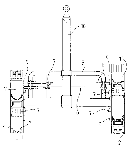
fig. 2 is a plan view of the brake apparaLus shown in
fig. 1,
fig. 3 shows the components of another brake mechanism
of the invention mounted on a disc wheel.
Referring to fig. 1, the forest cultivator includes two
disc wheels 1 and 1', with cultivating tools 2 extend-
ing radially from the outer periphery thereof. In this
exemplary case, there are three tools side by side.
The number of tools may just as well be one or more
than three side by side. The disc wheels 1 and 1' are
journalled to a forest cultivator body 3. A tractor
is used to drag the forest cultivator by means of a
boom 10 and, upon cultivating or spotting, said disc
wheels 1 and 1' are alternately braked by means of a
locking rod 8 and a locking shoulder 9, said cultivating
tools 2 working a spot by using alternately the right-
hand side and the left-hand side disc wheel 1 and 1',
respectively.
As shown in fi~. 2, the disc wheel 1' is clamped by
means of a locking rod 8. The locking rod 8 and a
control rod 6 are fastened to body 3 and adapted to
shift transversely back and forth relative thereto.
The locking shoulders 9 extending from the side of
disc wheel 1' facing said body 3, i.e. from internal
side, are located in alignment with locking rod 8. As

4 2~ 9,~;~8
disc wheel 1' is rotating, said locking shoulder 9 is
carried along with the disc wheel and comes to contact
with locking rod 8. This prevents the rotation of disc
wheel 1' and a braking cycle commences. At the same
time, said cultivating tools 2 lie against the ground
and produce a cultivating spot. The braking cycle
comes to an end as a contact element 7 included in ro-
tating disc wheel 1 on the opposite side urges said
control rod 6 serving as a release element over to the
side of clamped disc wheel 1'. ThuS, a transmission
lever 5 shifts said locking rod 8 over to the side of
opposite disc wheel 1 so as to release the clamped disc
wheel 1' to allow its rotation. The contact elements
7 and locking shoulders 9 included in disc wheel 1, 1'
are located so as to commence and conclude at a proper
moment.
Thus, according to figs. 1 and 2, the brake mechanism
includes at least one contact element 7, which is fast-
ened to each disc wheel 1 and 1' and typically com-
prises a bevel~faced member attached to the internal
side of disc wheel 1 and 1' and located in alignment
with control rod 6. As disc wheel 1, 1' is rotating,
said contact element 7 controls a release element,
which is included in the brake apparatus and comprises
a control rod 6 common to both wheels, pushing the con-
trol rod over to the side of clamped disc wheel 1'.
The movement of control rod 6 is adapted to be trans-
mitted to a clamping element, the latter comprising a
locking rod 8 common to both disc wheels 1 and 1'.
Said movement is transmitted through the action of a
transmission lever 5 pivotably journalled to forest
cultivator body 3. The transmission lever 5 can be
Eor example a rod, which is centrally pivoted to the
body and whose ends are fastened on the one hand to

2~
control rod 6 and on the other hand to a link mounted
on locking rod 8 or between two pins, as shown in fig.
2. Thus, the transmission lever 5 carries said locking
rod 8 over to the side of opposite, rotating disc wheel
1 so as to release said disc wheel 1', which has just
been in a clamped position.
The disc wheel 1 and 1' is fitted with extending lock-
ing shoulders 9, adapted to come in contact with lock-
ing rod 8 for locking or clamping said disc wheel 1.
When the next locking shoulder 9 of rotating disc wheel
1 comes in alignment with locking rod 8, those two are
forced in contact and said rotating disc wheel 1 is
clamped. The locking of disc wheel 1 having a culti-
vating shift occurs simultaneously as the cultivating
tool 2 is in a lower position and pressed against the
ground. This produces cultivating spots in turn on
alternating sides. In fig. 2, the brake apparatus is
depicted at a moment when the disc wheel 1 will be
clamped in just a while and disc wheel 1' is about to
be released.
Fig. 3 illustrates another design of a disc wheel 1.
This disc wheel 1 is only provided with two cultivating
tools 2 on the opposite sides of disc wheel 1. Another
difference between this disc wheel and those of figs.
1 and 2 is that a locking shoulder 9 is located closer
to the centre of disc wheel 1 than a contact element 7.
Thus, the locking rod and the control rod are also
located in reverse order as compared to figs. 1 and 2.
The end of cultivating tool 2 is on the same level as
the periphery of disc wheel 1. This offers the ad-
vantage that the cultivating device is not laterally
tiltable as it is not necessary to lift the disc wheel
1 on top of the cultivating tools 2 prior to a braking

2~7~ 8
cycle. This design is accomplished by removing from
disc wheel 1 a segmental section and by fitting in the
middle thereof said tools 2 extending up to the peri-
phery.
In the disc wheel of fig. 3, said locking shoulder 9
is provided with a rubber pad for a smooth locking or
clamping. In addition, said locking shoulder 9 is
extended as a back-up bracket 9', which is preferably
of equal height and width and arch-shaped. This arch-
shaped back-up bracket 9' makes sure that said locking
rod 8 is retained in a clamped position in front of the
locking shoulder of the other disc wheel. Once the locking
rod 8 moves out of a clamping position, i.e. the end
of locking rod 8 rises above the locking shoulder 9,
said back-up bracket 9' prevents the random backward
slipping of locking rod 8. Otherwise this would result
in a premature release of the opposite, clamped disc
wheel.
The disc wheel 1 can also be provided with a chain 4,
as shown for example in figs. 1 and 2, said chain 4
raking soil during a braking cycle for covering the
seeds and, for example, fertilizers.
The invention is not limited to the above embodiment
but it can be modified within the scope of the annexed
claims. Thus, for example a transmission lever 5 can
be replaced with a body-mounted gear having its top
and bottom in contact on the one hand with locking rod
8 and on the other hand with control rod 6.

2~39.'~3
The disc wheels 1 and 1' contain usual seed
compartments which comprise sowing openings after the
tools for sowing the seeds into the ground to the
spotS worked by the tools. These means are well-
known to a man skilled in the art and they are
therefore not described in more detail.

Dessin représentatif
Une figure unique qui représente un dessin illustrant l'invention.
États administratifs

2024-08-01 : Dans le cadre de la transition vers les Brevets de nouvelle génération (BNG), la base de données sur les brevets canadiens (BDBC) contient désormais un Historique d'événement plus détaillé, qui reproduit le Journal des événements de notre nouvelle solution interne.

Veuillez noter que les événements débutant par « Inactive : » se réfèrent à des événements qui ne sont plus utilisés dans notre nouvelle solution interne.

Pour une meilleure compréhension de l'état de la demande ou brevet qui figure sur cette page, la rubrique Mise en garde , et les descriptions de Brevet , Historique d'événement , Taxes périodiques et Historique des paiements devraient être consultées.

Historique d'événement

Description Date
Inactive : CIB de MCD 2006-03-11
Réputée abandonnée - omission de répondre à un avis sur les taxes pour le maintien en état 2000-06-12
Inactive : Morte - RE jamais faite 2000-06-12
Demande non rétablie avant l'échéance 2000-06-12
Inactive : Abandon.-RE+surtaxe impayées-Corr envoyée 1999-06-10
Demande publiée (accessible au public) 1993-12-11

Historique d'abandonnement

Date d'abandonnement Raison Date de rétablissement
2000-06-12

Taxes périodiques

Le dernier paiement a été reçu le 1999-05-10

Avis : Si le paiement en totalité n'a pas été reçu au plus tard à la date indiquée, une taxe supplémentaire peut être imposée, soit une des taxes suivantes :

  • taxe de rétablissement ;
  • taxe pour paiement en souffrance ; ou
  • taxe additionnelle pour le renversement d'une péremption réputée.

Les taxes sur les brevets sont ajustées au 1er janvier de chaque année. Les montants ci-dessus sont les montants actuels s'ils sont reçus au plus tard le 31 décembre de l'année en cours.
Veuillez vous référer à la page web des taxes sur les brevets de l'OPIC pour voir tous les montants actuels des taxes.

Historique des taxes

Type de taxes Anniversaire Échéance Date payée
TM (demande, 5e anniv.) - petite 05 1997-06-10 1997-05-26
TM (demande, 6e anniv.) - petite 06 1998-06-10 1998-05-20
TM (demande, 7e anniv.) - petite 07 1999-06-10 1999-05-10
Titulaires au dossier

Les titulaires actuels et antérieures au dossier sont affichés en ordre alphabétique.

Titulaires actuels au dossier
TOIMI JALMARI HOLCK
Titulaires antérieures au dossier
S.O.
Les propriétaires antérieurs qui ne figurent pas dans la liste des « Propriétaires au dossier » apparaîtront dans d'autres documents au dossier.
Documents

Pour visionner les fichiers sélectionnés, entrer le code reCAPTCHA :


Pour visualiser une image, cliquer sur un lien dans la colonne description du document. Pour télécharger l'image (les images), cliquer l'une ou plusieurs cases à cocher dans la première colonne et ensuite cliquer sur le bouton "Télécharger sélection en format PDF (archive Zip)" ou le bouton "Télécharger sélection (en un fichier PDF fusionné)".

Liste des documents de brevet publiés et non publiés sur la BDBC .

Si vous avez des difficultés à accéder au contenu, veuillez communiquer avec le Centre de services à la clientèle au 1-866-997-1936, ou envoyer un courriel au Centre de service à la clientèle de l'OPIC.


Description du
Document 
Date
(aaaa-mm-jj) 
Nombre de pages   Taille de l'image (Ko) 
Dessins 1993-12-10 3 53
Revendications 1993-12-10 2 47
Abrégé 1993-12-10 1 23
Description 1993-12-10 7 214
Dessin représentatif 1998-10-01 1 13
Rappel - requête d'examen 1999-02-10 1 116
Courtoisie - Lettre d'abandon (requête d'examen) 1999-07-21 1 172
Courtoisie - Lettre d'abandon (taxe de maintien en état) 2000-07-09 1 184
Taxes 1996-05-30 1 47
Taxes 1994-04-26 1 71
Taxes 1995-05-15 1 77