Sélection de la langue

Search

Sommaire du brevet 2072290 

Énoncé de désistement de responsabilité concernant l'information provenant de tiers

Une partie des informations de ce site Web a été fournie par des sources externes. Le gouvernement du Canada n'assume aucune responsabilité concernant la précision, l'actualité ou la fiabilité des informations fournies par les sources externes. Les utilisateurs qui désirent employer cette information devraient consulter directement la source des informations. Le contenu fourni par les sources externes n'est pas assujetti aux exigences sur les langues officielles, la protection des renseignements personnels et l'accessibilité.

Disponibilité de l'Abrégé et des Revendications

L'apparition de différences dans le texte et l'image des Revendications et de l'Abrégé dépend du moment auquel le document est publié. Les textes des Revendications et de l'Abrégé sont affichés :

  • lorsque la demande peut être examinée par le public;
  • lorsque le brevet est émis (délivrance).
(12) Demande de brevet: (11) CA 2072290
(54) Titre français: OUTIL DE NIVELAGE POUR PANNEAUX DE CONSTRUCTION
(54) Titre anglais: FORMING LEVELING TOOL
Statut: Réputée abandonnée et au-delà du délai pour le rétablissement - en attente de la réponse à l’avis de communication rejetée
Données bibliographiques
(51) Classification internationale des brevets (CIB):
  • G01C 09/28 (2006.01)
  • G02F 01/35 (2006.01)
  • H01S 03/23 (2006.01)
  • H01S 03/30 (2006.01)
(72) Inventeurs :
  • JULIA, JUAN L. (Etats-Unis d'Amérique)
  • JULIA, JUAN L. (Etats-Unis d'Amérique)
(73) Titulaires :
  • JUAN L. JULIA
(71) Demandeurs :
  • JUAN L. JULIA (Etats-Unis d'Amérique)
(74) Agent: KIRBY EADES GALE BAKER
(74) Co-agent:
(45) Délivré:
(22) Date de dépôt: 1992-06-25
(41) Mise à la disponibilité du public: 1993-02-28
Requête d'examen: 1992-10-16
Licence disponible: S.O.
Cédé au domaine public: S.O.
(25) Langue des documents déposés: Anglais

Traité de coopération en matière de brevets (PCT): Non

(30) Données de priorité de la demande:
Numéro de la demande Pays / territoire Date
750,665 (Etats-Unis d'Amérique) 1991-08-27

Abrégés

Abrégé anglais


ABSTRACT OF THE DISCLOSURE
A tool for mounting and leveling forming boards to a vertical wall
that has three legs parallel to each other. Two of these legs are separated
sufficiently to permit a forming board only between them while the third
leg is separated a larger distance and typically the distance between two
spaced apart forming boards. A puncturing mechanism is mounted to the
outer leg of the pair that accepts the forming board so that it can be
releasably held. A leveling device is mounted on a transverse member that
connects all three legs.
Page 9 of 9

Revendications

Note : Les revendications sont présentées dans la langue officielle dans laquelle elles ont été soumises.


Claims:
1. A tool for mounting and leveling forming boards to a
vertical wall, comprising:
A. first and second leg members having each two ends wherein
said first leg member is longer than said second leg
member;
B. a transverse member rigidly and perpendicularly mounted
to one of the ends of each of said leg members;
C. a puncturing assembly mounted to said first leg member
and further including a puncturing element that is
selectively forced inwardly to puncture one of said
boards holding same securely in place;
D. a third leg member rigidly and perpendicularly mounted to
said transverse member and said third leg member being
mounted at a parallel and spaced apart relationship with
respect to said first member so that separation of said
third and first leg members is sufficient to permit said
one of said forming boards through and wherein said third
leg member is shorter than said first and second leg
members;
E. handle means mounted to said transverse member; and
F. level means longitudinally mounted along said transverse
member.
Page 7

Description

Note : Les descriptions sont présentées dans la langue officielle dans laquelle elles ont été soumises.

2~7229~
I. TITLE: FORMING LEVELING TOOL
II. BACKGROUND OF THE INVENTION
1~ Field of the Invention.
The present invention relates to tools utilized to rnount Iqat and
substantially elongated boards to a vertical wall and more particularly to
such tools that permit the user to hold and level said boards.
In the building construction industry carpenters typically form the
cavities where the concrete is going to be pouring with two sheets of
plywood that are kept at a spaced apart relationship to each other and in
most instances the sheets need to be leveled. This task becomes
particularly difficult when a carpenter needs to mount one of such boards,
typically plywood, to an outer surface of a wall. If scaffolds are not used, a
helper is required to hold the board to be mounted in place while ~he
carpenter drives the first nail through. The difficulty increases with the
height of the wall and the size of the board is to be mounted. Even if
scaffolds are used, a helper is typically required.
III. SUMMARY OF THE INVENTION
It is one of the xnain purposes of the present invention to provide a
tool that can be readily mounted to an elongated I1at board or sheet of
plywood to be used as a forming element in order to keep it in place until a
user permanently affixes it to the surface of a wall.
"
.
-
'
'
' ', , ~ "' '' '`~.,' ', ',
;,.

~22~
-
It is another purpose of the present invention to provide such a tool
that can permit the vertical adjustment of its position with respect to end
of the wall where the forming is taking place in order to take into account
all the subsequent activities such as the pouring of a slab of concrete.
It is yet another object of this invention to provide such a device that
is inexpensive to manufacture and maintain while retaining its
effectiveness.
Further objects of the invention will be brought out in the following
part of the specification, wherein detailed description is for the purpose of
fully disclosing the invention without placing limitations thereon.
IV. BRIEF DESCRIPTION OF THE DRAWINGS
With the above and other related objects in view, the invention
consists in the details of construction and combination of parts as will be
more fully understood from -the following description, when read in
conjunction with the accompanying drawings in which:
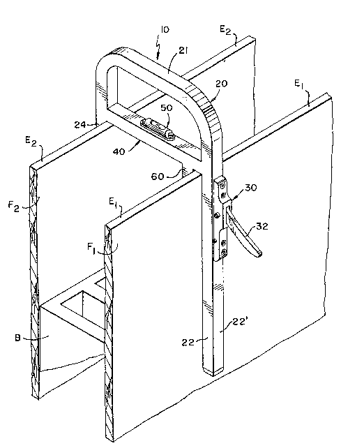
Figure 1 represents an isometric view of one of the embodiments of
the present invention mounted to an elongated flat board to be used as a
forming element in construction.
Figure 2 is an elevational front view of the present invention being
adjusted for the pouring of a slab.
Page ~ of 9
'~

2~7229~
Figure 3 shows an elevational fro:nt view of the present invention
being used -to pour a tie-beam.
Figure 4 is a detail side view of the puncturing assembly.
Figure 5 illustrates how a user mounted a formirlg board on the
exterior surface of a wall.
Figure 6 shows how a user finalizes the mounting of the board.
. DETAILED DESCRIPTION C)F THE PREFERRED EMBODIMENT
Referring now to the drawings, where the present invention is
generally referred to with numeral lû.
The present invention is preferably made out of rigid material, such
as steel, and it includes a U-shaped assembly 20 that has long leg 22 and
short leg 24 that are of sufficient length to securely ride on top of forming
boards Fl and F2.
Long leg 22 includes puncturing assembly 30 mounted on the outer
surface 22' of leg 22. Assembly 30 includes actuating lever 32 so designed
and constructed to camrningly push in pointed member 34 inwardly to
effectively engage forming board Fl, as best seen in figures 2 and 3.
Transversal member 40 is rigidly and perpendicularly mounted to legs 22
Page 3 of 9
;

~722~
and 24. Shorter leg 24 can be made of the same si~e as leg 22, however, it
has been found that it is easier to handle tool 10 for reading :rnounting it
and demounting it. The separation of legs 22 and 24 is suffic;ent to perrx~it
the mounting of device 10 on forming boards Fl and F2 according to the
width of the wall which will be determined by the width of the block.
Transversal member 40 includes level assembly 50 that permits a user
to determine whether the upper edge El board Fl being installed is at a
leveled position with respect to already installed and leveled board F2 and
prior to driving in the first few nails to permanently secure forming boards
Fl to concrete blocks B.
It is to be understood that U-shaped assembly 20 can also have a
slight different shapes without departing from the spirit of the invention if
basically two legs 22 and 24 and inner leg 60 relatively closer to leg 22
are mounted to a spacer or transversal member 40 so that it can ride on
forrming boards Fl and F2 The upper end 21 of assembly 20 functions as a
handle. The same is true as to the cross-section of assembly ~0 or the
material it is made out of can also be substituted with any other rigid
material. In the preferred embodiment the cross sectional shape of
assembly 20 is square or rectangular so that the surfaces adjacent to
boards Fl and F2 are positioned flat against the latter.
Page 4 of 9
.` , , ,1 ` ', .,., :

-` 2~7~29~
Sometimes the pouring of a slab requires that the position of device
10 be offset in the vertical direction to allow for such operation as shown in
figure 2. L-shaped screw member 70 can be utilized to provide supporting
engagement that will permit transversal member 40 to align its lower
surface with the upper surface of the concrete slab C to be poured.
In figure 3, con~entional forming boards Fl and '.~2 are being used to
pour a tie beam. In operation, tool 10 is secured to forming board Fl (Fl is
on the outside) through the engagement of pointed member 34 into board
Fl.
Puncturing assembly 30 is preferably implemented as shown in figure
4. Lever 32 cammingly causes the inward motion of pointed member 34 to
securely hold board Fl Lever 32 is designed to be pivotally mounted to
pin 31 inside housing 33.
As It can be seen from figures 5 and 6, a user can use the present
invention to single handedly install forming board Fl to an exterior wall
surface. This becomes increasingly useful when the surface is at high
floors and there are no scaffold. A user basically mounts tool 10 to board
~1 on the floor and swings over (already attached~ wall W, as shown in
figure 5. The internal forming board F2 is already installed. The user then
causes leg 24 to abuttingly mount adjacent to the inner (inside the building)
Page 5 of 9

2~72~9~
surface of board F2. Transverse member 40 rests on edge E2. A user can
check leveling assembly 50 to make sure that edges El and E2 are leveled,
then he or she proceeds to drive the nails (or any other fastening device)
through board Fl and into wall W.
It is believed the foregoing description conveys the best
understanding of the objects and advantages of the present invention.
Different embodiments may be made of the inventive concept of this
invention. It is to be understood that all matter disclosed herein is to be
interpreted merely as illustrative, and not in a limiting sense.
Page 6 of 9
i "; " , ~ "
".,
.. . ...
; . ~ . , -

Dessin représentatif
Une figure unique qui représente un dessin illustrant l'invention.
États administratifs

2024-08-01 : Dans le cadre de la transition vers les Brevets de nouvelle génération (BNG), la base de données sur les brevets canadiens (BDBC) contient désormais un Historique d'événement plus détaillé, qui reproduit le Journal des événements de notre nouvelle solution interne.

Veuillez noter que les événements débutant par « Inactive : » se réfèrent à des événements qui ne sont plus utilisés dans notre nouvelle solution interne.

Pour une meilleure compréhension de l'état de la demande ou brevet qui figure sur cette page, la rubrique Mise en garde , et les descriptions de Brevet , Historique d'événement , Taxes périodiques et Historique des paiements devraient être consultées.

Historique d'événement

Description Date
Inactive : CIB de MCD 2006-03-11
Le délai pour l'annulation est expiré 1995-12-25
Demande non rétablie avant l'échéance 1995-12-25
Réputée abandonnée - omission de répondre à un avis sur les taxes pour le maintien en état 1995-06-26
Inactive : Demande ad hoc documentée 1995-06-26
Demande publiée (accessible au public) 1993-02-28
Toutes les exigences pour l'examen - jugée conforme 1992-10-16
Exigences pour une requête d'examen - jugée conforme 1992-10-16

Historique d'abandonnement

Date d'abandonnement Raison Date de rétablissement
1995-06-26
Titulaires au dossier

Les titulaires actuels et antérieures au dossier sont affichés en ordre alphabétique.

Titulaires actuels au dossier
JUAN L. JULIA
Titulaires antérieures au dossier
S.O.
Les propriétaires antérieurs qui ne figurent pas dans la liste des « Propriétaires au dossier » apparaîtront dans d'autres documents au dossier.
Documents

Pour visionner les fichiers sélectionnés, entrer le code reCAPTCHA :


Pour visualiser une image, cliquer sur un lien dans la colonne description du document. Pour télécharger l'image (les images), cliquer l'une ou plusieurs cases à cocher dans la première colonne et ensuite cliquer sur le bouton "Télécharger sélection en format PDF (archive Zip)" ou le bouton "Télécharger sélection (en un fichier PDF fusionné)".

Liste des documents de brevet publiés et non publiés sur la BDBC .

Si vous avez des difficultés à accéder au contenu, veuillez communiquer avec le Centre de services à la clientèle au 1-866-997-1936, ou envoyer un courriel au Centre de service à la clientèle de l'OPIC.


Description du
Document 
Date
(aaaa-mm-jj) 
Nombre de pages   Taille de l'image (Ko) 
Revendications 1993-02-27 1 32
Dessins 1993-02-27 3 88
Abrégé 1993-02-27 1 22
Description 1993-02-27 6 217
Dessin représentatif 1999-06-07 1 24
Taxes 1994-06-22 1 76
Correspondance de la poursuite 1992-10-15 1 36
Correspondance de la poursuite 1993-07-01 1 35
Courtoisie - Lettre du bureau 1992-11-29 1 42