Note : Les descriptions sont présentées dans la langue officielle dans laquelle elles ont été soumises.
7~
The invention concerns a covering for building facades
etc., comprised of a preasssmbled support frame connected to
the building facade and essentially rectangular covering
panels connected in a detachable manner to the support frame,
whereby the support ~rame contains vertically extending
profiled rails for supporting and attaching thereto the edges
of the covering panels.
Facade coverings with covering panels made of mineral
materials such as, for example, marble are common in which
the covering panels in principle are connected to the
building facade in an invisible manner whereby bolts or
similar anchors are connected to recesses of the covering
- panel backside on the one hand and, on the other hand, to the
building facade, for example, by cementing. This is
especially disadvantageous because a later removal of the
covering panels is only possible by destroying the covering
panQls. With other commonly used facade coverings a later
releasable attachment of the covering panels to a
preassembled support frame, for example, made of profiled
rails of aluminum is employed; however, this known covering
construction has the disadvantage that elements of the
releasable panel attachment are visible at the front face o~
the covering panels or at least within the seams between the
covering panel edges so that the visual appearance of the
~acade covering is impaired.
The present invention provides a covering ~or building
Pacades or, for example, also for interior buildin~ walls in
which the covering panels are attached in an invisible as
well A8 releasable and removable manner to the building
~aaada~
. .
- 1 -
2~72~13
More particularly, the covering for building facades
according to the present invention is primarily characterized
by:
Essentially rectangular covering panels that are
vertically positioned, having a front face and a lower edge
surface which is reces~ed relative the front face and having
two lateral edges with at least one portion that has an edge
surface recessed relative to the front face, the edge surface
having a recessed receiving pocket;
A preassembled support frame connected to the building .
facade, with the covering panels connected to the support
frame, the support frame comprising vertically extending
profiled rails ~or supporting and fastening the covering
panel~, with two neighboring ones o~ the lateral edges of two
1~ ~d~acent ones o~ the covering panels fas-tened to a common one
o~ ~he profiled rails;
The support frame having a bracket for each aovering
panel for receiving the weight of covering panel being placed
with the lower edge surface onto the bracket:
~0 The profiled rails having two hollow boxes spaced from
one another and positioned behind the lateral edges of the
~d~cent panels, each hollow box having an opening at a face
that is Pacing the other hollow box;
~ ach hollow box comprising a holding element inserted
into the hollow box, the holding element having a hook-shaped
por~ion axtendinq past the opening, the holding element being
ho~l~ontally slidable parallel to the plane o~ the covering
p~nels, with the opening o~ the hollow box, at a location
2~72~3
above the receiving pocket, having a widened portion through
which the holding element is inserted into the hollow box and
lowered to the elevation of the receiving pocket, and with a
free end of the hook-shaped portion being inserted into the
receiving pocket by horizontally sliding the holding element
within the hollow box parallel to the plane of the covering
panels.
Preferably, the lower edge surface has a holding pocket
and the bracket has an upwardly bent lower end engaging the
holding pocket and holding the covering panel against the
support frame.
In an advantageous embodiment, the width of the upwardly
bent lower end corresponds essentially without play to the
width of the holding pocket, and the width of the free end of
the hook-shaped portion corresponds essentially without play
to the width of the receiving pocket.
In a further embodiment of the present invention, a
faQtening member is provided that is placed on the hook-
shaped portion of the holding element from the top, the
fastening member securing itsel~ against horizontal
displacement at the profiled rail and blocking the holding
element against horizontal displacement within the hollow box
~n the position in which the free end o~ the hook-shaped
portion is inserted into the receiving pocket. The ~astening
~5 member may secure itself directly or indirectly.
~ he covering ~or building facades preferably ~urther
comprises a U-shaped holding bracket for attaching the
covaring panels to a corner where a ~irst and a second
building facad~ meet. In this embodiment, the pro~iled rail
3~ - 3 -
, ., . ~ ..... ~ . ,~: .. ,.. , , ....... . :;
.. . .., . .: ., ,.: :,.,. : . , .
: . : , . . ,,,, . . ., -. .:
2~72~13
on the first building facade has a receiving groove that
opens in a direction toward the covering panels, the U-shaped
holding bracket having a first leg that is inserted into the
receivinq groove and a second leg that is inserted into the
receiving pocket of one of the covering panels arranged on
the second building facade along a longitudinal side of the
profiled rail. Preferably, the profiled rail has a receiving
groove on either longitudinal side.
-
An embodiment and the function of the inventive covering
will be described in the following with the aid of thedrawing representing an exemplary embodiment, wherein:
Fig. 1 a vertical cross-section of a
portion of a covering panel
and the support frame; ;`
1~ Fig. 2 a horizontal cross-section of
the support frame and of two
neighboring covering panels
arranged in the same covering plane:
Fig. 3 a horizontal cross-section of the
support frame and two covering
panels which are positioned at a
building corner between two aoverin~
planes arranged at a right angle relative
to one another.
as The covering is comprised of the support frame indiaated
~enerall~ with reference numeral 1 in Fig. 1 and comprising
~k least vertiaally extending profiled rails 7, for example,
. ~
_ 4 _
:. ~ .,: . , .
2072al3
made of aluminum, and covering panels 2 which are essentially
rectangular and may be comprised of, for example,
synthetically manufactured marble. The covering panels 2
have a thickness which, on the one hand, is sufficient to
provide the required stiffness to the covering panels with
respect to, for example, wind pressure and wind suction and,
on the other hand, is required for embodying the covering
panels according to inventive measures.
.
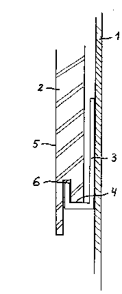
The support frame 1 has at least one bracket 3, for
receiving the weight of eac~ covering panel 2. The covering
panel 2 is placed on the bracket 3 with its lower edge
surface 4. of course, the bracket 3 may be positioned at the
correct location of the support frame relative to the shape
and the height o~ the covering panel with respective
~mbodiments and measures that are not detailed further. The
b~acket 3 may be a simple support on which the covering panel
ra~t5 ~or its weight distribution. The edge surface ~ is
recessed, for example, by cutting the panel edge within the
q~ea o~ the bracket 3 behind the front face 5 of the covering
panel 2 so that the bracket 3 is invisible at the front face
S o~ the facade covering.
Advantageously, the covering panel 2 is furthermore
provided with a slot-like cut-out holding pocket 6 at the
~wardly rece~sed lower edge surface 4 which is engaged
fro~ the bottom by the hook-shaped bracket 3 rapresented in
Fi~ure 1. The bracket 3 not only bears the weight of the
covering panel 2, but also holds the covering panel 2 with
it~ lower end clo5e to the support frame 1 so that, dependiny
on ~he hei~ht o~ the covering panels 2r it may be sufficient
- 5 -
2072~13
to provide a further, invisible as well as detachable
attachment only at the upper end of the covering panel, (see
Figure 2).
In order to invisibly and detachably attach the
neighboring lateral edges of two covering panels 2, which are
arranged in the same covering plane, at least one location of
their lateral edges to a common vertically extending profiled
rail 7 of the support frame 1, the profiled rail 7 has two
vertical hollow boxes 8. The hollow boxes 8, in cross-
section, are preferably rectangular and arranged at ahorizontal distance relative to one another behind the two
neighboring lateral panel edges. The hollow boxes 8 are
embodied with openings 10 at their sides 9 facing one
another. A holding element 11 inserted into the hollow box 8
protrudes through this opening 10. The section of the
holding element 11 which is positioned inside the hollow box
8 is formed such that the holding element 11 is restrained by
the hollow box 8 against movement in a direction vertical to
the covsring plane (from the top to the bottom in Fig. 2).
However, the holding element 11 may be moved to a limited
extent in a horizontal direction parallel to the covering
plane (from the left to the right in Fig. 2). The portion of
the holding element 11 which extends fxom the hollow box ~ is
provided with a hook-shaped portion 12. The covering panel
~5 2, at the location of its lateral edge at which the
connection via the holding element 11 shall be achieved, is
provided with an edge surface 13, similar to the edge surface
embodiment shown in Fig. 1, that is recessed relative to the
~ront face 5 o~ the covering panel 2 and from which extends a
~0 cut-out receiving pocket 14. Into this receiving poaket 14
the hook-shaped portion 12 of the holding element is inserted
- 6 -
2~2~13
by horizontally sliding the holding element 11 within the
hollow box 8. In this position the holding element 11 is
invisibly covered by the covering panel 2.
The width of the hook-shaped holding element portion 12
5 corresponds essentially to the width of the receiving pocket
14 so that the hook-shaped portion 12, in a direction
vertical to the covering panel plane, engages essentially
without play the receiving pocket 14. The same holds true
~or the bracket 3 represented in Figure 1 when the bracket is
lo not only designed to hold the weight of the panel, but also
to fix the lower end of the covering panel 2 at a certain
distance from the building facade.
In order to release one of the two panel attachments
represented in Fig. 2, it is only necessary to introduce a
1~ hook-shaped tool through the commonly present slot between
~ha two adjacent lateral panel edges and to move the holding
element 11 within the hollow box 8 or to pull it outwardly
un~il the hook-shaped portion 12 is released from the
receiving pocket 14.
O Above the receiving pocket 14 of the covering panel 2
the opening 10 of tha hollow box 8 is widened to such an
axtent that the holding element 11 at this location o~ the
hollow box, respectively, o~ the pro~iled rail 7, may be
po~itioned between the two hollow boxes 8 and then inserted
into the hollow box 8 via the widened portion: From this
po3ition the holding element 11 is then vertically lowered to
tha haight oP the receiving pocket 1~ oP the covering panel
~, whareby diPPerent suitable abutments at the
-- 7 --
.; .
~72~13
profiled rail 7 or within the hollow box 8 may be provided
which prevent a downward fall of the holding element 11 below
the receiving pocket 14.
During the mounting of the facade covering, which takes
places from the bottom to the top, a fastening member in the
form of an arresting plate 15 provided with two slots
extending from the lower edge may be placed onto the two
holding elements 11 engaging the covering panels 2. The
arresting plate 15 prevents an accidental displacement of
lo both holding elements 11 from their engaging position with
the covering panels 2. For a desired release of the covering
panel attachment, the arresting plate 15 may be lifted off
the two holding elements 11 by inserting a suitable tool into
the slot between the two covering panel edges. Subsequently,
1~ thQ plate 15 may be returned to its position on the two
holding elements.
Represenked in Fig. 3 is a releasable and invisible
connection for two covering panels 2 and 21 which abut at the
corner of a building. The profiled rail 7, which is
connected to one of the building facades forming the building
corner, is provided with a forwardly open receiving groove 22
at least at its longitudinal side facing the building corner,
pre~erably at both longitudinal sides. A leg 23 of a U-
~h~ped bracket 24 is inserted into this receiving groove 22.
~$ T~e other leg 23a o~ this bracket 24 engages the lateral
reaeiving pocket 14 o~ the covering panel 21. The covering
panel 2 which is arranged on the building ~acade holding thQ
pro~ilad rail 7 is arrested by the holding element 27 which
i~ inser~ed into the hollow box 8 o~ the profiled rail 7
lng the building corner. For this purpose, the portion o~
holding element 27 extending from the hollow box 8, in
- 8 -
2~2~3
contrast t~ the holding element 11 in the right half of the
Figure 2, is not provided with a hook-shaped end but with a
U-shaped end 25 in order to be able to engage the lateral
receiving pocket 14 of the covering panel 2 in analogy to the
embodiment shown in the left half of ~igure 2. For securing
this holding element 27 and, simultaneously, the bracket 24
in the position holding the covering panels 2 and 21~ a
~astening member or arresting plate 26 may be employed having
slots at its ends and being insertable onto the holding
element 27 and the bracket 24. For its arresting, the
bracket 24, may also be embodied such that only when the
covering panel 2 is removed or laterally displaced it may be
completely removed from the receiving pocket 14 of the
covering panel 21.
2a
; , ~ , , "
. . , ... , ;~ ~ ~ , .... .
`' ` ` '