Note : Les descriptions sont présentées dans la langue officielle dans laquelle elles ont été soumises.
;~:Q7~
DESCRIPTION
S~I~LL,-SIZED DC ~IOTOR
TECHNICAL _IE~D
The present invention relates to a smal.L-si~ed DC mo-tor
characterized in -that a PTC (posi-tive temperature coetEicien-t~
thermistor which is applied to a fixed-temperature heating resis-
tor, a -temperature sensor! a curren-t limitin~ element, and so on,
is incorporatecl into or circumscribed on the motor as the over-
load protection element for the motor.
BACKGROUND OF THE INVENTION
Mainly a bimetal, a PTC thermistor, etc. are known as over-
current protection elements to be used as a measure counter an
overload of a small-sized DC motor, and there is a tendency that
the amount of use of those elements increases particularly
centering the Eield of car industries.
Of those elements, a bimetal is connected in series mainlY
to a motor having a diameter of 40 mm~ or more, that is, having
~an overload current of about 5A or more, and usually used as the
~;~ motor bu1lt-in -type.
Generally, when an overload current is not larger than 5A,
the accuracy of switching operation of a bimetal is low so that
~the bimetal fails to perform stable operation. Accordingly, a
:~ :
~ PTC thermistor having a cost lower than that of the bimetal is
:
broadly used.
`~ As is known, a PTC thermistor is a resistor element having a
positlve temperature coeff~icient, and al-though the resistance
value thereof is low at an ordinary temperature, the value sud-
denL~ increases to be 104 - 107 times as large as the value at an
ordlnary~ temperature if the e`lement reaches or exceeds a pre-
:
~:
- ~
, - :
-
~73~5
determined swi-tching temperature beca~lse of self heating or heat
-trans~er from a cer-tain heat source.
A PTC thermistor made of BaTiO3 ceramics is most generall~
known, and a PTC thermistor of ~23 ceramic ? a resin PTC -ther-
mistor in which conductive par-ticles such as carbon black or -the
like are contained in polyolefin resin, and the liket are known
in addition to -the BaTiO3 PTC -thermis-tor.
Conventionally, a PTC thermistor to be used in a small-sized
DC motor is made of semiconductor ceramics containing BaTiO3 as
the principal component. Because of limita-tion in the material
characteristic that the resistivity of the material must be not
lower than 8 Q cm and the dielectric strength bust be in a range
of 30 50 V/mm, in use, a PTC thermistor is usually connected in
series to a motor as a disk-like part provided wi-th a lead wire
havin~ a diameter not thinner than 10 - 12 mm ~ . Since a PTC
thermistor cannot be incorporated into a motor because of its
shape and its size, however, ~t is general that a separate PTC
thermistor is mounted on the outside a motor through a printed
substrate or the like.
Consequently, there has been a problem that it takes a lon~
time to mount a PTC thermistor, and development of a small-sized
motor, even a small-sized motor havin~ a diameter smaller than ~0
mm ~ , provided with an overload protection element is desired by
a car industrial field, etc., who seek reduction in size and in
weight.
In such a background~ the inventors of this appLication
previously proposed "A small-sized DC motor" (Japanese Patent
~: :
Appl~cation No. Nei-1^292397) and "A small-sized DC motor
(Japanese Patent Application No. Hei-1-292398~. They are those
:~ : :
. ~
:. '
.: .
. ~ ~
~?7;~ s
structured fundamentally with ma-terials havin~ charac-teris-tics
considerably improved than -those of the conventional ~na-terials.
Next, those motors will be described.
The t`irs-t small-sized DC motor disclosed in Japanese Pa-tent
Application No. Hei-1-292397 is characteri~ed in that a BaTiO3
ceramic in which the ratio ~VD/ P 25) ~ the dielec-tric s-treng-th
VB (V~mm) to an ordinary-temperature resistivity P 25 ( Q cml is
not smaller than ~ and not larger than 20 is connected in series
to an armature winding and the PTC thermistor is incorpora-ted in
a motor casing. The BaTiO3 ceramic is formed oE, as starting raw
materials, a mi~ed crystal or a solid solution of BaTiO3, SrTiO3,
PbTiO3, and CaTiO3 synthesized through a liquid-phase solution
reaction method, and a valency control agent and Mn and Si which
are added to the above principal components by predetermined
amounts. Further, as the arrangement position of the PTC ther-
mistor made of the foregoing materials, places such as a position
between a phosphor-bronze plate connected to a brush of the
small-sized DC motor and input terminals, a position between -the
brush and the phosphor-bronze plate connected to the input termi-
nals, etc. have been proposed.
The small-sized DC mo-tor disclosed in Japanese Patent
Application No. Hei-1-292398, on the other hand, is characterized
in that a resin PTC thermistor is connected in series to an arma-
:~ ture winding and incorporated in a casing of the motor. The
material of the PTC thermistor a mixture oE polyolefin or
halogen-insulating resin and a high conductive material of a
carbon~group, the mixture generally having ordinary-tempera-ture
resistivity oE l - 2 Q cm and dielectric strength not lower than
l00 V/mm.~Further, as the posltion where the PTC thermistor made
:::
~ 3
'
,
. :
:
2~?7~ '3~i
of the foregoing material is -to be provided, a position between a
phosphor-bronze plate connec-ted to an input termi.nal and a brush
of the small-sized Dc mo-tor, a position between -the brush and the
phosphor-bronze plate connected to the input terminal, etc., have
been proposed.
Both -the above small-sized DC motors are characterized in ..
that the PTC thermis-tor is formed in-to a small-sized or thin
plate-like chip or into a cyLindrical shape or a shape accordin~
the foregoing shape and disposed in the inside of the motor, on
the basis of t,he fact that the material characteristic of the PTC
thermistor, particularly, the dielectric strength and the
ordinary-temperature resistivity have been considerably irnproved.
Each of the above proposed small-sized DC motors, however,
has the following problems, while the PTC khermistor superior in
material characteristic is formed like a chip and incorporated
into the motor so as to make the motor have an overload protect-
ing function itself and be reduced in size as well as in weight.
(1) With respect to the position where the PTC thermistor is
incorporated in the small-sized DC motor and -the shape of the PTC
thermis-tor, a plate-like PTC thermistor having electrodes at its
opposite surfaces and being arranged between the input terminal
and the pho.sphor-bronze plate connected to the brush, a PTC ther-
mistor having electrodes at its opposite surf'aces and being ar-
ran~ed between the input terminal and the phosphor-bron~e plate
connected to the brush, a cylindrical PTC thermistor having elec-
trodes at its opposite end surfaces and being arranged on a ter-
minal board, etc. have been proposed. In each o~'-the cases,
there is a possibility of occurrence of problems that the space
for position of arrangement is very small so that the size of the
. . - :
,
2~73~
chip-shaped PTC thermistor is limited because of the foregoing
limi-tation of -the space, -the moun-tirlg is not easy, the PTC ther-
mistor may be allowed -to come off or damaged by vibrations and/or
shocks.
(2) In a motor having internal resistance not lar~er than about
4 Q even if the motor has a diameter no-t larger than 40 mm~,
the PTC thermistor which matches with -the motor mus-t have a re-
sistance value not larger than 1 Q . Assuming that such a PTC
thermistor is formed by using the materials proposed in Japanese
Patent Application No. Hei-1-292397, then the size of the ther-
mistor is no-t smaller than about ~mm X ~mm in the case of the
square chip, and in order to mount the PTC thermistor in the
casing with no problem, a considerable device is required in view
of space and vibration-resistance.
(3) Although detailed description will be made later with re-
spective to the embodiment, a PTC thermistor is a heating resis-
tor, and the resistance value of the thermlstor under a predeter-
mined condltion i5 determined by a balanFe between the heat gen-
eration of the thermistor itself owing to Joule heat and the heat
:
radiation to the circumference. That is, the resistance value
relates to not only the shape of the thermistor and the circum-
ferential h.eat environment but the hea-t capacity of the ther-
mistor, that is, the size thereof. In other words, this fact
~m~ans that the smaller the si.ze of the thermistor becomes the
smaller:the heat capacity thereof becomes so that thermistor
: becomes~more :sensitive against a circumferential influence.
:
Consequently, in the case where a thermistor is merely de
creased:in size by using a material. having a large ratio of di-
electric strength to resistivity and is incorporated in a motor
.
:
.
,
., ~, . . . . . .
2~73~
as shown in the preceding proposal~ when an overloaded state
occurs in the motor~ h&at ~enera-tion of a motor coil is trans-fer
red -to the PTC thermistor through a phosphor-bronze plate or the
like by -the heat coupling effect so that the temperature of the
PTC thermistor i9 raised easil~. Accordingly, there is a defect
that the Joule heat of the PTC thermistor is transferred to the
motor -to thereby increase the limitation current value, while the
response of the switching operation of the PTC thermistor is made
high, and in the current limiting state, on the contrary, the
dielectric strength is made high because of such a function as if
a radiation plate, is provided. Consequentl~, if the the PTC
thermistor is merely reduced in size, a bad influence is rather
generated in view of heat capacity.
~4] The fundamental point of the foregoing proposals is in the
material in which the ratio of the d1electr1c strength to the
ordinary-temperature resistivity is remarkably improved in com-
parison with the conventional one. The material is a BaTiO3 PTC
ceram1c synthesized through the 11guld-phase solution reaction
method~, or PTC res1n. Those mater1als are hi~her in cost than
B~aT103~ ceramic prepared by the conventional solid phase method,
and~therefore such a~PTC thermistor~-that can be incorporated in a~
motor even~if lt 1S mads of ths convsnt1onal material has been
desired.
DISCLOSURE OF THE~INVENTION
An~obJsct~of the~present~1nvsnti~on is to prov1de a~small-
s1sed DC~motor in wh1oh a PTC thermistor wh1ch can be incorpo
rated 1n~thè motor e~en whsn ~1t~is formed of a~conventional mate-
ri~al,~which~can be easily mounted attached even if the motor has
;a d1ametsr not~larger~than 40 mm ~ and 1nternal rssistance not of
. ~ .
:~ : '
-: .
. .
~73~
larger than about ~ Q , which has no problem i.n space and in
vibration resistance, and which ls inexpensive.
Three important. factors in configuration of the present
invention are as follows.
A first one is a way how to increase -the dielec-tric stxength
with the conven-tional material. That is, this is because if the
dielectric strength can be increased, the thickness of -the ele-
ment can be reduced and the element is decreased in size to
-thereby make it possible to be incorpora-ted in or to be circum-
scribed on a mo-tor.
Next, the dielectric strength of a PTC ma-terial will be
described.
as shown in Fig. 4, The PTC material~ particularly the
BaTiO3 ceramic PTC material,~is a semiconductor generally having
of such a resistance/tempera-ture characteristic that the tempera-
ture gradient has a negative gentle gradient in the vicinit~ of
an ordinary temperature ~an NTC region), but the resistance value
suddenly increases with a width of change of about 104 107
tiJnes ta PTC region~ when the temperature exceeds a Gurie point A
as shown in Fig. 4. Then, a negative temperature gradient is
generated again (NTC region) when the temperature further in-
creases to.exceed a point B.
Fig. 5 shows the voltage/curren-t characteristic of the PTG
ceramic material having such .a resistance/temperature character-
istic. :In Fig. 5j the region from a point P to a point Q is a
fixed resistance region where a current increases in proportion
to voltage rising, and the temperature of the element is rai.sed
: ~ :
gradually by Joule heat, and the region corresponds to the fixed-
resistance region from the ordinary -temperature to the Curie
: : :
::
'
.
.
.
- : -
:~ .
2~7~?.~9S
point in Fig. ~. The region from the poin-t Q -to a poin-t R in
Fig. 5 is a fixed-power re~ion where the current clecreases in
inverse propor-tion to voltage rising ancl corresponds to the PTC
region from the poin-t A to the point B in Fi~. 4. In Fig. 5,
when the vol-tage i5 further increased~ the temperature o-E -the
element further rises to enter the NTC region not lower than the
poin-t B of Fig. ~, and -therefore the element is burnou-t broken by
the rockless run of -temperature rising. The voltage immedia-tely
before the burnout break is called dielectric strength VB of a
PTC material.
Thus, unlike a dielectric, the dielectric strength of the
PTC ceramic is defined to be a voltage which can endure burnout
break due to Joule heat. Unlike the BaTiO3 PTC material, a resin
PTC material has no NTC region not lower than the point B in Fig.
4, and it is therefore considered that the dielectric strength of
the resin PTC material rather corresponds to the dielectric
strength of the resin itself.
Since the dielectric s-trength of a generally widely used
P5aTiO3 PTC material is a voltage which can endure burnout break
due to Joule heat as described above, it lS said that the dielec-
trlc strength varies in accordance with the condition of radia-
tion of Joule heat from the element~ That is, the dielectric
strength oP the PTC material is not a physical constant but a
value synthetically determined in accordance with no-t only the
material characteristic of the element bu' the shape thereof, the
circumferential heat environment5 and the like. In the case of
~: :
evaluating the dielectric strength of the PTC material itself,
therefore, the inventors of this application use measurement
values obtained when an annulax disk having a diame-ter of 10 mm~
:: `
.
- ,
'
- . '
,
3~
and a thickness of 1 mm is set a-t a predetermined temperature and
in a atmosphere where no convec-tiorl e~ists. In view ot part
design, on tbe o-ther hand, in order to raise -the dielec-tric
streng-th, such a measure -that, for example, a heat radiation
pla-te is attached onto a PTC thermistor is widely carried out to
improve the heat radiation property.
From such a poin-t of view, the inventors of this application
have earnestly investigated -the shape oE a PTC -thermistor which
can be incorporated in a motor nnd which can improve the dielec-
~ric streng-th, and as a result, they have found that the above
condition can be satisfied by a so-called dou~hnut-shaped PTC
thermistor which is formed of an annular or square plate-like
body or a plate-like body similar to the former, an openin~ por-
tion being formed at the center of the plate-like body.
That is, the inventors have found that doughnut-shaped PTC
thermistors have larger dielectric strength than others when
thermistors having the same resistance value and the same thick-
ness are designed by use of the same PTC material. Conventional-
1~, although doughnut-shaped PTC thermistors are seen in materi-
als in the trade so as to be well known, there is no knowledde
concerning such an improvement of the dielectric strength.
It is considered that in an ordinary annular or square PTC
thermistor or an ordinary PTC thermistor having a shape similar
to the former, the heat radlation property of the central portion
is p~oorer than that in the circumferential portion, while in such
a doughnut-shaped PTC thermistor described above, heat radiation
rom the thermistor is made uniform and promoted because the
central portion is opened so that the dielectric strength is
improved. This discovery is -the first factor of the present
:
,
'', ' ': ' ~ . ':' '
" '. , ~ ": ,
.
'
3~
invention .
Next~ a se&ond -factor will be described. The second -f'ac-tor
is such -that -the opening portion of a doughnut-shaped PTC ther--
mistor is inser-ted on-to a shaft of a small-sized motor or an
ex-tension thereof so that the thermis-tor is incorporated into or
circumscribed on a motor casing so as to ma~e the disk-like sur-
face of the thermis-tor be substantially perpendicular to -the
shaft~ whereby the thermistor having electrodes at i-ts opposite
surfaces is arranged between an input terminal and a phosphor-
bronze plate connected to a brush of the motor. When fi~edl
preferably, the thermistor is mounted in the motor casing and
then sealed with a shielding material such as silicon resin
having a high heat-radiation property. If arranged as above, the
PTC -thermistor is loca-ted so as to be axis-symmetrical with re-
spect to the shaft of the motor and the vibration resistance and
-the shock resistance are extremely improved owing to an effect of
the elastlcity of resin.
Further, a third factor is a heat coupling effect between
the PTC thermistor and the motor coil when the PTC thermistor is
incorporated in or circumscribed on the motor. That is, in the
method according to -the present invention, (1) there is generated
such~an effec-t that when the motor comes into an overloaded
state, such a heat coupling effect that heat genera-tion of the
motor coil is transferred -to the PTC thermistor through the
phosphor-bronze plate is added to an ordinary self heat genera-
tion of the PTC due to an overcurrent so that the response pro
perty of the switching operation of the PTC thermistoI is further
:
improved. (2) Further, when the motor comes into a current limi-
tation state, on the other hand~ there is generated such an ef-
~ '
1 0
,: - ,
. - : ~ ,.
fect that the hea-t radiation rate increases so tha-t -the dielec-
tric strength of the PTC -thermistor is further improved ~eca-lse
the phosphor-bronze plate reversely acts as a heat radiati.on
plate Eor the PTC -thermistor. In this case, in -the methocl ac-
cording to the present invention, the degree of freedom in de-
signing the size of the PTC -thermistor is la;rge in view of the
position of arrangement and the manner of moun-ting, and there-
fore, unlike the method of the foregoing proposals, the increase
in the limitation current value in the current limitation s-tate
can be reduced as small as possible if design is made in con-
sideration of the heat capacity.
BRIEF DESCRIPTION OF D AWIN&S
Figs. 1(a) and l(b) are explanatory diagrams schematically
showing an embodiment of the small-sized DC motor according to
the present invention in which a PTC thermistor B is incorporated.
Fig. 2 is an explanatory diagram schematically showing an
example of the conventional small-sized DC motor in which a PTC
thermistor A is pro~-ided on a control substrate.
Figs. 3(a) and 3(b) are explanator~ diagrams schematically
showing a compari.son example of the small-sized D~ motor in whlch
a PTC thermistor C used in the preceding proposal is incorporated.
Fig. 4 is a diagram showing the resistance/temperature cha-
racteristic of a ceramic PTC material.
Fig. 5 is a diagram showing the voltage/current character-
; : istic of the ceramic PTC materlal havlng the characteristic of
: Fig. 4.
:~ Flg. 6 is a diagram showing the relation between -the response
:~ ~ time and the limltatlon current for explaining the table 1.
~ Figs. 7(a) and 7(b~ are explana-tory diagrams scheMa-tically
:: :
.
.. . - .
,
.
- : -
. : .
-. . .
.
2~3~35
showing~ another embodimen-t of the small-sized DC motor according
to the present invention in which a PTC -the:rmistor is circum-
scribed on a motor casing.
BEST MOnE FOR CARRYING OUT THE_rNVEN1'ION
(Example 1)
Basic bodies of a PTC thermistor A cons-tituted by an ordi-
nary annular disk having a diameter of 10 mm~ and thickness of
0.6 mm and a PTC thermlstor B constituted b~ a doughnu~-shaped
disk having an outer diameter of 12 mm~ , and an inner diameter
of 6.5 mm ~ , and thickness of 0.6 mm were prepared by using an
ordinary BaTiO3 PTC ceramic material in which the ordinary-
temperature resistivity value P25 was 8 Q cm, the dielectric
strength VB (hereinafter, referred to as "standard dielectric
strength") was about 50 V/mm in the condition of a diameter ot` 10
mm ~ and a thickness of 1 mm, and the Curie point was about 100
C. Then, silver electrodes were applied onto opposite surfaces
of each of the basic bodies to thereby form PTC thermistors. The
thus~formed PTC thermistors have the same disk area and thick-
ness, and have the same resistance value of 0.6 Q . Next, a
point-contact electrode was set on each of the PTC thermistors,
~and a voltage was gradually applied to each PTC thermistor in a
constant-temperature oven of 25 C to thereby measure -the dielec-
tric streng$h. The measurement result of the disk B was 40 V,
a~though that of the disk A was 30V.
It is found from the measurement results that even in the
case of forming PTC thermistors by use of the same material and
so as to~have the same area, the same thickness, and the same
resistance value, the dielectric s-tren~th of a so-called
doughnut-shaped thermistor having an opening at or substantially
12
' '
~ . :
' ~
. .
'' - : : '
at its central portion is higher -than o-thers. That is, it is
ound that the d:ielec-tric s-trength which is one of the important
fac.tors in design o:E parts of a PTC thermis-tor is eurther im-
proved, and therefore if the PTC thermis-tor is ormed into a
doughnut shape, -the parts may be made thin and -the disk area may
be made smaller.
(E~ample 2)
Lead wires and a molding agent were fur-ther applied to the
disk A formed in Example l to thereb~ form an ordinar~ PTC -ther-
mistor A provided with lead wires. A square chip having a size
of 6mmX 6mm and having~ thickness of 0.4 mm was prepared by using
a material having an ordinary-temperature resistivity valu0 of 5
Q cm, standard dielectric strength ot 90 V~mm and a Curie point
of about 100 C as the high~dielectric strength and low-
resistivity material disclosed in Japanese Patent Application No.
Hei-1-292387, and then silver electrodes were respec~tively ap-
plled onto the opposite surfaces of the square chip to thereby
form a square chip-shaped PTC thermistor C. The resistance value
of the PTC thermistor C was 0.6 Q and the dielectric s-trength
thereof was 40 V.
Thus, the three kinds of PTC thermistors, that is, the PTC
thermistor A ~the diameter was lO mm ~ and the basic body thick-
ness was 0.6 mm) provided with lead wires, the doughnut-shaped
PTC thermistor B (the outer diameter was 12 mm ~ , the inner dia-
meter was 6.5 mm ~, and the basio body thickness was 0.6 mm~, and
the square chip-shaped PTC thermistor C ~the siæe was 6mmX 6mm
and -the basic body -thickness was 0.4 mm), were formed. Although
:~ ~
the shapes and sizes of the three kinds~of PTC thermistors were
; differenf from each other, -the PTC thermistors have the same
~ ~ 13
;:
. . . . . - -
, , . ~
. .
-: , - : :
. : .
- ' '' ' : , . ; ' :
Z~3~
resis-tance value of 0.6 Q .
Ne~-t, three small-sized ~C-12V motors each having internal
resistance of about 4 Q and a diameter oY 26 mm~ were prepared
and connected in series to the formed PTC thermistors A, B, and
C. Next, the respective methods of connection will be descrlbed
in de-tail.
The PTC thermistor A is of a usually generally-used ~isk
type provided with lead wires. A PTC thermistor A 14 is mounted
on a printed substrate 13 entirely separately from a mo-tor 11 and
connected in series to the motor 11 as shown in Fig. 2. Further,
in Fig. 2, the reference numeral 11 designates a small-sized
direct current (DC) motor; 12, input terminals of the motor ll;
and 15; a DC power source. This connection is the most ordinari-
ly used conventional system.
The PTC thermistor B is a doughnut-shaped element having
silver electrodes at its opposi-te surfaces, according to the
present invention. As shown in Fig. 1, an opening of a PTC ther-
mis-tor B 8 is inserted onto a shaft 9 o~ the foregoing motor so
that *he PTC thermistor B 8 is incorporated into a mo-tor casing 2
so as to be substantially perpendicular to the shaft, and the PTC
thermistor B 8 is electrically connected between an input termi-
nal and a phosphor-bronze pla-te 6 connected to a brush 5 of the
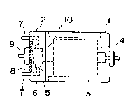
motor 1. Fur-ther, in Fig. 1, the reference numeral 1 designates
a motor body; 3, a field magnet; 4, a coil; 7, input terminals;
8, a PTC thermistor B according to the present invention; and 10
a commutator.
The PTC thermistor C is a square chip-shaped one formed on
the basis of the foregoing proposal and has silver electrodes at
its opposite surfaces. As shown in Fig. 3, a groove is formed in
14
:: ~
- :
: .
~73~5
the inside of a motor casing 2 so -tha-t a PTC thermistor 8a is
incorporated in the groove. Further, the PTC thermis-tol C is
electrically connected between an input terminal and a phosphor-
bronze p}.ate connected -to a brush 5 of the mo-to:r 1. Further, in
Fig. 3, the reference numerals 1 10 e~cept 8 clesi~nate portions
-the same as or corresponding to those of Fig. 3, and -therefore
the explanation -thereof is omitted.
The PTC thermistors were set in a constant-temperature oven
(not shown) and the response performance the:reof was measured in
a state that the motor was locked and under three conditions,
that is, the temperature/voltage c.onditions of -30CJlOV,
25C/14V, and 80C/14V. Table l shows the measurement results.
The conditions were set on the estimation of temperature/voltage
fluctuations in ordinary cars.
Table 1
~ - , , , :
I I Response time t~(sec~ I Limit current Io (A) I
,
I 1 30C~ I 25C/ I 80C/ 1-30C/ I 25C/ I 80C/ i
I I10~ 114V I14V I lOV I 1~- 1 14V
I I I I I I
I PTC I 53 1 lO I 2.5 1 0.24 1 0.14 1 0.12 1
I thermistor A
l PTC I 21 1 5 1 1.6 1 0.26 1 0.15 1 0.12 1
I thermistor B
I PTC ~ 18 1 4 1 1.2 1 0.34 1 0.22 1 0.16 1
I thermistor C
As shown in Fig. 6 5 the response time in Table 1 means time
tl(ses) required for limitin~ a circui.t current to lA and the
limitation current value in the same table means a stable dark
: ~ current Io(A) after current limitation.
: It is found from Table 1 that in each of the conditions, the
response time of the PTC thermistor C, that is, -the square chip
~ .
~:~ 15
:
.
. : . ' : -'': ' -
-: . : . ,
- - : ' ' :
:, :
~3~L~5
formed by us.ing the previously proposed ma-terial of high-
dielectric strength and low-resistance is the shortest and ttle
response -time of the PTC thermis-tor A is -the lollges-t. This is,
because -the volume of the basic body of -the PTC thermistor A is
about 30% as large as each o-f -the PTC thermistors B and C and
hence the heat cnpaci-ty of the basic body of` the PTC thermis-tor A
is small, i-f the resistance value, that is, the heat value, is
the same, the temperature of the PTC thermistor A rises easil~
and the PTC thermistor A is apt to be subjected to heat coupling
with the phosphor-bronze plate. Further, this is because -the PTC
thermistor A is mounted on the printed substrate separated ~rom
the motor, and there is no e~fect in heat coupling with the motor
and the heat environment in the surrounding of the thermistor A
directly contacts with the air, so that the rate of temperature
rising of the thermistor A is the slowest~ In the PTC thermistor
B, on the other hand, the heat capacity thereo~ is the same as
that of the PTC thermistor A, while it takes a value near that of:
the PTC thermistor C because of the heat coupling effect owing to
$he incorporation.
Further, the expansion o~ the responss ti.me relative to a
fluctuation of temperature/voltage is smaller than that of the
PTC thermistor A. This is because an e-ffect due to existence of
heat coupling and a difference in heat environment. Reduc-tion o~
expansion of the response time relative to a fluctuation of tem-
perature~voltage is one of the: conditions required particularly
from the fi ld of car industries.
Further, the limitation current value of the PTC thermistor
C is the lnrgest and therefore the power loss is the largest,
~hile that of the PTC thermistor A is the smallest. Tha limita-
: 16
~ ~73~S
-tion current value o the PTC thermistor B is subs-tantially equal
to that of the PTC -thermistor A although i-t is slightly higher
than that of the PTC thermistor A.
Thus, according -to the method of -the present invention, -there
are bo-th effec-ts that the response performance o~ the PTC ther-
mis-tor A of the conventionally widely used system is improved,
and that the powe.r loss after current limi-tal;ion as seen in the
PTC thermistor C according to the previously proposed method ls
reduced.
(Example 3)
The thermistor formed in Example 1 was circumscribecl onto
the motor casing of the motor used in Example 2 as shown in Fig.
7. That is, a PTC thermistor B 8 was circumscribed onto a motor
casing 2 so as to be disposed axis-symmetrically with respect to
the extension axis of a shaft 9 of the motor 1 and electrically
connected between an input terminal 7 and a phosphor-bronze plate
6 connected to a brush of the motor. A~ter the circumscription,
the doughnut-shaped PTC thermistor 13 was sealed with silicon
resin (not show) having a high heat radiation property so as to
stabilize the thermistor. The PTC thermistor circumscribed type
motor was formed as described above, and the respQnse time and
the limitation current value were measured in the same manner as
in Example 2. Table 2 shows the measuremen-t results.
Table 2
I I Response time t~sec) I Limit current Io ~A) I
I l-30C/ 1 25C~ I 80C/ l-30C/ I 26C/ I BQ~C/ I
l I lOV I 14V I 14V I lOV I l~V I l~V
I PTC 1 2~ 1 6 1 1.9 1 0.25 1 0.14 1 0.12 1
I th~rmistor B
-- L I, , ... _.__ I . ... 1._._ .__ I I
lq
: ~ ~ : . .
', . :
' - ' : :
.
Z~7~
It is found from Table 2 -that although -the response time is
slightly long in comparison with the incorporation -type, for
e~ample, in the case of the PTC thermistor B of` Example 2, the
l.imitation current value is further reduced to -thereby reduce a
power loss.
As described above, according -to the present invention, a
PTC thermistor is formed into a doughnut shape and an opening
thereof is inserted on-to a shaft of a small-si~ed DC motor or an
extension thereof so that the PTC thermistor is incorporated in
or circumscribed on a motor casin~ so as to make the plate sur-
face of the PTC thermistor substantially perpendicular -to -the
shaft. Further, the PTC thermistor is provided betwèen input
terminals of the motor. There~ore, the improvement of the two
characteristics are attained such that the response performance
of -the PTC thermi~tor is improved in comparison with the conven-
tional case where the PTC thermistor is pro~ided on the control
substrate and that the power loss after current limitation is
reduced~in'comparison with the conventional case where the pLate-
like thermistor is incorporated.
:: :
~ 18
~: :
:
,