Note : Les descriptions sont présentées dans la langue officielle dans laquelle elles ont été soumises.
W~ 92/10016 PC1'/US91/0~9~7
_ 1 _
IdYGB°fThTG COPfl,'ROIa k'OI2 ~'FIERGY
P4ANAGEI~NT 13~'~TEP2
Background of the Tnvention and prior Art
This invention relates generally to
electrical distribution systems and specifically
to a system for incorporating energy management .
circuit breakers (EMCBs) in new or existing
panelboards.
It is common practice to use so-called
EMCBs for remotely controlling the opening or
closing of one or more branch electric circuits
in response to an appropriate command signal.
Command signals may be developed from any number
of different controlling devices such as dry
contact switches, low voltage switch contacts,
power line carrier networks, thermostatic
controls, radio frequency devices, etc. The
controlling device supplies input signals to an
interface device which, in turn, processes the
input signals and develops driving power for
operating a circuit breaker t:o an open or a
closed position. The interface device may also
be capable of indicating the breaker status on a
remote panelboard or the like. Such systems may
be used to preprogram a plurality of circuit
breakers to operate lighting systems, security
systems, manufacturing systems and the like.
EMCBs generally comprise a conventional
circuit breaker with a drive mechanism attached
thereto for opening and closing the breaker
contacts, generally through the mechanism of an
electric motor that is controlled by a control
device. An EMCB is generally larger than its
mechanical circuit breaker counterpart and
requires mare wiring space in the panelboard
CA 02073985 2002-O1-10
- 2 -
enclosure. The generally cramped quarters in the enclosure
and the need to run low voltage control lines in proximity to
the electrical power lines presents a major problem in
developing a system that can be used with an existing
panelboard installation. Another difficulty is that
different manufacturers and users have particular
requirements for the control mechanisms that interface
between the controllers and the EMCBs. It is therefore
desirable to provide a system that is modular in construction
to enable its use with different types of control units.
Accordingly it is desirable to provide a novel EMCB
panelboard system, and an EMCB panelboard system that is
retrofittable on existing panelboards.
It is also desirable to provide a modular EMCB
panelboard system that may readily utilize different control
units and EMCB breaker types, and to provide a retrofittable
EMCB panelboard system that minimizes wiring clutter in the
panelboard enclosure.
Summar~r of the Invention
A retrofittable EMCB panelboard system can be provided
which comprises a bus way that is supportable alongside a
plurality of circuit breaker positions in a panelboard by
means of an interface module and one or more EMCBs. The
interface module can be connected to the power bus in the
panelboard and can include a power supply for developing
power for the control units and EMCB operating mechanisms. A
control module is designed that can couple with the interface
module and to intercouple with a plurality of connectors that
are incorporated in the bus way and positioned adjacent
respective circuit breaker positions in the panelboard. Low
voltage control wires may be coupled to the control module
via printed circuit boards and interconnecting connectors.
The entire system is capable of plug-in connection without
the use of tools. The interface module power supply and
control module occupy a number of breaker spaces and may be
positioned at any location within the panelboard with the bus
CA 02073985 2002-O1-10
- 3 -
way being positioned at either the right or left hand side,
or both.
In accordance with another aspect of this invention
there is provided for use with an electrical panelboard
having power terminal means and defining a plurality of
circuit breaker positions adjacent the power terminal means;
interface module means supportable on the side panelboard and
including thereon power supply means for developing operating
potential from the power terminal means; control module means
mounted to the interface module means and being supplied with
operating potential therefrom; and bus means including
connection means adjacent one of the circuit breaker
positions for intercoupling the interface module means to a
control device occupying the one circuit breaker position.
In accordance with another aspect of this invention
there is provided an electrical panelboard having power
terminals and defining a plurality of circuit breaker
positions adjacent to the power terminals: an interface
module supported on the panelboard; power supply means in the
interface module for developing operating potential from the
power terminals; a control module mounted to the interface
module and being supplied with the operating potential; a bus
including individual connectors adjacent corresponding ones
of the circuit breaker positions for intercoupling the
interface module to one or more remotely controllable circuit
breakers occupying respective ones of the circuit breaker
positions, the bus being supported by the interface module
and the remotely controllable circuit breaker; and the
interface module including a first connector for coupling the
interface module to the control module and a second connector
for coupling the interface module to the remote control
circuit breaker.
In accordance with another aspect of this invention
there is provided a lighting control and energy management
system adapted for use with an existing panelboard having a
plurality of circuit breaker positions accessible to a power
bus comprising: a snap on device including a power supply, a
control unit and a first connector; a bus way having a second
CA 02073985 2002-O1-10
- 3a -
connector at one end for mating engagement with the first
connector and a plurality of third connectors adjacent
respective ones of the circuit breaker positions; a control
device occupying one of the circuit breaker positions and
including a fourth connector mating with the adjacent one of
the third connectors, and a power stab for coupling to the
power bus; and the bus way being positioned by the second
connector and the third connectors.
Brief D ~ ri~tinn pf In Drawin~~
The invention and its various aspects will be
understood by reading the following specification in
conjunction with the drawings, in which:
Figure 1 is a simplified block diagram of a
panelboard incorporating the invention;
Figure 2 is a perspective of an interface module
base;
Figure 3 is a side view of an interface module
cover;
Figure 4 is a top view of the interface module
cover of Figure 3;
Figure 5 is a perspective view of an assembled
control module cover and base;
Figure 6 is a side view of the control
'dV 0 I2/ 10016 PCT/ L'S91 /0895'
4 --
Figure 7 is a partial cutaway view of
the interface module and control unit mounted to
the bus way; and
Figures 8 and s are views of a terminal
box caver.
Describtion of the Preferred Embodiment
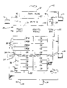
;Figure 1 illustrates a panelboard
incl,ud~ing an enclosure 10 in which an input
conduit 12 is provided for housing the main inpu~
power lines from a source (not shown) and a
plurality of output conduits 14 for distributing
power to~various circuits or branches (also not
shown). A pair of maunting supports l6 and 18
are parallelly disposed on each side of enclosure
and mounted thereto by a plurality of suitable
fasteners 17. The main power buses for providing
electrical power to the various branch circuits
are not illustrated by are well known and
normally extend between mounting supports 16 an
18. A main circuit breaker 20 is shown. A
plurality of circuit breakers 22, of conventional
design, are shown in various locations on the
panelboard. It will be appreciated by those
skilled in the art that the panelboard defines a
plurality of circuit breaker positions (actually
two parallel rows of circuit breaker positions)
in which an individual circuit breaker is
installed by any conventional means. One end of
the circuit breaker is generally mechanically and
electrically coupled to one of the power rails by
means of a suitable spring type connector (not
shown) and, by means of a screw terminal
connection, to a circuit wire that extends to the
particular circuit being protected by the circuit
breaker. An interface module assembly 24 is
fVO 92/10016 PCT/1JS91/08957
- 5 - 207305
just below main circuit breaker 20. Interface
module 24 includes a power supply 26 and supports
a control module 29 that includes a terminal box
30. A bus way 37 extends along mounting support
16, but as will be explained, is not physically
mounted thereto. The bus way includes lip
portions that straddle raised portions of
mounting support 16 for approximate location
purposes. The bus way is secured in position by
the interface module and one or more of the EMCBs
32, four of which are shown in installed
position. The bus way 37 supports a plurality of
connectors--34 (only one of which is shown in
solid lines since the connectors are beneath the
EMCBs 32) which are connected to a printed
circuit board (not shown). The bus way also
includes a pair of mufti-pin connectors 36 (one
of which is visible, the other being located
beneath the power supply 26) which are
electrically coupled to the various connectars
36. As has been briefly discussed, the bus way
37 may be positioned on either side of the
panelboard since the connectors 36 are
interchangeable. The interface module 24 may
also be mounted at the bottom of the panelboard
as well as the top. As previously discussed, two
bus ways may be used with a single interface
module. In the embodiment illustrated, the
interface module displaces six breaker positions
in the panelboard. It should also be apparent
that both EMCBs and conventional circuit breakers
may be sued together in the panelboard as the
system requirements dictate. This is an
important feature of the invention since it
enables existing panelboards to be retrofitted
with EMCBs with a minimum of wiring. As will be
eavo ~ZO~oo~6 ~crius~aiog~s~
20739~~ - s -
seen, the connections between the panelboard
power bus and the interface module, the
connections between the interface module and the
power supply and the control module (including
the termination box), and the EMCBs are provided
by printed circuit boards and connectors with the
result that there are not extraneous wires that
need to be carefully positioned within the
panelboard enclosure. Thus the possibility of
contact.between the control wires and the
electrical power lines in the panelboard is
minimized. The EMCBs include a mating connector
that is mourited~for limited movement parallel to
the circuit breaker positions so that connector
34 may be readily engaged when installing the
EMCB. The connector 36 and one or more of the
COnneC'tOrS 34 serve to position and support bus
way 37 adjacent to the panelboard.
Figures 2, 3, 4 and 7 show the general
construction of an interface module housing
constructed in accordance with the invention.
Bpeeifically, a base 40 and cover 54 are formed
of plastic with the base 40 having a pair of
upstanding ribs 48 which straddle the phase
barriers in the enclosure and define open spaces
that enable the connection of power stabs that
are mounted to the printed circuit board (neither
shown) in the interface module to engage
appropriate power rails in the panelboard. A
plurality of upstanding ledges 50 are formed
about the periphery of base 40 for supporting an
interface module printed circuit board 73
(Figure 7). A pair of apertures 44 and 46 are
symmetrically located at the.ends of base 40 for
enabling a multi-pin connector 80 (Figure 7) to
extend from the printed circuit board to the
W~ 92/30016 PCT/US91/089; i
- 7 - 20'~3~85
bottom of interface module base 40. A pair of
snap type connection devices 39 are illustrated
for engaging appropriate apertures in the
mounting supports l6 or 18 of the panelboard 10
for securing the interface module 24 to the
panelboard without the need of fasteners. The ,
base 40 includes cut out rectangular portions 49
at its lower edge for enabling snap fits with
tangs 59 of the corresponding legs 58 that depend
from interface cover 54. The tangs 59 extend
through the side apertures 59 in the base of
interface module 40 and engage the underside
thereof. Cut out-portions 52 are cantilevered in
the base of the interface module 40 for
captivating the depending lecJs 58 when the tangs
59 are engaged. The cover 54 includes a cut out
56 for enabling access to another connector 84
(Figure 7) which is mounted on the obverse side
of the printed circuit board of the interface
module. As shown in Figure 7, a transformer 58A
and one or more electrical components such as
capacitor 58$ are mounted on printed circuit
board 73 and within cover 54.
Figures 5 and 6 show a control module
28 having a base 62 and a cover 64, which the
perspective of Figure 5 illustrating cover 64 in
position on base 62, and with Figure 6
illustrating the side view of cover 64. The
control module base 62 is attached tot he cover
64 by means of a plurality of depending legs 66
in the cover having tangs 68 that engage the
underside of base 62 by means of a plurality of
rectangular slots 69 formed therein. As is seen
in Figure 7, control module 28 includes means for
supporting a number of printed circuit boards
(61,63,75) therein as well as various electronic
WO 92/10086 PCT/US9i/089; i
20'~~9~5 - 8 -
apparatus (not illustrated) for enabling inputs
from various sensors to operate various drivers
(not shown) for operating the EMCEs. A suitably
shaped aperture 56A is partially visible in base
62 of control module 28 for enabling
interconnection between connector 85 an printed
'''circuit board 75 in the interface module 24 (see
Figure 7). Aperture 56A is arranged to overlie
the corresponding aperture 56 in the interface
module cover (Figure 4). Terminal box 30 formed
at the and of control module 28 includes
upstanding wall members that define circular
apertures 70 and 71 therein for enabling control
wiring to enter from either side of the control
module As will be seen with reference to Figures
7, 8 and 9, a cap 80 is adapted to be placed over
terminal box 30 and includes a panel for closing
off one of the apertures 70 or 71, depending upon
the point of entry of the control wiring.
Referring specifically to Figure 7, a
partially broken away view of assembled interface
module 24 and control module 28 is shown in
position on bus way 37. A pair of power stabs 72
(only one is visible) extend below the center of
interface modules 24 and are connected to printed
circuit board 73 that is supported within
interface module base 40. One of the power buses
74 in the enclosure 10 is shown in contact with
power stab 72. As illustrated, bus way 37
preferably comprises a pair of plastic
interlocking extruded channel members 41 and 42
which support a printed circuit board 43
therebetween. A connector 47 is supported on'
printed circuit board 43 and electrically coupled
thereto and engages a mating connector 80 that is
supported on printed circuit board 73 in
WO 92!10016 PCT/US91/08957
- 29°~39~5
interface module 24. The connector 47 extends
through aperture 46 in the base 40 of interface
module 24. Fus way 37 is in turn positioned
along mounting support 18 by suitable depending
members 82. control module 28 is bxoken away to
show printed circuit board 75 that supports
connector 85 which. engages connector 84 that is
mounted to the printed circuit board 73 in the
interface module 24. A plurality of screw-type
terminals 87 and 88 are provided for inter-
connecting the control wires to the various
conductive traces (not shown) on printed circuit
board 75. A cap 90, best illustrated in Figures
8 and 9, engages the upstanding walls of terminal
box 30 and includes a depending flap 92 that
covers one of the apertures 70 and 71. The other
aperture is coupled to a suitable conduit 29 as
illustrated in Figure 1 for housing the incoming
low voltage control wires. The cap 90 includes a
pair of oppositely disposed depending sides 94.
having tags 96 for engaging suitable recesses 97
in the inner wall surfaces of terminal box 30
(Figure 7).
It will be appreciated by those skilled
in the art that bus way 37 may be fabricated in
three sections with the two end suctions
including connectors 36 that are engaged with
appropriate conductive traces that interconnect
with the various connectors 34 and to the
interface module printed circuit board via
connectors 47 and 80. It will also be recognized
that the upper surface of the saver 64 of control
module 28 may have mounted therein
potentiometers, read out devices, or the like for
enabling operating adjustments or status
indications of the various devices controlled by
WU 92/10016 PCT/US91/08957
- 10 -
the control module. A11 such modifications are
believed well within the scope of the invention
and should be apparent to those skilled in the
art. The invention is to be limited only as
defined in the claims.