Note : Les descriptions sont présentées dans la langue officielle dans laquelle elles ont été soumises.
-1- 207422 1
APPARATU8 AND METHOD FOR AXIALLY
ALIGNING STRAIGHT OR CURVED CONDUITS
BACRGROUND OF THE INVENTION
The invention relates to an apparatus and method for
axially aligning conduits to permit "tack" welding of the
conduits prior to welding. In particular, the apparatus
and method are particularly adapted to axially align
conduits, irrespective of curvature, wall thicknesses and
respective diameters of the conduits to be welded.
In welding two conduits together in end-to-end relation it
is preferable to align the conduits axially to ensure a
good quality, even weld. Such axial alignment is
relatively easily achieved where the conduits to be joined
are of the same diameter, have the same wall thickness and
are straight at the end portions to be joined. However,
such axial alignment is difficult to achieve when the
conduits are curved as in the case of elbows, or where the
wall thickness or outside diameter of the conduits are
different as in the case of conduits supplied by different
countries.
Previously, the alignment of curved conduits or conduits
with differing wall thicknesses or outside diameters was
performed by welding lugs onto respective end portions of
the conduits to be joined and providing jacking bolts which
could be selectively tightened to align the conduits. The
joint could then be "tacked" and the jacking bolts removed
and the lugs cut off to permit full welding of the entire
joint. This however requires the complicated step of
welding the lugs onto the conduits and then cutting the
lugs off and grinding smooth the outside surfaces of the
- -2- ~74~2 1
conduits. This can be very time consuming and in some
cases is difficult to do due to space limitations in the
proximity of the conduits. In addition, some types of
steel such as Chrome steel cannot have lugs welded thereto.
s
Other inventors have sought to solve the problem of
aligning conduits, however, they have addressed the problem
of aligning straight conduits or conduits having a mitred
joint. For instance US patent No. 3,422,519 to Fehlman
discloses a lineup clamp for pipe. However the surfaces
for contacting the end portions of the pipe are spaced
relatively far apart which might render the device
difficult to use on curved portions of pipe.
US patent No. 3,920,232 to Clark discloses an apparatus for
aligning pipe ends which uses a hydraulic ram acting on a
pipe in a circular cradle to align two pipes to be joined
together. The apparatus thus appears to be intended for
use with pipes of a specific diameter and of the same
outside diameter and wall thickness.
US patent No. 3,467,295 to Watson discloses a clamping
means for pipes and fittings which has a first pipe contact
member and an extending arm having a screw member acting as
a second pipe contacting member. Considerable leverage is
applied to the extending arm to provide sufficient force on
the screw member to align the pipes. The extending arm
might limit the use of the apparatus only to applications
where there is sufficient distance for the arm to extend
between the two conduits to be joined.
US patent No. 3,944,202 to Dearman discloses a clamping
device for use in making mitred joints in pipe sections and
US patent No. 3,925,854 to McFadden discloses an alignment
clamp. Both of these devices are similar to the Watson
patent in that they both employ an extending arm and
require sufficient distance for the arm to extend between
the two conduits to be joined.
207 422 1
From the above prior art it can be seen that there is a
need for a device which permits alignment of conduits
having differing outside diameters and differing wall
thicknesses and/or a curved portion adjacent the portion or
part of the end portion to be joined.
8UNMARY OF THB INVBNTION
In accordance with the present invention there is provided
an apparatus for aligning conduits including pipes, pipe
fittings and the like prior to joining including first ring
means for removably encircling an end portion of a first
conduit to be joined and second ring means for removably
encircling an end portion of a second conduit to be joined
to the end portion of the first conduit. Connecting means
are provided for connecting the first and second ring means
together in axially spaced apart relation so that the ring
means are spaced apart sufficiently to permit joining of
the end portions of the conduits between the first and
second ring assemblies. The apparatus is also provided
with aligning means for axially aligning the end portions
of the first and second conduits, the aligning means being
disposed between the ring members and including a plurality
of adjustable contact surfaces for contacting respective
end portions of the first and second conduits. The contact
surfaces are moveable relative to each other to move the
first and second conduits into an axially aligned position.
Preferably, the apparatus includes respective first and
second arcuate members forming the ring means, the first
and second arcuate members being hingedly connected
together to permit the ring means to be removed from
respective conduits after welding.
Also preferably, the apparatus includes locking means for
locking the first and second arcuate members in a circular
form.
- ~4~ 2 07 4 22l
Also preferably, the connecting means includes a plurality
of bridge members extending between the first and second
ring means, the bridge members being spaced apart angularly
around the ring means.
Also preferably, the aligning means includes first and
second screws on each bridge member, the screws being
axially spaced apart, the first screw being adjacent the
first ring means and the second screw being adjacent the
second ring means, the first and second screws having first
and second contact surfaces respectively, the first and
second contact surfaces cooperating with respective bridge
members to extend generally radially inwardly of the ring
means to abut the first and second contact surfaces against
the end portions of the first and second conduits
respectively.
In accordance with another aspect of the invention there is
provided a method of aligning conduits including pipes,
pipe fittings, and the like prior to joining, the method
comprising the steps of:
a) removably encircling an end portion of a first
conduit to be joined with a first ring means;
b) removably encircling an end portion of a second
conduit to be joined to the end portion of the
first conduit with a second ring means;
c) connecting the first and second ring means
together axially and spaced apart sufficiently to
permit joining of the end portions of the
conduits between the first and second ring means;
d) moving a plurality of adjustable contact surfaces
disposed between the ring members, relative to
each other, the contact surfaces contacting the
~5~ 207422 1
first and second conduits to move the first and
second conduits into an axially aligned position.
Preferably, the method includes the step of extending first
and second screws radially inward of the ring means such
that first and second contact surfaces on the first and
second screws respectively abut the end portions of the
first and second conduits respectively.
BRIEF DE8CRIPTION OF THF DRA~ING8
Figure 1 is a perspective view of an apparatus according
to a first embodiment of the invention;
Figure 2 is a front view of the apparatus of Figure 1
shown in an open position, receiving conduits to
be joined together therein;
Figure 3 is a front view of the apparatus of Figure 1
shown in a locked position about the conduits to
be joined together;
Figure 4 is a side view of the apparatus of Figure 1 shown
mounted on two straight conduits to be joined
together;
Figure 5 is side view of the apparatus of Figure 1 shown
mounted on two curved conduits to be joined
together;
Figure 6 is a side view of the apparatus of Figure 1 shown
mounted on two straight conduits having different
wall thicknesses and outside diameters;
5 Figure 7 is a perspective view of an alignment member for
optional use with the apparatus of Figure 1.
DI8CLO8URE 207422 1
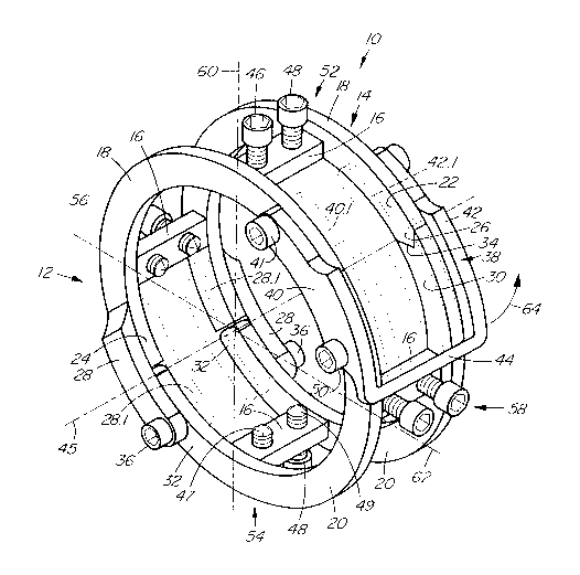
Referring to Figure 1, an apparatus for aligning conduits
such as pipes, pipe fittings and the like prior to joining
is shown generally at 10. The apparatus comprises first
and second ring assemblies 12 and 1~ connected together by
a plurality of bridge members 16.
The first and second ring assemblies 12 and 1~ each include
respective first and second arcuate members 18 and 20,
formed from CHT-100 High Tensile Steel. Such steel is
preferred over mild steel due to its hardness, strength and
ability to provide a degree of radial resilience in the
arcuate members. Generally, the first and second ring
assemblies are similar and therefore reference will be made
to the ring assemblies in general, it being understood that
reference to one ring assembly may also refer to similar
structure in the other.
The first ring assembly 12 includes a first arcuate member
18 having a first end portion 22 and a second end portion
2~. The first end portion has a pointed projection 26,
seen best on the second ring assembly 14, and the second
end portion has a connecting member 28, seen best on the
first ring assembly 12, which protrudes in a manner
following the arc of the first arcuate member 18.
The second arcuate member 20 has a first end portion 30 and
a second end portion 32, seen best on the second ring
assembly 14. The first end portion 30 has a receptacle 3~
for receiving the pointed projection 26 therein. The
pointed projection 26 and receptacle 34 thus act as
complementary engageable end portions for registering the
end portions in alignment to maintain respective ring
assemblies in a generally circular form.
The second end portion 32 is pivotally connected to the
connecting member 28 by a bolt 36. The first and second
~7~ 207422 1
arcuate members 18 and 20 are connected together by the
connecting member 28 and the bolt 36 such that they are
coplanar.
It will be appreciated that the bolt is of the type having
a shank with an unthreaded portion immediately adjacent the
head and a threaded portion immediately adjacent the
unthreaded portion. The threaded portion of the bolt is
received in a complementary threaded opening (not shown) in
the second end portion 32 such that travel of the bolt into
the second end portion is limited, to permit the unthreaded
portion of the shank to act as a pivot pin about which the
connecting member 28 can pivot as shown in Figure 2.
Furthermore it is preferred that the threaded portion of
the shank not project into the region between the first and
second ring assemblies to permit easy access therebetween
with joining equipment such as a welding rod. The threaded
portion of the bolt is tack welded to the second end
portion 32 such that the bolt is rigidly connected to the
second end portion to prevent inadvertent loss of the bolt.
Referring to Figures 1 and 2, the apparatus further
includes a locking member shown generally at 38, for
locking the first and second arcuate members together, in
circular arrangement. Referring to Figure 1, the locking
member is generally U-shaped and has first and second side
portions ~0 and 42 which are connected together by a cross
member 44. Generally, the first and second side portions
are similar and therefore only the first side portion will
be described, it being understood that the second side
portion is similar to the first side portion.
Referring to Figure 2, the first side portion 40 is
generally arcuate in shape and is pivotally connected to
the first end portion 22 by a bolt ~1 similar to the bolt
36 described above. Bolt 41 is welded to the first end
portion 22. The side portion 40 is provided with a recess
51 which projects transversely of the side portion 40 and
_ -8- ~0~422 1
is operable to receive an unthreaded portion (not shown) of
a bolt 50 mounted on the first end portion 30 of the second
arcuate member 20. Bolt 50 is welded to the first end
portion 30.
In Figure 2, the locking member is shown in an unlocking
position wherein the first and second arcuate members are
operable to pivot relative to each other. In Figure 1 the
locking member is shown in a locking position wherein the
bolt 50 is received within the recess 51 and the first and
second arcuate members 18 and 20 are prevented from
relative pivotal movement.
The first and second side portions 40 and ~2 of the locking
member 38 are held in spaced apart relation by the cross
member ~ such that the respective first end portions 22
and 30 of the first and second arcuate members respectively
of each ring assembly are disposed between the first and
second side portions ~0 and 42 and are held against axial
spreading by the side portions. Thus the first end
portions 22 and 30 are held between the side portions ~0
and ~2 of the locking member 38 while the cross member ~4
extends across and over the first and second ring
assemblies 12 and 1~. This provides a relatively rigid
connection of the first end portions 22 and 30 of the ring
assemblies. The locking member 38 thus acts as locking
means for locking the first and second arcuate members 18
and 20 in a circular form.
Referring to Figure 1, the bridge members 16 are connected
between respective first and respective second arcuate
members 18 and 20 and serve to connect together the first
and second ring assemblies 12 and 14 in parallel spaced
apart relation. The first and second circular assemblies
12 and 14 thus lie in respective spaced apart planes and
are centred on a common axis ~5.
-9- 207422 1
In the embodiment shown, there are four bridge members
equidistantly spaced about the circumference of the ring
assemblies. In particular, in this embodiment, the bridge
members are spaced apart by 90 degrees. The apparatus thus
includes a plurality of bridge members extending between.
the first and second ring assemblies, the bridge members
being spaced apart angularly around the ring assemblies.
The bridge members 16 are similar to each other and
therefore only one will be described, it being understood
that the remaining bridge members are similar.
Referring to Figure 3, in the embodiment shown, the
apparatus includes bridge members at a top portion 52, a
bottom portion 54, a first side portion 56 and a second
side portion 58 thereof. Each of the bridge members is
situated between the ring assemblies as close as possible
to the common axis 45 to reduce any tendency of the ring
members to deform when the apparatus is in use.
Referring to Figure 1, bridge member 16 at the bottom
portion 54 extends between respective second arcuate
members 20 and has first and second screw members 46 and
48, having respective first and second contact surfaces ~7
and 49. The screw members 46 and 48 are threaded in the
bridge member in parallel spaced apart relation, the screw
members being spaced apart in a direction parallel to the
common axis 45 of the first and second circular assemblies
12 and 14, the first screw member being adjacent the first
ring assembly and the second screw being adjacent the
second ring assembly. The first and second screw members
~6 and 48 thus extend radially of the ring assemblies and
are operable to be rotated to move the first and second
contact surfaces 47 and 49 respectively radially towards or
away from the common axis 45.
The bridge members at the top and bottom portions 52 and 54
permit their first and second screw members to extend
radially along a first axis 60 and the bridge members at
- -lO- 207422 1
the first and second side portions 56 and 58 permit their
first and second screw members to extend radially along a
second axis 62.
OPERATION
Referring to Figure 1, the apparatus 10 is rendered ready
for use by lifting the locking member 38 in a direction
shown by arrow 6~ such that the locking member 38 is clear
of the second arcuate member 20. Referring to Figure 2,
the locking member 38 is shown out of engagement with the
bolt 50 and clear of the second arcuate member 20.
Still referring to Figure 2, the first and second arcuate
members 18 and 20 are then hinged outwards relative to each
other into the position shown in Figure 2, wherein
respective end portions of first and second conduits to be
joined can be inserted between the first and second arcuate
members 18 and 20. For illustrative purposes, the conduits
are shown generally at 66 in Figure 2.
Referring to Figure 3, the first and second arcuate members
18 and 20 are then closed upon the conduits 66 until the
projection 26 is received within the receptacle 3~. The
end portions of the first and second arcuate members 18 and
20 are thus registered in alignment to maintain respective
ring means in a generally circular form. The locking
member 38 is then rotated to engage the recess 51 with bolt
50. Bolt 50 and recess 51 cooperate to secure the locking
member 38 in locking engagement wherein the first and
second arcuate members 18 and 20 are held in the circular
form. As the recess 51 extends transversely of the side
portion 40, forces between the recess 51 and the bolt 51
tend to act perpendicular to the recess thereby maintaining
the locking member 38 in engagement.
Referring to Figure 4, the apparatus is installed on the
end portions of two straight conduits to be joined such
- -11- 207422 1
that the first ring assembly 12 removably encircles a first
end portion 70 of a first conduit to be joined and the
second ring assembly removably encircles a second end
portion 72 of a second conduit to be joined to the end
portion of the first conduit.
It will be appreciated that the first end portion 70 has a
first longitudinal axis 74 and the second end portion has
a second longitudinal axis 76 and that the first and second
axes 74 and 76 are preferably aligned and coincident with
common axis 45 before the conduits are joined together, to
ensure a good quality joint.
Alignment of the first and second axes is effected by
rotating the first and second screws 46 and 48 on each
bridge member 16 such that the first and second contact
surfaces 47 and 49 cooperate with respective bridge members
to move relative thereto. The first and second screws
extend generally radially inwardly of the ring assemblies
to abut respective first and second contact surfaces 47 and
49 against the end portions 70 and 72 of the first and
second conduits respectively near a join line 73 formed by
the abutment of the first and second conduits axially
together. The screws 46 and 48 may then be selectively
rotated to move the first and second conduits into an
axially aligned position. The screw members and contact
surfaces act as aligning means for axially aligning the end
portions of the first and second conduits, the aligning
means being disposed between the ring assemblies.
With the end portions 70 and 72 in alignment, the task of
joining the end portions together can be performed. If the
conduits are to be joined by welding, the apparatus
provides easy access to the joint to be welded, in areas
bounded by the ring assemblies and the bridge members such
as shown generally at 80 in Figure 4. It will be
appreciated that in the embodiment shown there are four
such areas equally spaced and separated by the bridge
-
-12- 207422 1
members. This permits a welder to "tack" weld the joint in
at least four locations around the joint, or alternatively
a longer root bead weld can be made in this area.
Furthermore as the evenly spaced bridge members place the
contact surfaces of the screw member~ evenly around the end
portions of the conduits, electrical grounding of the
conduits is evenly distributed which acts to prevent "arc
blow" due to welding.
After "tacking" the joint, the apparatus can then be
removed from the conduits by unlocking the locking member
38 and hinging the apparatus open into the position shown
in Figure 2. The apparatus can then be removed from the
conduits and welding of the entire joint can then be
performed without hinderance of the apparatus.
It will be appreciated that the first and second ring means
each include respective first and second arcuate members
hingedly connected together to permit the ring means to be
removed from respective conduits after welding and that the
bridge members act as connecting means for connecting the
first and second ring assemblies together in axially spaced
apart relation so that the ring assemblies are spaced apart
sufficiently to permit joining or "tacking" of the end
portions of the conduits between the first and second ring
assemblies.
ALTER~IATIVE U8E8
Referring to Figure 5, in one use of the apparatus, the
apparatus is mounted on two oppositely curved conduits 82
and 84. As the first and second screws ~6 and 48 are
mounted on the bridge members 16 the first and second
contact surfaces ~7 and 49 are disposed in close proximity
but spaced apart sufficiently to provide good contact on
the respective end portions of the conduits to be joined.
The first and second contact surfaces ~7 and 49 contact the
end portions of the conduits immediately adjacent any weld
-13- 207422 1
bevel on the conduits such as shown at 86 and 88 in Figure
5. As the contact surfaces ~7 and 49 are in close
proximity to each other, curved conduits such as those
shown in Figure 5 can be aligned and "tack" welded together
easily and without difficulty.
Referring to Figure 6, in an alternative use of the
apparatus, the apparatus is used to align and join together
conduits 200 and 202 of slightly different outside diameter
and different wall thicknesses. This has particular
advantages where a particular job involves connecting
together conduits supplied by a plurality of countries
which supply conduits having differing wall thicknesses and
outside diameter. The apparatus is mounted to such
conduits in a manner similar to that described above. As
the first and second screws 46 and 48 are mounted on the
bridge members 16 the first and second contact surfaces ~7
and ~9 are disposed in close proximity but spaced apart
axially sufficiently to provide good contact on the
respective end portions of the conduits to be joined.
Furthermore, the first and second screws 46 and ~8 are
rotated such that the first and second contact surfaces ~7
and ~9 are at different distances from the common axis ~5,
whereby the difference in outside diameter is accommodated
and alignment respective conduit axes 20~ and 206 is
achieved by further rotation of the screws as required.
ALTBRNATIVE8
Referring to Figure 1, in an alternative embodiment,
particularly adapted for aligning large diameter pipes,
there is a connecting member 28.1 (shown in broken outline)
similar to connecting member 28, on an inside portion of
each of the first arcuate members 18. The bolt 36 extends
between the connecting members 28 and 28.1 and is welded to
each member 28 and 28.1. The bolt extends through an
opening (not shown) in the second arcuate member to provide
the required pivotal connection of the first and second
- -14- 207422 1
arcuate members. The use of connecting members 28 and 28.1
provides extra strength to the apparatus which is
advantageous where large diameter and hence heavy pipes are
to be joined.
In addition, the locking member is reinforced for use with
large diameter pipes in that it is provided with inner side
portions 40.1 and 42.1 parallel and spaced apart from side
portion 40 and ~2 respectively. The first end portion 22
of the first arcuate member 18 and the first end portion 30
of the second arcuate member 20 are received between the
side portions 40 and 40.1 and 42 and 42.1 respectively.
The bolt 41 extends between the side portions 40 and 40.1,
through an opening (not shown), in the first arcuate member
18. The bolt is welded to the side portions ~0 and 40.1
but is free to pivot within the opening in the first
arcuate member to provide the necessary pivotal movement of
the locking member ~4 relative to the ring assemblies.
Bolt 50 remains as described above when the inner side
portions 40.1 and 42.1 are employed. The use of the inner
side portions prevents buckling or twisting of the end
portions 22 and 30 relative to each other and maintains the
ring assemblies in a circular form when under loads imposed
by tightening the screw members 46 and ~8. The inner side
portions 40.1 and 42.1 are particularly useful when the
apparatus is used on large diameter pipes.
Referring to Figure 7, an additional aligning member for
the apparatus shown in Figures 1-5 is shown generally at
100. The aligning member includes a generally U-shaped
member 102 which is fitted over a portion 104 of the first
or second arcuate member of Figures 1-5. The U-shaped
member 102 has first and second leg portions 106 and 108
respectively, the second leg portion 108 being longer than
the first leg portion 106. A conventional bolt 110 extends
between the first and second leg portions and acts to
secure the U-shaped member 102 to the portion 104. It will
be appreciated that the U-shaped member may be installed on
- -15- 207 422 1
the first or second arcuate member at any desired location
and is therefore removably connectable to at least one of
the ring assemblies.
The second leg portion 108 of the U-shaped member has a
distal end portion 112 having a threaded opening 11~ which
extends radially relative to the common axis ~5 shown in
Figure 1 when the U-shaped member is installed on an
arcuate member. A bolt 116 having a third contact surface
118 is in threaded engagement with the threaded opening 11~
and is operable to be rotated to move the third contact
surface 118 relative to the U-shaped member and hence
relative to the ring assembly to which the U-shaped member
is attached. The third contact surface is thus operable to
move radially inwards and outwards relative to the common
axis ~5 of Figure 1 and therefore is operable to provide a
further contact point to assist in aligning the conduits
prior to "tacking". It will be appreciated that any number
of additional alignment members may used in conjunction
with the apparatus of Figures 1-5 to permit movement of the
end portions of the conduits in any direction radial to the
common axis 45.
The alignment members are particularly useful where the
radius of the conduits to be joined and hence the radii of
the ring assemblies is relatively large. In particular, the
apparatus is useful in aligning large diameter, thin-walled
stainless steel pipe as the alignment members can be used
to provide enough force to deform the wall of the pipe at
a particular location to permit easy alignment of the walls
of the pipes to be joined.
It will also be appreciated that the additional alignment
members may be installed on the ring assemblies such that
the third contact surfaces 118 are located between the ring
assemblies or such that the third contact surfaces are
located outside of the ring assemblies, thus providing
versatility in choosing additional contact points for
-16- 207422 1
applying additional alignment forces to align the conduits
to be "tacked" or joined.