Une partie des informations de ce site Web a été fournie par des sources externes. Le gouvernement du Canada n'assume aucune responsabilité concernant la précision, l'actualité ou la fiabilité des informations fournies par les sources externes. Les utilisateurs qui désirent employer cette information devraient consulter directement la source des informations. Le contenu fourni par les sources externes n'est pas assujetti aux exigences sur les langues officielles, la protection des renseignements personnels et l'accessibilité.
L'apparition de différences dans le texte et l'image des Revendications et de l'Abrégé dépend du moment auquel le document est publié. Les textes des Revendications et de l'Abrégé sont affichés :
| (12) Brevet: | (11) CA 2075106 |
|---|---|
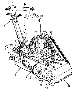
| (54) Titre français: | MACHINE DE PLANAGE POUR PLANCHERS DE BOIS |
| (54) Titre anglais: | PLANING MACHINE FOR WOOD FLOORS |
| Statut: | Périmé et au-delà du délai pour l’annulation |
| (51) Classification internationale des brevets (CIB): |
|
|---|---|
| (72) Inventeurs : |
|
| (73) Titulaires : |
|
| (71) Demandeurs : |
|
| (74) Agent: | SMART & BIGGAR LP |
| (74) Co-agent: | |
| (45) Délivré: | 2004-07-13 |
| (22) Date de dépôt: | 1992-07-31 |
| (41) Mise à la disponibilité du public: | 1994-02-01 |
| Requête d'examen: | 1999-07-26 |
| Licence disponible: | S.O. |
| Cédé au domaine public: | S.O. |
| (25) Langue des documents déposés: | Anglais |
| Traité de coopération en matière de brevets (PCT): | Non |
|---|
| (30) Données de priorité de la demande: | S.O. |
|---|
The planing machine for wood floors includes a truck
with retractable front wheels and with a rear wheel which is
provided with means for varying the attitude of the machine
when the direction of motion changes; a treatment head which
is provided with two abrasive paper supporting rollers which
rotate in different directions, is articulately supported by
the truck and is provided with a portion which is in contact
with elastic positioning and contrast means; an aspirator
which conveys the wood dust into a collecting bag; and at
least one electric motor which drives the rollers which
support the abrasive paper and the aspirator.
Note : Les revendications sont présentées dans la langue officielle dans laquelle elles ont été soumises.
Note : Les descriptions sont présentées dans la langue officielle dans laquelle elles ont été soumises.
2024-08-01 : Dans le cadre de la transition vers les Brevets de nouvelle génération (BNG), la base de données sur les brevets canadiens (BDBC) contient désormais un Historique d'événement plus détaillé, qui reproduit le Journal des événements de notre nouvelle solution interne.
Veuillez noter que les événements débutant par « Inactive : » se réfèrent à des événements qui ne sont plus utilisés dans notre nouvelle solution interne.
Pour une meilleure compréhension de l'état de la demande ou brevet qui figure sur cette page, la rubrique Mise en garde , et les descriptions de Brevet , Historique d'événement , Taxes périodiques et Historique des paiements devraient être consultées.
| Description | Date |
|---|---|
| Le délai pour l'annulation est expiré | 2005-08-01 |
| Lettre envoyée | 2004-08-02 |
| Accordé par délivrance | 2004-07-13 |
| Inactive : Page couverture publiée | 2004-07-12 |
| Inactive : Taxe finale reçue | 2004-04-30 |
| Préoctroi | 2004-04-30 |
| Un avis d'acceptation est envoyé | 2003-11-25 |
| Lettre envoyée | 2003-11-25 |
| Un avis d'acceptation est envoyé | 2003-11-25 |
| Inactive : Approuvée aux fins d'acceptation (AFA) | 2003-11-06 |
| Modification reçue - modification volontaire | 2003-10-08 |
| Inactive : Dem. de l'examinateur par.30(2) Règles | 2003-04-08 |
| Lettre envoyée | 2003-03-11 |
| Exigences de rétablissement - réputé conforme pour tous les motifs d'abandon | 2003-02-27 |
| Réputée abandonnée - omission de répondre à un avis sur les taxes pour le maintien en état | 2002-07-31 |
| Lettre envoyée | 2002-03-12 |
| Inactive : Grandeur de l'entité changée | 2002-03-12 |
| Exigences de rétablissement - réputé conforme pour tous les motifs d'abandon | 2002-03-04 |
| Réputée abandonnée - omission de répondre à un avis sur les taxes pour le maintien en état | 2001-07-31 |
| Inactive : Dem. traitée sur TS dès date d'ent. journal | 1999-08-03 |
| Lettre envoyée | 1999-08-03 |
| Inactive : Renseign. sur l'état - Complets dès date d'ent. journ. | 1999-08-03 |
| Exigences pour une requête d'examen - jugée conforme | 1999-07-26 |
| Toutes les exigences pour l'examen - jugée conforme | 1999-07-26 |
| Lettre envoyée | 1999-02-11 |
| Exigences de rétablissement - réputé conforme pour tous les motifs d'abandon | 1999-02-02 |
| Réputée abandonnée - omission de répondre à un avis sur les taxes pour le maintien en état | 1998-07-31 |
| Demande publiée (accessible au public) | 1994-02-01 |
| Date d'abandonnement | Raison | Date de rétablissement |
|---|---|---|
| 2002-07-31 | ||
| 2001-07-31 | ||
| 1998-07-31 |
Le dernier paiement a été reçu le 2003-07-08
Avis : Si le paiement en totalité n'a pas été reçu au plus tard à la date indiquée, une taxe supplémentaire peut être imposée, soit une des taxes suivantes :
Veuillez vous référer à la page web des taxes sur les brevets de l'OPIC pour voir tous les montants actuels des taxes.
| Type de taxes | Anniversaire | Échéance | Date payée |
|---|---|---|---|
| TM (demande, 5e anniv.) - petite | 05 | 1997-07-31 | 1997-07-04 |
| Rétablissement | 1999-02-02 | ||
| TM (demande, 6e anniv.) - petite | 06 | 1998-07-31 | 1999-02-02 |
| TM (demande, 7e anniv.) - petite | 07 | 1999-08-02 | 1999-06-15 |
| Requête d'examen - petite | 1999-07-26 | ||
| TM (demande, 8e anniv.) - petite | 08 | 2000-07-31 | 2000-07-19 |
| TM (demande, 9e anniv.) - générale | 09 | 2001-07-31 | 2002-03-04 |
| Rétablissement | 2002-03-04 | ||
| Rétablissement | 2003-02-27 | ||
| TM (demande, 10e anniv.) - générale | 10 | 2002-07-31 | 2003-02-27 |
| TM (demande, 11e anniv.) - générale | 11 | 2003-07-31 | 2003-07-08 |
| Taxe finale - générale | 2004-04-30 |
Les titulaires actuels et antérieures au dossier sont affichés en ordre alphabétique.
| Titulaires actuels au dossier |
|---|
| OLGA BELLATI |
| FRANCESCO DEBIASI |
| Titulaires antérieures au dossier |
|---|
| S.O. |

