Note : Les descriptions sont présentées dans la langue officielle dans laquelle elles ont été soumises.
~ WO 92~t0644 2 0 7 ~ ~ 3 8 PCr/US91/09234
t
LAUNCH VEHICLE FOR Cu., lNU~U~i MINING APPARATUS
T~hn; r~ 1 Field
The present invention relates generally to
the art of mining and, more particularly to a launch
5 vehicle for an apparatus adapted for the continuous
mining of aggregate material, such as coal, in situ.
Backaro~n~l Qf the Invention
Coal, formed from 19~ ~ed and compressed
vegetable matter, is typically found in substantially
10 horizontal seams extending between sedimentary rock
strata such as limestone, sandstone or shale. Surface
and underground mining are the primary te- hn i qn~e used
to recover this coal.
Surface or strip mining involves the removal
15 of material, known as overburden, overlying a coal seam
so as to expose the coal for recovery. In recent
years, surface mining has gained prnmin~nce over
Undt!Lu.uu..d mining in the United States. This is due
to many factors including:
(a) the increased material moving capacity
of surface or strip mining equipment;
(b) lower costs for surface mining than
underground mining;
(c) the better safety record of surface
25 mining versus underground mining;
(d) the higher coal recovery percentage for
WO 92/l0644 2 0 7 5 6 3 8 PCr/US91/0923~
~ 2
extraction of mally coal reserves by surface mining.
Surface mining does, however, have its
limitations despite these cited advantages. The
primary limiting factor relates to the depth of the
5 overburden. Once the coal seam reaches a certain depth
below the surface, the amount of overburden that must
be removed to reach the coal simply makes strip mining
economically unfeasible.
When this occurs, large quantities of coal
10 may still remain in the ground. If rcr- i r recovery
of this coal is to be achieved, other mining methods
must be utilized. Underground mining application in
such an instance is, typically, very limited. This may
be due to a number of factors including the existence
15 of poor roof support conditions, the th;nn~cs of the
seam and/or the presence of insufficient quantities of
coal to warrant the large capital investments
characteristic of underground operations.
Due to these rnn~idr-rations, auger mining is
20 often used to recover coal following a strip mining
operation where the overburden becomes too costly to ~
rQmoVe. A large aUgQr is used to bore into the face of
the seam and recover the coal from beneath the
overburden. Advant~eollcly, auger mining is very
25 efficient providing more tons per man per day than any
other form of state of the art mining t~rhn; qu~c.
Auger mining may also be initiated quickly and requires
a relatively low capital expenditure when compared to
surface and underground mining. Auger mining has also
30 been found to date to be the best method to use in
relatively thin seams. Further, auger mining is safer
than both surface and underground mining. Thus, auger
mining may be used to effectively supplement a strip
mining operation and recover small coal deposits that
,. ,
~` ~
3 2~75~38
would otherwlse be left behlnd.
Auger mlnlng 18, however, also not wlthout lts
dlsadvantages. Auger mlnlng provldes a relatlvely low total
coal recovery. Coal recovery for the resource area being
augered 18 usually less than about 35%. Some of the lost
recovery ls due to the plllars of coal that are left standlng
to support the overburden between ad~acent auger holes. The
ma~orlty of the recovery shortfall, however, ls due to the
llmlted penetratlon depths achlevable wlth even state of the
art auger mlnlng equlpment .
More partlcularly, as penetratlon depths lncrease, a
greater number of auger fllghts are regulred to convey the
coal from the cuttlng head to the seam face for recovery.
Each fllght adds to the frlctlonal reslstance to the turnlng
of the auger through contact wlth the walls of the bore hole.
Addltlonally, the longer the strlng of auger fllghts, the
greater the welght of coal belng moved by the f llghts at any
one t lme . As a result, it should be appreclated that auger
power requlrements lncrease rapldly wlth the depth of auger
20 penet rat lon .
Due to the above conslderatlons, holes drllled by
conventlonal augurlng equlpment are usually only of a depth of
150 feet wlth 200 feet belng rarely attalnable. Of coarse,
any lncrease ln thls flgure 18 deslrable as lt would greatly
lmprove the coal recovery rate from a resource area.
A mlnlng system and method has been recently
developed to meet thls end. More partlcularly, thls system
74320-4
_ _ _ _ .. .. , . . , . . . _ _ .. _ . _ ..
2~75~38
and method ls dlsclosed 18 Unlted States Patent No. 5,112,111
lssued May 12 1992, entltled APPARATUS AND METHOD FOR
CONTINUOUS MINING and asslçJned to the asslgnee of the present
lnvent lon .
As best shown ln Flgure 1, the mlnlng system
lncludes a contlnuous miner for cuttlng coal ~rom a coal seam.
The cut coal 18 fed by the mlner to a conveyor traln comprlsed
of a serles of modular conveyor unlts serlally connected end-
to-end. Thls system allows mlnlng to depths far ~cee~l1n~ the
150 to 200 feet po3slble wlth conventlonal auger mlnlng
egulpment. In fact, depths of over 1300 feet have been
reached .
Each conveyor unlt 18 supported on ground engaglng
wheels 80 as to be adapted to follow the mlner as the mlner
advances lnto the coal seam. A launch vehlcle 10 18 also
lncorporated lnto thls new system. The launch vehlcle
lncludes a conveyor mechanlsm for receivlng and conveylng
aggregate coal dlscharged by the conveyor traln. The launch
vehlcle also lncludes a gulde track for supportlng the end
unlt of the conveyor traln and a conveyor unlt to be added to
the traln. Further, lndlvldual drlve assemblles are provlded
for ( 1 ) advanclng/wlthdrawlng the conveyor traln wlth the
mlner and for (2) pushlng the new conveyor unit lnto
g - ~ wlth the conveyor traln. Advantageously, the
system allows the aggreS~ate coal to be cut and conveyed
wlthout lnterrupt lon even when a conveyor unl~ 18 belng added
to the traln. Hence, the system not only provldes
74320-4
~ ~;
_ _ _ _ _ . _ , .. .. .. . .. . ... . . ..
207~63~
signiflcantly lmproved recovery from the resource Qrea but
also operates more efflciently than augering eguipment and
provides lmproved productivity. The present lnvention relates
to a launch vehlcle for this type of mlning system.
SummarY of the Invent lon
Accordlngly, lt 18 a prlmary object of the present
lnvention to provide a launch vehicle for a mlning system
lncluding a continuous mlner that feeds aggregate mQterial to
a conveyor traln comprlslng a number of modular conveyor units
serlally connected together.
The present lnventlon provides a launch vehicle for
a cont inuous mining system including modular conveyor units
that may be connected together to form a conveyor traln,
comprising, a maln frame movably supportlng a rear portlon of
sald conveyor train; conveylng means attached to sald maln
frame for conveying aggregate materlal received from sald
conveyor train to a delivery location; means attached to said
main f rame for select ively advancing and withdrawlng sald
conveyor traln; and means for adding a modular conveyor unlt
to sald conveyor traln wlthout lnterrupt~ng the conveylng of
aggregate material by said conveyor train.
The present lnvent ion also provides a launch vehicle
for a contlnuous mlnlng system lncluding modular conveyor
unlts that may be connected together to form a conveyor traln,
comprislng~ a main frame movably supporting a rear portion of
said conveyor traln; means attached to said maln frame for
selectively advancing and wlthdrawlng sald conveyor traln; and
74320-4
.~
2~75~3~
recelvlng means attached to sald maln frame for contlnuously
recelvlng aggregate materlal from sald conveyor traln as each
sald modular conveyor unlt 18 added to sald conveyor traln.
The present lnvent lon also provldes a launch vehlcle
~or a contlnuous mlnlng system lncludlng modular conveyor
unlts that may be connected together to form a conveyor traln,
comprlslng a maln frame; means ~or addlng a modular conveyor
unlt to sald conveyor traln; means ~or conveylng aggregate
materlal from sald conveyor traln to a dellvery locatlon;
means for selectlvely advanclng and wlthdrawlng sald conveyor
traln; and extenslble front end means selectlvely dlsplaceable
between a fully retracted posltlon whereln sald extenslble
front end means 18 fully recelved wlthln sald maln frame and a
fully extended posltlon whereln sald extenslble front end
means 18 extended ln front of sald maln frame to support a
portlon of sald conveyor traln.
The present lnventlon further provldes a launch
vehlcle ~or a contlnuous mlnlng system lncludlng modular
conveyor unlts that may be connected together to form a
conveyor traln; comprislng: a maln frame; means for conveylng
aggregate materlal from sald conveyor traln to a dellvery
locatlon mounted on sald maln ~rame; and means for addlng a
modular conveyor unlt to sald conveyor traln durlng cuttlng
and conveylng of aggregate materlal, sald addlng means
lncludlng posltlonlng means selectlvely dlsplaceable between a
flrst posltlon for holdlng a modular conveyor unlt to be
74320-4
2~75638
6a
subse~uently added to said conveyor traln ad~acent sald
conveyor train and a second posltion for placlng said conveyor
unit to be added to said conveyor train on sald launch vehlcle
behind said conveyor train; said positioning means lncludlng a
power source, a palr of take-up reels drlven by sald power
source and mounted to said launch vehicle frame, one line
attached to each take-up reel and means at a distal end of
each l$ne for engaging a conveyor unlt.
Addltional advantages and other novel features of
the present invention will be set forth in part in the
description that follows and in part will become apparent to
those skilled in the art upon PY~mlnR~ion of the followlng or
may be learned wlth the practlce o~ the lnventlon. The
advantages of the lnventlon may be reall2ed and obtained by
means of the instrumentalitles and combinations partlcularly
pointed out in the RrpPn~iPd claims.
The launch vehicle is specifically adapted to allow
the cutting and conveying of aggregate material to a delivery
locat lon even as a modular conveyor unlt is being added to the
conveyor train. Thls serves to enhance the operatlng
efficiency of the mining system and signlflcantly lmprove
product lvlt y .
The launch vehicle preferably is of shorter overall
length 80 as to be more maneuverable when transporting to and
operatively positlonlng at a mlnlng slte. Thls 19 achleved by
providing the launch vehicle with an extensible f ront end that
may be retracted durlng transport.
74320-4
2~7~638
6b
A drlve mechanlsm 18 provlded on the maln frame for
selectively advanclng and wlthdrawlng the conveyor trRln.
Addltlonally, an lndependent system is provlded for addlng a
modular conveyor unlt to the conveyor traln. Advantageously,
due to the structural aL Ld~ of the launch vehlcle as
descrlbed ln greater detall below, a modular conveyor unlt may
be added to the conveyor traln as the mlnlng system contlnues
to operate cuttlng and conveylng aggregate materlal. Thus,
~real" contlnuous mlnlng 18 provlded.
- More speclf lcally, the drlve assembly for
selectlvely advanclng and wlthdrawlng the conveyor traln
lncludes a palr of cooperatlng tandem drlve cyllnder sets; one
tandem drlve cylinder set being mounted to the main f rame
longitudinally allgned with and spaced from the other. Tne
tandem cyllnders of each set are mounted to the main frame on
opposlng sldes of the launch vehlcle conveyor. Thus, each
tandem cyllnder set has a left slde and a rlght slde cyllnder.
E3oth of the tandem cyllnders of the forward set operate
together as do both of the rearward
74320-4
~ WO 92/l0644 ~ 7 ~ 6 3 8 P~/~S9~Jog~
.
cyl inders .
- The ends of each cylinder include a lever arm
pusher unit for engaging a pin on a modular conveyor
unit of the conveyor train. The pusher unit includes a
5 body and a substantially V-shaped arm pivotally mounted
to the body. The pusher arm is selectively
positionable in one of two opposing operative
positions. In one position, the arm engages the pin of
a modular conveyor unit in a manner to allow the drive
10 assembly to advance the conveyor train. In the other
position the arm engages the pin of the modular
conveyor unit so as to allow the drive assembly to aid
in the withdrawing of the conveyor train from the coal
face. In either operative position one end of the
15 pusher arm engages the body to hold the arm in
position .
The forward and rearward drive cylinder sets
~re operated in a counterreciprocating manner. More
6pecifically, when the pusher arm units of the rearward
20 cylinders are engaging a pair of pins on each side of a
modular Cullvuyur unit of the C~llv~ayul train, the
rearward cylinders are actuated to advance (or
withdraw) the conveyor unit/train into (or from) the
6eam. As this occurs, the forward cylinders are
25 recycled. When the rearward cylinders reach the end of
their stroke, the pusher arm units of the forward
cylinders are in position to engage a pin on each side
of a modular conveyor unit of the conveyor train. The
forward cylinders are then actuated to further advance
30 (or withdraw~ the conveyor train while the rearward
cylinders are recycled. This method of advancing or
withdrawing the conveyor train by the above-described
shuttling operation of the tandem cylinder sets is
repeated as nec~cs~ry to provide for the continuous
WO 92/10644 2 0 7 ~ ~ 3 8 PCI/US91/0923~
. .
operation of the mining system as is described in more
detail below.
The assembly f or adding a modular conveyor
unit to the conveyor train includes a r-~hAni~r for
5 positioning the conveyor unit to be added on the launch
vehicle behind the UUIlY~yuL train. The positioning
^hAn;cm may include a winch arrangement mounted to
the overhead canopy of the launch vehicle. More
particularly, the winch arrangement may include a
10 single power source or drive motor connected via a
power output transmission to a pair of take-up reels.
One take-up reel is mounted to the canopy of the launch
vehicle near the operator cab. The other take-up reel
i5 mounted to the canopy of the launch vehicle forward
15 of the f irst one approximately the length of a conveyor
unit. Each take-up reel includes a line having a
proximal end connected to the reel so as to allow
paying out or taking-up as desired. The distal end of
each line is attached by means of a sling to a cross
2 O bar and hook arrangement . These hooks are adapted to
engage and hold a conveyor unit.
In operation, the lines are taken-up on the
reels to a raised position. A modular ~ U~lVt:yUL unit is
then placed between the cross bars at the ends of the
25 lines by a front end loader. Next, the hooks are
attached to the pins at the two ends of the COIlv~yu-
unit which is then suspended on the winch lines as the
front end loader is tl i R~n~aged and backed away. The
conveyor unit is held by the lines overlying the
30 conveyor train until the train is advanced sufficiently
into the seam to provide clearance for the positioning
of the new modular conveyor unit onto the launch
vehicle floor. During this time, the power and control
lines of the conveyor unit being added to the train are
~WO92/l~644 2~7~B3~ PCIIUS9l/09234
coupled to the end unit of the train. This coupling
initiates operation of the belt conveyor of the new
conveyor unit . Once suf f icient clearance exists the
winch lines are payed out until the modular conveyor
5 unit held in the hooks rests on the launch vehicle
platform. The hooks are then released from the pins on
the cu.,v~y~ unit and the lines taken-up back to the
original position. The cross bars and hooks are then
in position to receive from the front end loader the
10 next modular conveyor unit that is to be added to the
conveyor train.
Once the new cu..v~:yul unit is positioned on
the launch vehicle behind the Cullv~y~l train, a pushing
r--h~ni c~r is actuated. More specifically, a pusher
15 cylinder is positioned on the launch vehicle behind the
conveyor unit underneath the operator cab. A bumper on
the forward end of the piston rod of this pusher
cylinder engages the back of the conveyor unit. Thus,
as the rod is extended from the cylinder, the conveyor
20 unit is advance~d into eny~ L with the rear of the
oclllveyur train. Pins are then positioned in
cooperating couplings to connect the new modular
conveyor unit to the collv~yul unit at the end of the
conveyor train. Once the coupling is completed, the
25 pusher cylinder of the pushing r--h;~ni sm is recycled to
the retracted, starting position. The above-described
steps are repeated as required to add additional
conveyor units to the train.
In order to allow the effective application
30 of force to the conveyor train by the drive assembly of
the launch vehicle as it aids in advancing (or
withdrawing) the train, it is important that the launch
vehicle be anchored to the ground. Any appropriate
anchoring rC~Ah In;cm may be provided including stakes
WO 92/l0644 2 0 7 5 6 3 8 PCr/US91/092~
driven into the ground to which the launch vehicle i5
rigidly attached.
The launch vehicle also includes a support
2nd guide - ~hAn; RTn in the form of a guide track
5 adapted to maintain the modular conveyor units on the
launch vehicle frame straddling the Aggregate material
conveyor. More specifically, the tracks may take the
form of a pair of spaced floor grate sections adapted
to support the ground engaging wheels of the modular
10 cul.vr3yur units . A pair of guide rails adj acent and
outside the sides of the aggregate conveyor extend
upwardly from the floor grate sections toward the inner
surfaces of the ground ~n~JAgi nq wheels . Should a
CUIIV~:Y~L unit be slightly out of alignment these rails
15 engage the inner surfaces of the wheels to realign the
unit of the CullV~:yul train as n~cr~CAry. Thus, proper
alignment is insured. Of course, by maintaining the
end of the Cuilv yul train overlying the launch yehicle
Cu~lvt:yul, aggregate material from the C~-lv-:yUL train is
20 received and cu--v~yed by the launch vehicle conveyor
even as a modular CUIIv~:yùl unit is being added to the
train .
More particularly, aggregate material from
the last unit of the C~llVl:yUL train is received
25 directly by the launch vehicle Cullvc:yuL until such time
as it is intercepted by the conveyor on the modular
unit being added to the train. In accordance with the
present invention, the ~ u~lv~yur on the newly added
modular unit is already operating at the time of
3 0 interception . Thus, the intercepted aggregate material
is advanced by the UUIlV~yclL of the newly added modular
unit until it is once again discharged onto the
conveyor of the launch vehicle. The conveyor of the
launch vehicle then cûnvey6 the aggregate material tû a
~ WO 92/10644 2 0 7 ~ 6 3 ~ PCr/US92/09234
discharge conveyor. The discharge conveyor conveys the
material to a delivery location such as a stockpile or
bed of a truck that hauls the coal to another site.
Accordingly, it should be appreciated that the present
5 invention allows the conveyance of aggregate material
even during the time that the ~.ullVeyUL train is being
lengthened by the addition of another modular unit.
It should also be appreciated that the launch
vehicle includes a --c hqn; ~ allowing it to be advanced
10 across the bench to a new mining site. More
specifically, the launch vehicle may include a lift
system that lifts the launch vehicle frame above the
ground so that the frame is solely supported on two
skids spaced along the base of the frame. Heavy
15 eguipment such as a bulldozer may then be used to push
the launch vehicle on the skids to the new mining
location. Alternatively, auger skids of a type known
in the art may be utilized to move the launch vehicle
to the next mining location. ûnce the launch vehicle
20 is properly positioned for mining at the new location,
the lift r- ' Ani Fm may again be activated to lower the
frame into engagement with the ground. The lowering of
the frame not only positions the guide tracks at the
proper height for support of the modular conveyor units
25 but also serves to further anchor the machine so as to
hold its position when the drive - ~ qn i F'n is activated
to aid in the advance/withdrawal of the conveyor train.
In order to allow operation of the mining
system on a narrower bench and to make it easier to
30 transport the launch vehicle from one mine location to
another, the launch vehicle may also be es~uipped with
- an extensible front end. More particularly, the launch
vehicle many include an extensible framework having a
series of track members adapted to support the mining
WO 92/l0644 2 0 75 ~ 3 8 PCr/US91/092~
12
machine or conveyor units of the conveyor train. The
track members are received in sliding, interdigitating
engagement with a second series of cooperating track
members held stationary on the main frame. A pair of
5 actuator cylinders are connected to the extensible
framework. These actuator cylinders are adapted to
disp~ace the framework between two operative positions.
~.
In the first operative position, the
extensible framework is retracted so that the first
10 series of track members are received between the second
series of track members on the main frame. Thus, the
overall length of the launch vehicle is shortened to
aid in transportation to and placement at the mining
site. In the second operative position, the extensible
15 ~L OLk is extended so that the first series of track
members extend outwardly from the second series (eg.
even beneath the highwall face on narrow benches as
shown in Figure 1). The extended track members of the
first series serve as a stable base or floor to support
20 the CO~lVeYUL units of the C-JIIV~YUL train. This is a
particularly important concern in the area of the
highwall face where water tends to collect,
significantly softening floor conditions. When
withdrawing a conveyor train from underground, the
25 space between each of the first and second series of
track members also advantageously serves to provide a
waste area where dirt and debris may fall from the
conveyor units before the conveyor units are actually
positioned upon the main frame of the launch vehicle.
still other objects of the present invention
will become apparent to those skilled in this art from
the following description wherein there is shown and
~esc~ preferred: ' ';r nt of this invention,
~ WO 92/10644 13 2 ~ 7 5 S 3 ~ PCI/US91/09234
simply by way of illustration of one of the modes best
suited to carry out the invention. As it will be
realized, the invention is capable of other different
- ~mhofl;- ~s and its several details are capable of
5 modification in various, obvious aspects all without
departing from the invention. Accordingly, the
drawings and descriptions will be regarded as
illustrative in nature and not as restrictive.
Brief DescriDtion of the ~rawina
The ~ nying drawing incorporated and
forming a part of this specification illustrates
several aspects of the present invention and together
with the description serves to explain the principles
of the invention. In the drawing:
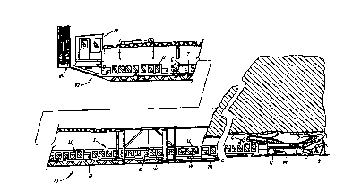
Figure 1 is a schematical view showing the
mining system in which the launch vehicle of the
present invention is integrated;
Figure 2a is a partially sectional schematic
view showing a modular u.lveyo~ unit resting on the
20 frame of the launch vehicle;
Figure 2b is a partially broken away,
detailed side elevational view of the pusher arm unit
adapted to operatively connect one of the reciprocating
drive cylinders to an individual conveyor unit;
Figure 2c is a detailed side elevational,
schematical view of the pusher arm unit showing the
pusher arm pivoted down and passing under a pin on a
Cullv~:yur unit;
Figures 3a and 3b are schematical side
30 elevational views adapted to illustrate the advancing
of the ~u~veyol train by the shuttling action of the
pair of cooperating tandem drive cylinder sets as well
as the addition of a modular conveyor unit to the
WO 92/10644 ~ 0 7 5 6 3 8 PCr/US91/0923~
~ ~ 14
train;
Figure 4a is a top plan view of the
ext~nc;hle front of the launch vehicle;
Figure 4b is a detailed front end view of the
5 extensible front shown in Figure 4a;
Figure 5 is a schematical representation
showing the r--h~n;- "~ adapted for positioning a
vt:~u~ unit on the launch vehicle; and
Figure 6 is a partially perspective
10 schematical view showing a front end loader preparing
to lift a modular ~ul-v~yul unit from the ground.
Reference will now be made in detail to the
present preferred ~Tnh9~1;r 1 of the invention, an
example of which is illustrated in the A'~_ -nying
15 drawing.
Det~; l ed Des~rintiQn of the Invention
Reference is now made to Figures 2a, 3a and
3b schematically showing the launch vehicle 10 of the
present invention. As indicated above with reference
20 to Figure 1, the launch vehicle 10 is adapted for
utilization with a continuous mining system including a
continuous mining machine M of a type known in ~he art.
The mining machine M includes a rotating cutter head
drum D supporting a series of cutting bits on helical
25 flights (not shown). The cutter head drum D is
rotatably mounted on a vertically moveable boom that is
pivotally mounted on the main frame member of the
mining machine M. As also shown, the mining machine is
supported for ~ "e,-t along the floor of the mine by a
30 pair of crawler assembLies N.
In operation, the mining machine M is
preferably advanced into the seam face S with the boom
raised and the cutter head drum D rotating. As the
2~75638
cuttlng beglns at the top level or roof llne of the seam, the
mlnlng machlne M 18 advanced ~urther forward and the boom 18
gradually lowered. As the minlng machlne M is advanced and
the boom 18 ralsed and lowered, coal C 18 cut from the seam
face S. The aggregate coal C 18 then collected by means o~ a
conventlonal gathering head that serves to dellver the
aggregate coal to a fllght conveyor F.
As shown ln Flgure l, the f llght conveyor F dellvers
the aggregate coal C to the lead conveyor unlt o~ a conveyor
traln generally deslgnated by reference letter T. The
conveyor traln also lncludes a serles o~ modular conveyor
unlts U ldentlcal to one another that are releasably coupled
together ln serles behlnd the lead conveyor unit.
As best descrlbed ln Unlted States 5,112,111 each of
the conveyor unlts U includes a maln structural frame
supported for r- v~ t. on the ground by a serles of wheels W.
Each conveyor unit U also lncludes a centrally dlsposed,
longltudlnally extendlng lncllned conveyor. The conveyor,
whlch 18 preferably of the belt type, operates to convey
aggregate coal C recelved at the low end to the hlgh end where
lt 18 dlscharged from one conveyor unlt to the next conveyor
unit in the serles. ~ach conveyor unlt also lncludes its own
motor for drlvlng the belt conveyor held thereln. The unlts U
of the conveyor train T are also lnterconnected by means of
control llnes that are flrst routed from a power source such
as a generator (not shown) on the bench to
74320-4
WO 92/10644 2 ~ 7 5 ~ 3 8 PCr/US91~0923~
16
the mining machine r~ and back through the individual
co"~/eyul units U. Accordingly, the motors of the
~u~.veyoL units are connected in series for simultaneous
operation at a substantially consistent speed.
Each of the CO~IV~yuL units ~U also includes a
coupling - -hAni F'n G specifically adapted to allow the
units to be coupled together in a rigid manner so that
the units of the train T remain in completely straight
alignment behind the mining machine ~1. Such a coupling
10 r-ch~ni c~ may, for example, include cooperating
clevises on each conveyor unit that are received
together in an interdigitating manner and connected by
means of a pin.
As should be appreciated from viewing Figure
15 1, the Cc,-vt:yuL train T in~ F~ as many CullvtyuI units
U as are nec~F~sAry to have the train extend out of the
seam to the launch vehicle 10 on the bench B. As
shown, preferably the bench is undercut below the
bottom of the seam so as to receive the launch vehicle
20 or platform 10.
As best shown in Figures 2a, 3a and 3b, the
launch vehicle 10 includes a main structural r. JL}.
12 that supports an aggregate material conveyor 14,
preferably of the belt type. This conveyor 14 receives
25 the aggregate coal C from the last l,~llVeyUL unit U of
the train T. The coal C is then delivered by the
a~yL~te material CO~lV~yOL 14 up an incline 16,
beneath the operator control cab 18, to a discharge
conveyor 20. The discharge conveyor 20 is also
30 inclined and may, for example, be utilized to convey
the aggregate coal C to a delivery location such as the
bed of a truck which is used to haul the coal away for
stockpiling or further processing.
As also shown in Figures 2a, 3a, and 3b, the
,~ ~
WO 92/l0~ 7 ~ ~ 3 8 PCIIUS91109234
17
launch vehicle 10 includes a safety canopy 22. The
safety canopy 22 is connected to the main structural
Lr '~Lk 12 by a series of spaced support posts 24 and
braces 26. Two series of jacks 28 are provided spaced
5 along the length of the launch vehicle 10~ The jacks
28 are supported on skids 30 and may be actuated to
lift the main framework 12 of the launch vehicle 10
from the bench B so as to allow ~ v ~ of the launch
vehicle by heavy equipment or by auger skids to a
10 mining location as described in greater detail below.
As also shown in Figure 2a, the launch
vehicle 10 includes a pair of spaced guide tracks 31 in
the form of spaced floor grate sections that are
adapted to support the ground engaging wheels W of the
15 modular conveyor units U. Additionally, a pair of
guide rails 32 are provided adjacent and outside the
sides of the aggregate conveyor 14. These guide rails
32 extend upwardly above the floor grate sections 31
and outwardly from the aggregate material Cullvt:yur 14
20 toward the inner surfaces of the ground engaging wheels
W of the conveyor units U. In the event a CU1IV~YUL
unit U is positioned on the launch vehicle 10 slightly
out of alignment with the aggregate material CUIIV~YUL
14, the inner surfaces of the wheels will engage the
25 rails 32 thereby realigning the modular L:ullv~yùl unit U
with the conveyor train T as n~c~Cc;~ry to insure proper
alignment. Advantageously, by maintaining proper
alignment of the end unit of the Cu.,vtyuL train T so
that it overlies the launch vehicle conveyor 14,
30 aggregate material from the ~_OIIV~UL train is received
and conveyed by the launch vehicle conveyor at all
times of operation.
As best shown in Figures 3a and 3b, the
launch vehicle 10 also includes a drive assembly,
WO 92/10644 2 0 ~ ~ 6 3 8 PCI/US91/0923~
18
generally designated; b~y reference numeral 34. The
drive as6embly 34 is specifically adapted for
selectively aiding in the advAnc~ ~ or withdrawal of
the conveyor train T. More specifically, the drive
5 assembly 34 includes a pair of cooperating tandem drive
cylinder sets 36, 38. Only one drive cylinder of each
set 36, 38 is shown in Figures 3a and 3b as the tandem
cylinders of each set are mounted to the main framework
12 on opposing sides of the launch vehicle conveyor 14
10 (see also Figure 2a). As shown, the forward tandem
drive cylinder set 36 is mounted longi~ nAl ly aligned
with and spaced from the rearward drive cylinder set
38. Further, as also made clear from viewing Figure
2a, each tandem cylinder set 36, 38 has a left side and
15 right side cylinder. Both of the tandem cylinders of
the forward set 36 operate together. Similarly, both
of the tandem cylinders of the rearward set 38 operate
together .
- Each drive cylinder of sets 36, 38 includes
20 an extensible cylinder rod; 40. A pusher arm unit 42 is
mounted to a distal end of each cylinder rod 40. As
best shown in Figures 2b and 2c, each pusher arm unit
42 includes a substantially V-shaped pusher arm 44
pivotally mounted to a base 46 by means of a pivot pin
25 48. As described in greater detail below, the pusher
arm 44 may be selectively positioned in a first
position (shown in full line in Figure 2b) for engaging
a cooperating pin P on a conveyor unit U and advancing
the collv~yul train T into the coal seam S.
30 Alternatively, the pusher arm 44 may be selectively
positioned in a second, opposite position (shown in
phantom line in Figure 2b) for also engaging a
cooperating pin P and withdrawing the conveyor train T
from the coal seam S.
~ .
WO 92/l0644 ~! O i ~ 6 3 g PCl/USg~109234
19
Advantageously, the drive assembly 34 is
sufficiently powerful to aid in advancing (withdrawing)
the conveyor train T and mining machine M into (from~
the seam face F. This is a particularly important
5 advantage to the present system as in many mining areas
soft bottom conditions, such as fire clay, exist. The
crawler assemblies N on a conventional mining machine M
tend to dig ruts in the soft bottom until the main
frame of the mining machine "high centers" and comes to
10 rest on the undisturbed bottom material between the
ruts. Accordingly, continuous mining machines M have a
propensity to become stuck where soft bottom conditions
are present. As such, mining of these types of seams
was often avoided in the past. In contrast, with the
15 present system, mining of these seams is now possible.
Thus, the present apparatus effectively opens new areas
for mining thereby increasing recoverable coal
reserves .
In order to insure that the launch vehicle 10
20 remains stationary as the drive assembly 34 is operated
to aid in the adv~n~ ~ or withdrawal of the conveyor
train T and continuous miner N, the launch vehicle may
be anchored to the bench B. This may be achieved in
any manner known in the art. one approach is to drill
25 a series of holes down into the bench B. Steel pipes
up to six inches in diameter may then be ~Yt~n~d down
into the holes and a taut steel cable may then be
attached between each pipe and the launch vehicle 10.
Together, the cables and pipes serve to effectively
30 hold the launch vehicle 10 in position during operation
of the drive assembly 34.
The launch vehicle 10 of the present
invention also includes a ~ ^h~niFm for adding
individual modular conveyor units U to the conveyor
WO 92/l0644 ~2 0 7 5 ~ 3 8 PCr/US91/092
train T as it is advanced into the coal seam. The
n;~r for adding a modular conveyor unit is
generally designated by referance numeral 52 and best
shown in Figures 3a, 3b and 5. A5 best shown
5 schematically in Figure 5, the conveyor unit adding
r~^hAni C~n 52 includes a power source or drive motor 54
connected via a power output transmission (not shown)
to a pair of take-up reels 56. Each take-up reel 56 is
rotatably mounted upon a shaft 58 held in a cradle 59
10 mounted to the overlying canopy 22. One take-up reel
56 is mounted adjacent the operator cab 18. The other
t2ke-up reel 56 is mounted forward of the first one
approximately the length of a Cullv~yùL unit (e.g. 45
feet) .
A line or heavy duty cable 60 is moun~ed to
each take-up reel 56. More particularly, the proximal
end of each line 60 is attached to the associated take-
up reel 56 so that rotation of the reel pays out or
takes-up the line. The distal end of each line 60 is
20 attached by means of a yoke 62 to a sling 64 that holds
a cross bar 66. A pair of downwardly extending hooks
68 are attached to the cross bar 66 at each end. The
hooks 68 are adapted to engage the pins P at the ends
of a CCIIIV~YOL unit U to be SllcpPn~ by the winch lines
25 60. Of course, any other a~,ulu~Liate arrangement could
be utilized that is adapted for connecting the winch
lines 60 to a conveyor unit U.
Additionally, the launch vehicle 10 may be
equipped with an extensible front end generally
30 designated by reference numeral 72 and shown in
Figures 1, 4a and 4b. Advantageously, the
extensible front end 72 allows the launch vehicle 10 to
be positioned for operation even on relatively narrow
benches B. Additiûnally, when fully retracted, it
~ WO 92/10644 2 0 7 5 li ~ 8 PCr/USgl/09234
21
should be appreciated that the launch vehicle 10 is
significantly shorter in length thereby making it
easier to transport the launch vehicle from one mine
location to another. Further, the reduced length makes
5 it easier to move the launch vehicle 10 along the bench
B by means of heavy equipment such as a bulldozer from
one mining position to the next.
As best shown in Figure 4a, the extensible
front end 72 includes an extensible framework 74 having
10 a series of track members 76 adapted to support the
mining machine M or UullV~yuL units U of the conveyor
train T. The track members 76 are each received in
sliding, interdigitating engagement with a second
series of cooperatiDg track members 78 held stationary
15 on the mainframe 12. A pair of actuator cylinders 80
are connected to the extensible LL UL~ 74 by means
of yokes 82. These actuator cylinders 80 are adapted
to displace the extensible framework 74 between two
operative positions.
In the first operative position, the
extensible LL ..JLk 74 is retracted so that the first
6eries of track members 76 are received between the
second series of track members 78 on the mainframe 12.
Thus, the overall length of the launch vehicle is
25 shortened. In the second operative position, shown in
full line in Figure 4a, the extensible framework 74 is
extended so that the first series of track members 76
extend outwardly from the second series 78. The
extended track members 78 serve as a stable base or
30 floor to support the conveyor units U of the CU~IV~YUL
train .
As shown in Figure 11 it is even possible to
ex~end the extensible framework 74 and track members 76
beneath the highwall face. This is an area of the mine
WO 92/10644 ~ ) 7 5 6 3 8 PCI/US91/0923~
.
. --
22
floor where water often collects significantly
softening the floor conditions. Over time, such
softened conditions could lead to conveyor units U
settling down and bonr-; nq mired in the bottom
5 material. This is a particularly troublesome problem
where fire clay conditions exist. Advantageously, by
incorporating the extensible front end and utilizing it
as a support structure for the cul.ve~uL units in the
area adjacent the highwall face, this problem is
10 significantly reduced and in most instances avoided.
Operation of the preferred ` ~ L of the
present invention will now be described in detail.
Following the completion of surface mining, the bench B
is prepared with a b~ lnzor andJor other heavy
15 oSr'; L by undercutting below the bottom of the seam
floor a sufficient distance for the proper positioning
of the launch vehicle 10, if possible. The launch
vehicle 10 is then transported to the mining site and
positioned on the bench B. During transport, the
20 extensible front end 72 is fully retracted so as to
reduce the length of the launch vehicle as much as
possible for ease in hAn-ll ;nq.
Next, the launch vehicle 10 is moved directly
into position for mining by means of heavy oqn; -nt
25 such as a bulldozer. During this operation, the launch
vehicle 10 is raised on the jacks 28 50 as to be
resting on the skids 30 with the LL J~}. 12 raised
f rom contact with the bench B .
Once the launch vehicle 10 is properly
30 positioned for mining, the jacks 28 are retracted until
the main structural framework 12 rests securely on the
bench B. If desired, the extensible framework 74 may
then be extended so that the first series of tracks 76
extend, for example, underneath the highwall as shown
WO 92/l0644 2 ~ 7 ~ ~ 3 ~ PCr/US91/09234
23
in Figure l. There, the tracks 76 provide a firm,
stable base or floor to support the mining machine M
and cv--v~yc,~ units U of the train T as they advance
underground into the seam.
- In order to insure that the launch vehicle 10
- remains stationary as the drive assembly 34 is operated
to aid in the advance of the conveyor train T and
continuous miner M, the launch vehicle may also be
anchored to the bench B. This may be achieved in any
lO manner known in the art. One approach is to drill a
series of holes down into the bench. Steel pipes Inot
shown) may then be extended down into the holes and a
taut steel cable (not shown) is then attached between
each pipe and the launch vehicle 10. Together, the
15 cables and pipes serve to effectively hold the launch
vehicle in position during operation of the drive
assembly 34.
The mining machine M and the lead conveyor
unit U of the ~vllvr_yvl train are preferably positioned
2 0 on the launch vehicle 10 prior to moving the launch
vehicle into position on the bench B. With the crawler
asse_blies N of the mining machine M aligned with and
resting in the guide tracks 31, the boom of the mining
machine is raised to align the cutter head drum D with
25 the top of the seam. The cutter head drum D, gathering
head and flight C~JIIVt~Y-JL F of the mining machine M are
all then activated. Next, the crawler ~cs~mhl iec N are
engaged to advance the mining machine M toward the face
and into the seam. The mining machine M is operated in
30 a manner known in the art from the operator cab 18 to
win aggregate coal C from the seam face S. As the
mining machine M is being advanced into the seam the
lead conveyor unit U follows along in the guide tracks
31.
WO 92/10644 ~ Q 7 ~ ~ 3 8 PCI/US9~/0923
24
As the mining machine ~ advances a front end
loader L may be utilized to lift a modular conveyor
unit U and hold i'c for connection to the hooks 68 of
the conveyor lift - --h~ni cr 52 as shown in Figures 3a
5 and 5 . As shown in Figures 5 and 6 ! the conveyor unit
U is held by the front end loader L~;~in a position with
the ends of the unit directly unaer the cross bars 66.
The hooks 68 are then attached to the four pins P
adj acent the corners of the conveyor unit U . The winch
10 lines 60 are then taken-up slightly to remove all
61ack. The front end loader L is then disengaged from
the new c.-.ve~,r unit U (note action arrow Q) that is
now suspended by the winch line6 60, As the mining
machine M advances, the control lines of the new
15 modular Col,V~y-,L unit U held on the winch lines 60 are
connected to the control line6 of the last conveyor
unit of the conveyor train T ~in this instance, the
lead ~ u~v~yO~ unit) . This initiates operation of the
belt conveyor on the new ~llvc:yCl unit U. Again,
20 throughout this operation it should be realized that
the mining of coal is continuously taking place.
Once the mining ~achine ~ is sufficiently
advanced into the seam to provide clearance on the
launch vehicle 1~, the drive motor 54 is actuated so as
25 to evenly pay-out the winch lines 60 and lower the new
c~,.,veyu~ unit U until the ground engaging wheels W rest
upon the guide tracks 31 (note action arrow H in Figure
5). It should be appreciated that the wheels W
straddle the launch vehicle conveyor 14 (see Figures 2a
30 and 5). Next, the hook6 68 are manually disengaged
from the pins P and the winch lines 60 are taken-up to
the original raised position for subsequent receipt of
the next conveyor unit U.
A pusher cyl inder 8 8, mounted to the
~ WO 92/l0644 2 0 7 ~ ~ 3 ~ Pcr~usglJl)9~
framework 12 of the launch vehicle 10 beneath the
operator cab 18 is then activated to push (note action
arrow X in Figure 3b) the new conveyor unit U into
engagement with the rear of the conveyor train T
5 (again, in this instance into engagement with the lead
~ UllYt:yOL unit directly behind the mining machine) . As
shown, the pusher cylinder 88 includes an extensible
rod 89 having a bumper 90 at the distal end that
engages the rear of the new conveyor unit U. This
10 serves to drive the new conveyor unit U into engagement
with the rear of the CullV~yOI train T where it may be
coupled thereto in a manner described above. Once the
new conveyor unit U is coupled to the end of the
CUIIV~:YUL train T, the pusher cylinder 88 is recycled to
15 the fully retracted position shown in Figure 3a.
It should also be appreciated that throughout
the operation of adding a conveyor unit U to the
conveyor train T, aggregate coal is being cut and
~_ullveye~ cont;n~lo~lcly for recovery.
Nore particularly, as the first conveyor unit
U is being positioned on the launch vehicle 10,
ayyLc:yclte coal cut from the seam S by the mining
machine N is being passed by the flight conveyor F to
the lead COnVt!yùL unit of the conveyor train T. From
25 there the coal is delivered to each Eu~re~ i n~ unit U
of the CcllveyuL train T until it is discharged by the
end conveyor unit of the train onto the receiving
~ :yoL 14 of the launch vehicle 10. The receiving
conveyor 14 then conveys the aggregate coal under the
30 new conveyor unit U, that is to be added to the train,
to the discharge conveyor 20. The discharge conveyor
20 conveys the coal C to a delivery location, such as
the bed of a coal truck (not shown) for haulage to a
stock pile or for further processing.
WO 92/l0644 2 0 7 ~ ~ 3 8 PCr/US91/0923~
26
As the new conveyor unit U is positioned by
the lift r- ' ~n;~m 52 onto the guide tracks 31 and
advanced by the pusher cylinder 88 toward the rear of
the cu--veyoL train T, the receiving end of the new
5 conveyor unit begins to intercept the coal C being
discharged by the conveyor of the end unit of the
~UIIV~y~L train. As previously described, the conveyor
of the new unit is already operating when this occurs.
Accordingly, at interception the coal C is cullveyed
10 along the ~ullVeyuL of the new conveyor unit to the
discharge end where it is still delivered to the
receiving ~UIlV~yoL 14 of the launch vehicle 10. From
there the aggregate coal is cullveyed to the delivery
location as described above.
Once the new CO~Iveyul unit U is rigidly
coupled to the rear ~_ullVeyOL unit of the train T the
reciprocating drive assembly 34 may be operated to aid
in advancing the mining machine M and ~ullveyu~ train T
into the coal seam 5.
More particularly, as best shown in Figure
3b, when the pushing cylinder 88 is fully extended to
connect the ~;ullveyuI unit U the lead pins P at each
side of the cullveyu~ unit U are in position to be
engaged by the pusher arms 44 of the fully retracted
25 rearward tandem drive cylinders 38. The rods 40 of the
cylinders 38 are then extended synchronously and in
tandem to aid in adYancing the cG,.veyol train T and
mining machine M into the seam face S. The pushing
force is applied through the arms 44 that are
30 positioned to have an upright, leading section 47 for
engaging a rearwardly facing portion of a pin P and a
horizontally extending trailing section 49 that engages
the base 46 to hold the upright section 47 firmly in
pûsition .
WO 92/10644 ~ PCr~US91Jo9234
27
As the rearward drive cylinders 38 are
extended, the forward tandem cylinders 36 are recycled
from the fully extended position to the fully retracted
position. Thus, while the rearward tandem cylinders 38
5 aid in advancing the cul.v~yul train T and mining
machine M by operation in the direction of action arrow
Y, the forward tandem cylinders 36 are moving in the
reverse direction and recycled as indicated by action
arrow V.
It should be appreciated that the pusher arms
44 of the forward tandem cylinders 36 pivot down under
the pins P on the sides of the ~ullv~yol units U as they
move in the direction of action arrow V so as to allow
passage. More specifically, as best shown in Figure
lS 2c, each pusher arm 44 is mounted on a pivot pin 48 in
base 46. Accordingly, when the rear face engages a pin
P, the pusher arm 44 is cammed downwardly and pivots as
shown by the action arrow J to allow passage of the arm
under the pin. After passing under the pin P, the arms
20 44 of the forward tandem cylinders 36 are manually
returned to the upright, pin engaging and pushing
position shown in Figure 2b. This may be done, for
example, by pushing downwardly on the trailing section
49 and pivoting the arms 44 about the pivot pin 48.
As the rearward tandem cylinders 38 approach
their ~ ~ limit (see Figure 3a), the already fully
retracted forward tandem cylinders 36 are activated to
begin oYtPn~lin7 the cylinder rods 40 in the direction
of action arrow Z. As this is done, the arms 44 of the
30 forward tandem cylinders 36 engage the int~ te
pins P on the next-to-last conveyor unit U of the
conveyor train T. Continued extension of the forward
tandem drive cylinders 36 serves to continue to aid in
the advance of the mining machine M and conveyor train
.
WO 92/l0644 2 0 7 513 3 8 PCr/US91/D9~
'28
T. As the forward tandem cylinders 36 are extended in
the direction o~ action arrow Z and aid in the advance,
the rearward tandem cylinders 38 are recycled and move
in the opposite direction as shown by action arrow R.
5 A6 already described above, when the arms 44 of the
rearward tandem cylinder5 38 come into engagement with
a pin P, they are pivoted downwardly to allow passage
under the pin. After passing under two pins P, the
arms 44 of the rearward tandem cylinders 38 are
10 manually returned to the upright, pin engaging and
pushing position shown in Figure 2b in the above-
described manner.
As the forward tandem cylinder set 36
approaches its limit of r ~ ~, the already fully
15 recycled rearward tandem cylinders 38 begin to extend
the cylinder rods 40 until the arms 44 of the rearward
cylinders 38 engage the next set of pins P at the rear
of the ~u~veyus unit U. The shuttling operation of the
two tandem sets of cylinders 36, 38 then continues in
2 0 the manner described f or as many conveyor units U as
are added to the ullve:~u ~ train during the advance into
the coal seam. Of course, as should be appreciated,
the pusher arms 44 o~ each tandem cylinder set 36, 38
engage every other pin on the side o~ the conveyor
25 units U. Further, the pins P must be properly
positioned on the Co~lVeyOs units U so as to have equal
spacing between each pin cosLe~onding to the sparin~c
between and movement range of the tandem cylinder sets
36, 38. Additionally, it should be noted that
3 0 throughout the operation of advancing the mining
machine M and conveyor train T, coal is being u~.,ve~ed
without interruption.
once the maximum desired mining depth is
reached, the conveyor train T and mining machine M may
~ WO 92/I0644 2 0 7 ~ ~ 3 ~ PCI`IUS9~109234
29
be ~acked from the seam. This process is done a
conveyor unit U at a time.
More particularly, the arms 44 of the pusher
arm units 42 are disengaged from the cooperating pins P
5 of the CoIIvt:yu~ units U resting on the launch vehicle
10. The arms 44 are then pivoted over to the phantom
line position shown in Figure 2b (note action arrow K)
50 that the trailing sections 49 extend vertically and
the leading sections 47 extend horizontally. Next the
10 tandem drive cylinders 36, 38 are manipulated so as to
} ring one drive set of arms 44 into engagement with the
sides of the pins P nearest the coal seam face S. The
other set of arms 44 is driven to a fully recycled
position. The drive assembly 34 is then utilized in
15 conjunction with the crawler assemblies N of the mining
machine M to back the Cu--v~:yC~r train T and mining
machine N from the seam.
More specifically, when the forward tandem
cylinder set 36 is fully extended and engaging pins P
20 at each side of a Cullvt:yur unit U, the cylinder rods 40
are retracted. This action serves to aid the mining
machine in moving the coIlv~yur train away from the seam
face and back toward the operator cab 18. Of course,
in accordance with the shuttling operation of the
25 tandem cylinder sets, 36, 38, as the forward cylinder
set 36 is being retracted, the rearward cylinder set 38
is being extended. During extension of the rearward
cylinder set 38, the arms 44 are cammed under any pins
P with which they come into contact without adversely
30 effecting --~. t of the CoIlv~yu, train.
As the forward l ullv~yur set 36 approaches its
limit of - v. t. by ~e~ ; ng fully retracted, the
rearward cylinder set 38 begins retracting.
Accordingly, the arms 44 of the rearward cylinder set
WO 92t10644 2 0 ~ 5 ~ 3 ~ PCr/US91/0923~
38 are positioned to ,engage pins P on a conveyor unit U
80 as to provide assistance in withdrawing the conveyor
train T and mining machine M from the coal seam.
Hence, the trailing sections 49 are positioned to
5 extend vertically with the leading sections 47 engaging
- the base 46. As this is done, the forward cylinders 36
are re-extended (recycled~, once again, with the arms
44 of the forward units pivoting down beneath and
passing under any pins P that they engage during the
10 process. The arms 44 are then manually reset as
~lready described to engage the pins P as reguired.
This shuttling operation of the cylinder sets 36, 38
continues until a Cu.,vt yuL unit U reaches the rearmost
end of the launch vehicle 10. At that point in time,
15 the rearmost Cc..vt:yuL unit U is disconnected from the
~ ol.v~:yul train T and a front end loader L is utilized
to remove that ~ conn~cted cu"vey~L unit from the
launch vehicle 10.
The process of removing the ~ ullV~yUL units U
20 of the ~_u~ve~yur train T continues in this manner until
the lead c;u~,vey~r unit and mining machine M are
positioned once again on the guide tracks 31 of the
launch vehicle 10. At that point in time the launch
vehicle 10 is released from the anchoring system (e.g.,
25 anchoring cables may be rli~connected from the launch
vehicle and the anchoring pipes may be removed from the
bench). The launch vehicle frame 12 is then raised
from the bench B by means of the j acks 28 . Heavy
eguipment such as a bulldozer is then utilized to push
30 the launch vehicle 10 on the skids 30 to the next
mining location. Alternatively, the launch vehicle 10
is eSIuipped with auger skids for this purpose. If
desired to aid in the movement of the launch vehicle
10, the extensible front end 72 may first be fully
~ WO 92/10644 2 Q 7 5 6 3 8 Pcr~usglJo9~
31
retracted. More specifically, the cylinders 80 are
actuated so as to retract the extensible framework 74
until it is fully received within the main framework 12
of the launch vehicle 10.
Once positioned to continue mining, the
launch vehicle framework 12 is again lowered by the
jacks 28 until it engages with the bench B. The
anchoring system is then reset, the extensible
framework 74 is re-extended if desired, and mining
10 operations proceed in the manner described above.
In summary, numerous benefits result from
employing the concepts of the present invention. The
launch vehicle 10 may be utilized in a system to
provide continuous, uninterrupted cutting and conveying
15 of coal from a seam face so as to ~-~;mi ~e production.
Advantageously, the cutting and conveying of the
aggregate material continues even as additional modular
conveyor units U are being added to the conveyor train
T. Further, the launch vehicle 10 includes a drive
20 assembly 34 that aids in selectively advancing or
withdrawing the mining machine and the COIlVeyuL train
into or from the coal seam. This is a major advantage
in areas with soft bottom material such as fire clay.
In fact, the launch vehicle 10 allows efficient mining
25 of such areas which was not truly possible in the past.
Further, since this is achieved without tearing up the
mine floor, recovered product is not contaminated with
bottom material.
The foregoing description of a preferred
30 embodiment of the invention has been presented for
purposes of illustration and description. It is not
intended to be exhaustive or to limit the invention to
the precise form disclosed. Obvious modifications or
variations arê pOssiblê in light Of thê above
WO 92/10644 PCr/US91/0923~_
r7 ~ 6` 3 8 -- ~
32
teachings. For example, the positioning unit 52 may be
a hydraulic cylinder set rather than the winch system
described. The ` ' i - Ls were chosen and described
to provide the best illustration of the principles of
5 the invention and its practical application to thereby
enable one of ordinary skill in the art to utilize the
invention in various r~`~orlir~nts and with various
modifications as are suited to the particular use
contemplated. All such modifications and variations
10 are within the scope of the invention as detPrminP-l by
the appended claims when interpreted in accordance with
the breadth to which they are fairly, legally and
eq~lit~b y ~ le~.
.