Sélection de la langue

Search

Sommaire du brevet 2075777 

Énoncé de désistement de responsabilité concernant l'information provenant de tiers

Une partie des informations de ce site Web a été fournie par des sources externes. Le gouvernement du Canada n'assume aucune responsabilité concernant la précision, l'actualité ou la fiabilité des informations fournies par les sources externes. Les utilisateurs qui désirent employer cette information devraient consulter directement la source des informations. Le contenu fourni par les sources externes n'est pas assujetti aux exigences sur les langues officielles, la protection des renseignements personnels et l'accessibilité.

Disponibilité de l'Abrégé et des Revendications

L'apparition de différences dans le texte et l'image des Revendications et de l'Abrégé dépend du moment auquel le document est publié. Les textes des Revendications et de l'Abrégé sont affichés :

  • lorsque la demande peut être examinée par le public;
  • lorsque le brevet est émis (délivrance).
(12) Demande de brevet: (11) CA 2075777
(54) Titre français: DISPOSITIF POLYVALENT POUR L'IMMOBILISATION D'UN CONTENEUR FIXE AU PLANCHER D'UN WAGON DE MARCHANDISES
(54) Titre anglais: ALL PURPOSE SPINE CAR CONTAINER FLOOR RESTRAINT
Statut: Réputée abandonnée et au-delà du délai pour le rétablissement - en attente de la réponse à l’avis de communication rejetée
Données bibliographiques
(51) Classification internationale des brevets (CIB):
  • B61D 45/00 (2006.01)
  • B60P 07/10 (2006.01)
  • B61D 03/18 (2006.01)
  • B61D 03/20 (2006.01)
(72) Inventeurs :
  • HESCH, HAROLD E. (Etats-Unis d'Amérique)
(73) Titulaires :
  • TRINITY INDUSTRIES, INC.
(71) Demandeurs :
  • TRINITY INDUSTRIES, INC. (Etats-Unis d'Amérique)
(74) Agent: KIRBY EADES GALE BAKER
(74) Co-agent:
(45) Délivré:
(22) Date de dépôt: 1992-08-11
(41) Mise à la disponibilité du public: 1993-02-13
Licence disponible: S.O.
Cédé au domaine public: S.O.
(25) Langue des documents déposés: Anglais

Traité de coopération en matière de brevets (PCT): Non

(30) Données de priorité de la demande:
Numéro de la demande Pays / territoire Date
744,467 (Etats-Unis d'Amérique) 1991-08-12

Abrégés

Abrégé anglais


17
ALL PURPOSE SPINE CAR
CONTAINER FLOOR RESTRAINT
ABSTRACT OF THE INVENTION
A container floor restraint for a freight rail car
is provided. The car has a longitudinally extending
center sill and a plurality of cross beams extending
transversely thereof. The car further has a load
supporting assembly at one end and a load supporting deck
at the other. The container floor restraint includes a
first pair of arms extending generally outwardly and
perpendicularly from the center sill at a predetermined
distance from the load supporting assembly, each arm
being substantially opposed to one another. A second
pair of arms extend generally outwardly and
perpendicularly from the center sill spaced apart from
the first pair of arms. The arms have outer ends
extending substantially equidistantly from the center
sill and are attached to first and second brace members.
The brace members extend longitudinally alongside and
generally parallel to the center sill. Additionally,
channel braces are disposed longitudinally on the center
sill spread from the first pair of arms and provide
further restraint to a container floor.

Revendications

Note : Les revendications sont présentées dans la langue officielle dans laquelle elles ont été soumises.


11
WHAT IS CLAIMED IS:
1. A freight rail car having first and second
ends, a longitudinally extending center sill between said
first and second ends, and at least one structural member
extending transversely of said center sill, said center
sill having a top surface generally lying in a horizontal
plane, said first end having a load supporting assembly
including a foldable wheel assembly, said second end
having a load supporting deck, the car comprising:
a first pair of arms each extending generally
horizontally outwardly from said center sill at a
predetermined distance from said load supporting
assembly, said arms being substantially opposed to one
another;
a second pair of arms each extending generally
horizontally outwardly from said center sill, spaced from
said first pair of arms, said arms being substantially
opposed to one another, said first and second pairs of
arms being substantially below said horizontal plane
formed by said center sill top surface, and said arms
having outer ends extending substantially equidistantly
from said center sill;
first and second brace members each firmly attached
to said outer ends of said first and second pairs of said
arms, each said first and second brace member extending
longitudinally and being substantially parallel to said
center sill; and
means for elevating a selected top surface portion
of said center sill, said elevating means being disposed
between said foldable wheel assembly and said first pair
of arms.
2. The car, as set forth in claim 1, wherein said
elevating means comprises at least one longitudinally
extending member disposed on and firmly attached to said
top surface of said center sill.

12
3. The car, as set forth in claim 1, further
comprising first and second channel members each having a
predetermined length and mounted longitudinally on said
center sill at a second predetermined distance from said
load supporting assembly, said channel members being
substantially parallel and spaced from one another.
4. The car, as set forth in claim 1, wherein the
car further transports semitrailers having a landing
gear, said first and second pairs of arms being located
at said predetermined distance from said load supporting
assembly to provide clearance for said landing gear.
5. The car, as set forth in claim 1, wherein said
center sill includes two substantially vertical and
parallel side walls, said first pair of arms each being
substantially triangular in shape, one side of said
triangular shape forming a top surface of said arm and
another side joining said side wall of said center sill.
6. The car, as set forth in claim 1, wherein said
center sill includes two substantially vertical and
parallel side walls, said second pair of arms each being
substantially triangular in shape, one side of said arm
forming a top horizontal surface of said arm and another
side joining said side wall of said center sill.
7. The car, as set forth in claim 6, wherein the
car has a brake apparatus mounted to said side wall of
said center sill, one arm of said first pair of arms is
offset from said other opposing arm to provide clearance
for said brake apparatus.

13
8. A freight rail car having a first and second
ends and a longitudinally extending center sill, said
center sill having a top surface generally lying in a
horizontal plane, the car further having a hitch
supporting assembly at a predetermined distance from said
first end and a pair of platforms for receiving
semitrailer wheels located at each side of said center
sill a second predetermined distance from said second
end, the car comprising:
a first pair of arms each extending substantially
horizontally, outwardly from each side of said center
sill at a first predetermined distance from said hitch
supporting assembly, said first pair of arms
substantially opposing one another and having outer ends
extending substantially equidistantly from said center
sill;
a second pair of arms each extending horizontally
and outwardly from each side of said center sill spaced
apart from said first pair of arms and at a second
predetermined distance from said platforms, said second
pair of arms substantially opposing one another, said
first and second pair of arms having outer ends extending
equidistantly from said center sill; and
a center brace member mounted longitudinally on said
center sill between said hitch supporting assembly and
said first and second pairs of arms for elevating a
portion of the top surface of said center sill.

14
9. The car, as set forth in claim 8, wherein said
center sill has two substantially vertical and parallel
side walls, each arm of said first and second pairs of
arms further include:
a triangular crossbearer having three sides, one
side being attached to said side wall of said center
sill, another side forming a top surface of said arm and
at substantially the same elevation as top surface of
said center sill; and
a first and second reinforcing brace coupled to said
outer ends of said first and second pairs of arms
respectively and connecting said outer ends on each side
of said center sill, said first and second reinforcing
braces being substantially parallel with said center
sill.
10. The car, as set forth in claim 8, wherein said
center brace member includes a first and second channel
member having a predetermined length and mounted
longitudinally on said center sill at a third
predetermined distance from said hitch supporting
assembly, said channel members being substantially
parallel and spaced apart from one another.
11. The car, as set forth in claim 8, wherein the
car further transports semitrailers having a landing
gear, said first and second arms being located at said
first predetermined distance from said hitch supporting
assembly to provide clearance for said landing gear.
12. The car, as set forth in claim 8, wherein said
first pair of arms are slightly offset from one another.

13. A freight rail car comprising:
a center sill extending longitudinally between a
first and second ends of said car;
a plurality of spaced apart spine members extending
transversely of said center sill in a second half of said
car adjacent to said second end;
a foldable load supporting assembly mounted
substantially adjacent to said first end of the car;
two load supporting decks mounted on both sides of
said center sill adjacent to said second end of the car
for receiving semitrailer wheels;
an elongated channel member mounted longitudinally
on a top surface of said center sill for elevating the
elevation of said center sill top surface;
a first pair of arms each extending generally
horizontally outwardly and perpendicularly from said
center sill at a predetermined distance from said
foldable load supporting assembly and being in a first
half of the car adjacent said first end, each arm being
substantially opposed to one another but being slightly
offset from one another;
a second pair of arms each extending generally
horizontally outwardly and perpendicularly from said
center sill spaced apart from said first pair of arms,
each arm being substantially opposed to one another, said
first and second pairs of arms being substantially below
the elevation of said center sill top surface, and said
first and second pairs of arms having outer ends
extending substantially equidistantly from said center
sill; and
first and second brace members each firmly attached
to said outer ends of said first and second pairs of said
arms, each said first and second brace member extending
longitudinally and being substantially parallel to said
center sill.

16
14. The car, as set forth in claim 13, wherein the
car further transports semitrailers having a landing
gear, said first and second pairs of arms being located
at said predetermined distance from said foldable load
supporting assembly to provide clearance for said landing
gear.
15. The car, as set forth in claim 13, wherein said
center sill includes two substantially vertical and
parallel side walls, said first pair of arms each being
substantially triangular in shape, one side of said
triangular shape forming a top surface of said arm and
another side joining said side wall of said center sill.
16. The car, as set forth in claim 13, wherein said
center sill includes two substantially vertical and
parallel side walls, said second pair of arms each being
substantially triangular in shape, one side of said arm
forming a top horizontal surface of said arm and another
side joining said side wall of said center sill.
17. The car, as set forth in claim 13, wherein said
elongated channel member comprises a pair of beams having
U-shaped cross-sections.

Description

Note : Les descriptions sont présentées dans la langue officielle dans laquelle elles ont été soumises.

ALL PURPOSE SPINE CAR
CONTAINER FLOOR RESTRAINT
TECHNICAL FIELD OF THE INVENTION
This invention relates in general to the field of
railway cars. More particularly, the present invention
relates to an all purpose spine car container floor
restraint.

~ J~
BACKGROUND OF THE INVENTION
Railway spine cars have been used to carry freight
containers and semitrailers. Spine cars generally have a
platform formed by a center sill running longitudinally
down its center line with a series of parallel
crossbearers extending transversely of the sill. Because
the spine car does not have a solid floor, the American
Association of Railroads (AAR) requires restraints on
spine cars sufficient to brace a failed container floor.
One response to AAR's requirement was to provide a
set of parallel channels along the top of the center
sill. This solution is far less than ideal however,
because these channels interfere with semitrailer brake
- 15 equipment and underslung refrigeration equipment.
Another response to the AAR requirement was to provide
outriggers on the cars and limit the use of these cars to
container hauling only. Therefore, existing
modifications to spine cars to provide a container floor
restraint yielded structures that limit the application
and usefulness of the spine cars.
Accordingly, it is desirable to construct a spine
car with a structure that would provide a restraint to
failed container floors as required by the AAR. In
addition, when a semitrailer is mounted on the car, the
container floor restraint must provide adequate clearance
for trailer equipment. Because the weight of a railway
car is at a premium, the container floor restraint
structure must achieve its function while adding a
minimal amount of weight to the weight of the car.

~ ~ r I ~ D ~;J d 7
SUMMARY OF THE INVENTION
In accordance with the present invention, an all
purpose spine car container floor restraint is provided
which substantially eliminates or reduces disadvantages
and problems associated with prior railway cars.
In one aspect of the present invention, a container
floor restraint for a freight rail car is provided. The
car has a longitudinally extending center sill and a
plurality of cross beams extending transversely thereof.
The car further has a load supporting assembly at one end
and a load supporting deck at the other. The container
floor restraint includes a first pair of arms extending
generally outwardly and perpendicularly from the center
sill at a predetermined distance from the load supporting
assembly, each arm being substantially opposed to one
another. A second pair of arms extend generally
outwardly and perpendicularly from the center sill and
are spaced apart from the first pair of arms. The arms
have outer ends extending substantially equidistantly
from the center sill and are attached to first and second
brace members. The brace members extend longitudinally
alongside and generally parallel to the center sill.
In another aspect of the present invention, a
freight rail car is provided. The rail car comprises a
longitudinally extending center sill between a first and
second end of the car and a plurality of spaced apart
spine members extending transversely of the center sill
in a second half of the car adjacent to the second end.
A foldable load supporting assembly is mounted
substantially adjacent to the first end of the car as
well as two load supporting decks mounted on both sides
of the center sill adjacent to the second end of the car
for receiving semitrailer wheels. An elongated channel
member is mounted longitudinally on a top surface of the
center sill for elevating the elevation of the center

4 ~J~ ;J7
sill top surface. A first pair of arms which extend
generally horizontally outwardly and perpendicularly from
the center sill at a predetermined distance from the
foldable load supporting assembly is provided. A second
pair of arms extends generally horizontally outwardly and
perpendicularly from the center sill and are spaced apart
from the first pair of arms. The arms of the first and
second pairs are mounted to substantially oppose one
another. ~he free ends of the arms are attached to a
first and second brace member extending longitudinal~y
and substantially parallel to the center sill.
An important technical advantage of the present
invention provides a container floor restraint which
meets the requirements of the AAR. A further advantage
of the present invention provides a constructisn that
does not obstruct clearance required for semitrailer or
rail car equipment. Additionally, because the weight of
a railway car is at a premium, the container floor
restraint achieves its function while adding a minimal
amount of weight to the car.

~5fi J .~
BRIEF DESCRIPTION OF THE DRAWI~GS
For a better understanding of the present invention,
reference may be made to the accompanying drawings, in
which:
FIG. 1 is an elevational side view of an
intermediate spine car incorporating a preferred
embodiment of the container floor restraint of the
present inve~tion;
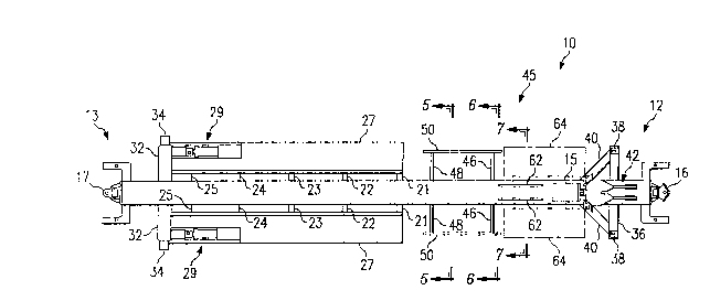
FIG. 2 is a top view of the intermediate spine.car;
FIG. 3 is an elevational side view of an end spine
car incorporating the preferred embodiment of the
container floor restraint of the present invention;
FIG. 4 is a top view of the end spine car;
FIG. 5 is a cross-sectional view taken substantially
along sectional lines 5-5 in FIGS. 2 and 4;
FIG. 6 is a cross-sectional view taken substantially
along sectional lines 6-6 in FIGS. 2 and 4; and
FIG. 7 is a cross-sectional view taken substantially
along sectional lines 7-7 in FIGS. 2 and 4.

6 ~1~jt~
DETAILED_DESCRIPTTON OF THE INVENTION
With reference to the drawings, FIGS. 1 and 2
illustrate an intermediate railway car unit 10 having
first and second ends 12 and 13 respectively and a
longitudinally extending center sill 15. The car unit 10
forms part of a five-unit car (not shown). Center sill
15 generally supports the load placed on the car, such as
a container or a semitrailer, and withstands towing
loads. Ends 12 and 13 of car unit 10 include couplers 16
and 17 for joining car unit 10 with other railway car
units in a train (not shown). Wheels 19 which form part
of a truck and swivel coupling that provide common
support for adjacent units in the car as is well known in
the art. The wheels 19 support car unit 10 at both ends
12 and 13. An elongated reinforcing beam 14 is further
coupled longitudinally to the substantially vertical side
walls of center sill 15 to strengthen the structure
thereof.
Conceptually, car unit 10 may be divided into two
halves, a first half from first end 12 to an imaginary
midpoint, and a second half from generally the mid point
to second end 13. In the second half of car unit 10, a
plurality of pairs of transverse cross beams 21-25 are
connected to the side walls of center sill 15 at
respective sites substantially equidistance from one
another. Two decks or platforms 27 are mounted on cross
beams 21-25 on both sides of center sill 15 for receiving
semitrailer wheels. Container locking assemblies 29 are
folded into platforms 27 when not in use, but project
through openings in platforms 27 when carrying a
container. opposing bolsters 32 are attached to the
center sill side walls and extend horizontally and
outwardly therefrom.
In generally the first half of car unit 10,
crossbearers 36 are attached to center sill side walls

2 f 3 . ~ ~ ~ ~
adjacent first end 12. Crossbearers 36 include container
locks 38 on their free ends and are braced by beams 40.
Beams 40 extend diagonally from the free ends of
crossbearers 36 to center sill 15 and connect therewith.
A foldable fifth wheel plate assembly or semitrailer
coupler 42 is accommodated in a recess or depression
formed by crossbearers 36, beams 40 and center sill 15.
Coupler 42 is raised into an operative position when car
unit 10 i5 carrying a semitrailer. Car unit 10 described
above and shown in FIGS. 1 and 2 is an intermediate car
to be connected between two end cars, which are described
below in conjunction with FIGS. 3 and 4. Related patent
application Serial No. 07/498,227, filed March 23, 1990,
and entitled "All Purpose Car" may be consulted for more
detailed description of car unit 10.
Intermediate car unit 10 further comprises a
container floor restraint, indicated generally at 45 and
constructed in accordance with the preferred embodiment
of the present invention. Container floor restraint 45
includes a first pair of outwardly extending arms or
beams 46. Arms 46 are attached to the side walls of
center sill 15 opposite each other and extending
substantially horizontally and perpendicularly therefrom.
A second pair of outwardly extending arms 48 are attached
to the center sill side walls spaced from the first pair
of arms 46. The free ends of each pair of arms 46 and 48
extend equidistantly outward from center sill 15. Braces
50 are mounted on the free ends of arms 46 and 48 on both
sides of center sill 15. The ends of braces 50 generally
extend longitudinally beyond the free ends of arms 46 and
48. Arms 46 and 48 and braces 50 in effect form two
rectangular retaining brackets, one on each side of
center sill 15.
Referring to FIG. 5, a cross-sectional view of arms
48 and braces 50 taken along lines 5-5 of FIGS. 2 and 4

;~ r, t ~.d ~ 7 ~
is shown. Arms 48 are generally triangular in shape with
one side attached to the center sill side walls 49 and
51. A n~tch is formed therein to accommodate and be
attached to reinforcing beam 14. A second side of arms
5 48 forms the top surface 52 thereof. Top surface 52 is
preferably at an elevation substantially below the top
surface 54 of center sill 15. A portion of a container
is shown to indicate its positioning and relative
elevation with respect to center sill 15 and arms 48.
10 Braces 50 are preferably U-shaped beams attached to arms
48 as shown.
Referring presently to FIG. 6, a cross-sectional
view showing center sill 15 and arms 46 taken along lines
6-6 of FIGS. 2 and 4 is shown. The second pair of arms
15 46 extends from the side walls 49 and 51 of center sill
15. The top surface 56 thereof lies generally below the
elevation of center sill top surface 54 but is generally
at the same elevation as that of arms 48. The outer free
ends of arms 46 are attached to braces 50. Arms 46 are
shown having orifices 58, but such features are not
imperative to the operations of the present invention. A
portion of the container load is also shown to indicate
its relative position with respect to arms 46.
Returning to FIGS. 1 and 2, positioned immediately
adjacent to the first pair of arms 46 are a pair of
channel braces 62 mounted on top of center sill 15. The
length of channel braces 62 is such that they do not
interfere with the operations of foldable fifth wheel
assembly 42 and any other equipment on the semitrailer
load. Areas 64 alongside center sill 15 and generally
bounded by arms 46, crossbearers 36 and beams 40 must
remain free of obstructions for clearance of semitrailer
landing gears (not shown).
Referring to FIG. 7, a cross-sectional view showing
center sill 15 and channel braces 62 is shown. Channel

~ . "7~ 7
braces 62 are each U-shaped with the open end mounted
toward the center line of center sill 15. Constructed in
this manner, channel braces 62 effectively raise the
elevation of a portion of the top surface of center sill
15 toward the floor of a container load. In the
preferred emkodiment, channel braces 62 add a three inch
height to center sill 15.
Referring to FIGS. 3 and 4, the application of
container floor restraint 45 to an end railway car unit
65 is shown. End car unit 65 has an end frame assembly
68 and a standard railway coupler (not shown) at a first
end 69 and a coupler assembly 70 at a second end 71. A
plurality of cross beams 73-77 span transversely a center
sill 80 in a second half of car unit 65 generally between
a center crossbearer 82 and second end 71. Center
crossbearer 82 is mounted ~xtending from center sill 80
at approximately the midpoint between ends 69 and 71 and
has container locks 84-87 disposed on its free ends.
Mounted and supported on top of cross beams 73-77 are
platform 89 and 90 for receiving semitrailer wheels.
Locking assemblies 92 are arranged and stowed away in
platform 89 and 90 when not in use, as shown. Near first
end 69 of car unit 65 and end frame assembly 68 is a
foldable wheel assembly 94.
Disposed between center crossbearer 82 and foldable
wheel assembly 94 is container floor restraint 45.
Container floor restraint 45 for an end car unit 65 is
substantially the same as that for an intermediate car
unit 10 as described above. It includes a first pair of
arms 96, a second pair of arms 98 extending outwardly
from center sill 80, and braces 100 attached to the free
ends of arms 96 and 98. A pair of channel braces 102 are
mounted on top of center sill 80 and disposed between
arms 96 and foldable fifth wheel assembly 94. Clearance
area 104 is further provided for the semitrailer landing

gear~ As shown, arms 96 and 98 are mounted on center
sill 80 as so not to interfere with the structure and
operations of an air brake reservoir 106 and an air brake
control valve 108. In order to accommodate control valve
108 and enable it to be replaced when necessary, the left
arm of a~ms 96 is required to be offset forward slightly
from the other arm. The offset is approximately seven
inches in the arrangement shown. Cross-sectional views
of arms 96, 98, braces 100, and channel braces 102 are
shown in FIGS. 5-7, which are identified by reference
numerals of FIGS. 1 and 2, but are equally applicable to
FIGS. 3 and 4.
Although the present invention has been described in
detail, it should be understood that various changes,
substitutions and alterations can be made thereto without
departing from the spirit and scope of the present
invention as defined by the appended claims.

Dessin représentatif
Une figure unique qui représente un dessin illustrant l'invention.
États administratifs

2024-08-01 : Dans le cadre de la transition vers les Brevets de nouvelle génération (BNG), la base de données sur les brevets canadiens (BDBC) contient désormais un Historique d'événement plus détaillé, qui reproduit le Journal des événements de notre nouvelle solution interne.

Veuillez noter que les événements débutant par « Inactive : » se réfèrent à des événements qui ne sont plus utilisés dans notre nouvelle solution interne.

Pour une meilleure compréhension de l'état de la demande ou brevet qui figure sur cette page, la rubrique Mise en garde , et les descriptions de Brevet , Historique d'événement , Taxes périodiques et Historique des paiements devraient être consultées.

Historique d'événement

Description Date
Inactive : CIB de MCD 2006-03-11
Le délai pour l'annulation est expiré 2000-08-11
Demande non rétablie avant l'échéance 2000-08-11
Réputée abandonnée - omission de répondre à un avis sur les taxes pour le maintien en état 1999-08-11
Inactive : Abandon.-RE+surtaxe impayées-Corr envoyée 1999-08-11
Demande publiée (accessible au public) 1993-02-13

Historique d'abandonnement

Date d'abandonnement Raison Date de rétablissement
1999-08-11

Taxes périodiques

Le dernier paiement a été reçu le 1998-07-30

Avis : Si le paiement en totalité n'a pas été reçu au plus tard à la date indiquée, une taxe supplémentaire peut être imposée, soit une des taxes suivantes :

  • taxe de rétablissement ;
  • taxe pour paiement en souffrance ; ou
  • taxe additionnelle pour le renversement d'une péremption réputée.

Les taxes sur les brevets sont ajustées au 1er janvier de chaque année. Les montants ci-dessus sont les montants actuels s'ils sont reçus au plus tard le 31 décembre de l'année en cours.
Veuillez vous référer à la page web des taxes sur les brevets de l'OPIC pour voir tous les montants actuels des taxes.

Historique des taxes

Type de taxes Anniversaire Échéance Date payée
TM (demande, 5e anniv.) - générale 05 1997-08-11 1997-08-06
TM (demande, 6e anniv.) - générale 06 1998-08-11 1998-07-30
Titulaires au dossier

Les titulaires actuels et antérieures au dossier sont affichés en ordre alphabétique.

Titulaires actuels au dossier
TRINITY INDUSTRIES, INC.
Titulaires antérieures au dossier
HAROLD E. HESCH
Les propriétaires antérieurs qui ne figurent pas dans la liste des « Propriétaires au dossier » apparaîtront dans d'autres documents au dossier.
Documents

Pour visionner les fichiers sélectionnés, entrer le code reCAPTCHA :


Pour visualiser une image, cliquer sur un lien dans la colonne description du document. Pour télécharger l'image (les images), cliquer l'une ou plusieurs cases à cocher dans la première colonne et ensuite cliquer sur le bouton "Télécharger sélection en format PDF (archive Zip)" ou le bouton "Télécharger sélection (en un fichier PDF fusionné)".

Liste des documents de brevet publiés et non publiés sur la BDBC .

Si vous avez des difficultés à accéder au contenu, veuillez communiquer avec le Centre de services à la clientèle au 1-866-997-1936, ou envoyer un courriel au Centre de service à la clientèle de l'OPIC.


Description du
Document 
Date
(aaaa-mm-jj) 
Nombre de pages   Taille de l'image (Ko) 
Revendications 1993-02-12 6 207
Dessins 1993-02-12 3 61
Abrégé 1993-02-12 1 28
Description 1993-02-12 10 326
Dessin représentatif 1999-03-11 1 11
Rappel - requête d'examen 1999-04-12 1 117
Courtoisie - Lettre d'abandon (taxe de maintien en état) 1999-09-07 1 187
Courtoisie - Lettre d'abandon (requête d'examen) 1999-09-21 1 172
Taxes 1996-07-29 1 54
Taxes 1995-07-26 1 59
Taxes 1994-07-28 1 59