Note : Les descriptions sont présentées dans la langue officielle dans laquelle elles ont été soumises.
2~78~
This invention relates to automatic packaging
machines and more particularly to "Smart Loaders"
especially for loading irregularly shaped products into
boxes or other containers carried by tha automatic
packaging machine. Examples of irregularly shaped
products which this invention handles are bags of potato
chips, pouches filled with granular matter (sugar or
flour, for example), bags of small candy pieces, tablets,
nuts and the like. Many other examples will readily
occur to those who are skilled in the art. The loader
must also be adapted to accept a product in almost any
other geometric configuration which may occur, such as
uniformly shaped boxes. Accordingly, the term "pouch" is
used herein to mean any of these and similar objects,
boxes or the like.
Another problem is that the layout of associated
automatic packaging equipment already in position on a
factory floor may present different demands upon the
loader. Sometimes, the inflow of pouched product is at
right angles to the flow of empty cartons on a box
,
.
.,
' ' ' ;
. . ~: :' :
2~78~
conveyor. Other times, the inflow of product may be
parallel to the flow of empty cartons on the conveyor.
Likewise, the loader may be positioned at any of many
different possible locations along the length of and
relative to the automatic packaging machine. Thus, it is
desirable for a pouch loader to be portable so that it
may be moved from location to location.
Yet another problem is found in a large packaging
installation where different machines may load different
kinds of products at different times. Thus, for example,
at one time, the loader may be used with a machine which
handles one large pouch at a time and, at another time,
with another machine which handles many small pouches may
at another time.
; 15 Still another problem relates to an interaction
between machines. For example, one machine may be
adapted to detect the presence or absence of an empty box
on a conveyor and then deposit or withhold the deposit of
a product into the box so that no attempt will be made to
load a product into a non-existent box. If so, the
loader should start and stop to match the deposit or non-
deposit of the product in the box. In another example,
it may be desirable to load different numbers of pouches
in a box. Thus, for example, at one time, a single bag
of brown sugàr would be loaded in a single box; or, at
another time, perhaps seven to ten pouches of dehydrated
soup may be loaded into a single box~ In yet another
~ "
~ o 7 r~
example, perhaps a hundred tea bags may be loaded into
box. Thus, the loader should be programmed to put any
suitable number of products in a single box.
Yet another problem relates to the time cycle of an
automatic packaging machine which operates on a precisely
synchronized basis, while product is delivered
asynchronously to a loader in an "on-demand" basis so
that the loader must adjust a sporadic and random receipt
of product with a closely syn~hronized delivery of
product.
Hence, the loader is not faced with the relatively
simple problem of handling r~ctangular boxes which are
always approximately the same size and shape, delivered
in a neat and orderly manner.
15 Accordingly, an object of the invention is to
provide a portable pouch loader which may be brought up
to any suitable machine and then adjusted to perform a
specific loading function at that machine. Here an
object is to provide an adjustable count loader which may
load either single pouches or any suitable number of
pouches into a box.
Yet another object of the invention is to provide an
adaptable loader which may fit into the time format of
programmed operations of many different machines and
function as if it were part of the original design of
that machine. Here an object is to provide a time buffer
.
- . ~ - ~ . : - :
.
,
- - . -: .
- :' .: , ' . '' .
o
storage to coordinate a random asynchronous receipt of
product with a s~nchronized delivery of product.
Still another object of the invention is to provide
a pouch loader of the described type which may be ~uickly
and easily set up responsive to relatively simple
adjustments, as distinguished from many prior art set ups
which require a considerable effort to be sure that the
set up is correct for driving a machine through an entire
load cycle. In this connection, a further object is to
avoid the need for numeric controls which would require
an operator to have special training and skills similar
to those of a computer terminal operator.
A further object of the invention is to be gentle
; with the unstable geometry of pouches, preconditioning
them into a more uniform size, shape, and alignment
during loading. Here an object is to avoid damaging
; product by roughly handling the pouches during loading.
In keeping with an aspect of this invention, these
and other objects are accomplished by a portable conveyor
mounted on a stand to be moved up to an automatiG
packaging machine. The conveyor moves pouches into a
first and upper bin with sides which are laterally
adjustable to more or less loosely confine the pouch,
which tends to align it and precondition its position
prior to loading into a carton. Then a pair of blades
forming the bottom of the bin open to allow the pouch to
fall through to a second and lower bin. The two bins may
.' :
~778~
be programmed in any suitable manner to accumulate one or
more pouches to be packaged in a single box. The blades
forming bottoms of the bins open to drop the pouch or an
accumulated number of pouches into a mandrel which is
part of the automatic packaging machine. That mandrel
closes its sides to shape the pouch prior to its
insertion into a box. The bins asynchronously receive
the pouches from any suitable source, store them to
provide a buffer time period, and then deliver them to
the mandrels in synchronism with the automatic packaging
machine work cycle.
A preferred embodiment of the invention is shown in
the attached drawings, wherein;
Fig. 1 is a perspective view of the inventive loader
and an exemplary automatic packaging machine adapted to
use the inventive loader;
Fig. 2 is an exemplary view of a portion of a
conveyor and the inventive pouch loader;
Fig. 3 is a perspective view of two bins used in
connection with the loader of Fig. 2;
Fig. 4 is an exploded view of exemplary parts of one
of the bins, the remaining parts being duplicates of the
parts which are shown here;
Fig. 5 is a perspective view of the driving
equipment at the rear of the two bins, which is helpful
for explaining how it is operated;
i
:
.
2~7~0~
Fig. 6 is a side elevation view of the two bins
taken along line 6-6 of Fig. 7;
Fig. 7 is a front elevation of the two bins, with a
part of a front mounting plate broken away on the left
side to reveal parts behind the front mounting plate for
activating the blades;
Fig. 8 is a top plan view of the two bins, taken
along line 8-8 of Fig. 7; J
Fig. 9 illustrates a problem sometimes encountered
when loading pouched materials;
Fig. 10 is the same view as shown in Fig. 9, except
that the tray is made wider to solve the problem of
misaligned pouches as shown in Fig. 9;
; Fig. 11 is an exploded view of a mandrel which
receives and shapes a pouch; and
Figs. 12A-12F are six stop motion views showing an
exemplary sequence of system operations which is the
loader's work cycle.
Figs. 9-11 were taken from parent application Serial
20 No. 07/508,269 filed April 11, 1990.
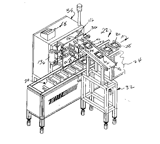
Fig. 1 includes a conveyor 20 which extends beyond
the broken line 24 to any suitable automatic packaging
machine 22. The conveyor 20 carries a plurality of
mandrels, such as 26, for receiving the pouches and
~; 25 carrying them up stream ~Direction A) to an awaiting
carton or box. By way of example, a mandrel 28 is here
shown as so carrying pouch 30.
.
.
,
.
'
,
2 ~ 7 ~
The inventive automatic loader includes a first or
pouch conveyor member 32 and a second or control member
34 which includes a two bin loading device 36. Members
32, 34 are portable and may be moved in any suitable
manner to any suitable locations and used there in
connection with any suitable automatic packaging machine.
The only requirement is that the conveyor 32 is
positioned to drop product into a bin on member 34 and
that the bin is positioned to drop product into a
suitable receptacle in the automatic packaging machine.
The products are asynchronously received by conveyor 32
and are delivered in synchronism with conveyor 20, with a
buffer time storage in bins 36 to coordinate with the
automatic packaging machine time base. Beyond this it is
irrelevant whethex the inventive loader and packaging
machine are aligned one way or another or whether the two
loader parts 32, 34 are on the same or opposite sides of
mandrel conveyor 20.
The conveyor member 32 is self-powered to drive a
conveyor belt 46. Sensors 38, 40 are any suitable
devices, such as a light and photo cell combination, to
stop the conveyor belt 46 and a pouch 42 before it is
; delivered or to start it to be delivered to the bins in
member 34. The equipment which deposits pouches 42, 44
on the conveyor belt 46 is not shown. Any suitable means
may so deposit the pouches; or, they may be manually
loaded onto conveyor 46. Either way, the source of
2~78~
pouches may operate on any suitable time basis including
in a random and asynchronous manner. Thus, the term
"asynchronous" is used herein after to mean any suitable J
timing at which pouches are deposited on conv~yor 46.
The control member 34 of the inventive loader
includes a microprocessor 48 which may be programmed to
command the loader to perform any suitable function. The
automatic packaging machine will deliver signals which
are indicative of its mode of operations. For example,
automatic packaging machines conventionally include many
sensors which detect conditions such as the presence or
absence of a box, or other conditions, having an effect
upon the delivery of a product to a box. The
microprocessor may be programmed to advance conveyor 46
or to unload the bins only if and when a product should
~e delivered to the box. Moreover, the bins may be
programmed to count and deliver one or more pouches to
each mandrel. Suitable microprocessor programs may
eliminate sensors 38, 40 by relying upon command signals
received from elsewhere in the automatic packaging
machine by counting down to stop or start the loader
conveyor 46. Thus, the microprocessor controls the flow
of product to coordinate an asynchronous receipt of
product with a synchronous delivery of product.
Figs. 2, 3 are larger scale drawings taken from Fig.
1, showing the upper and lower bins 50, 52, respectively,
.
~ that are used for delivering the pouches from conveyor 46
. ~
~'
: . . ' :` '
2~78~
to the mandrels 26 on the automatic packaging machine
conveyor 20 with buffer time storage inbetween. Each bin
is defined by two vertical adjustable side plates 54, 56;
58, 60 and by two horizontal bottom blades 62, 64; 66,
68. These plates and blades are arranged to form two
vertically aligned bins 50, 52. The side plates 54-60
are, respectively, adjustably mounted on slide rods 70-
76, for reciprocal motion. By turning knobs 78-84, the
side plates 54-60 may be moved back and forth in the
directions B-I, respectively, to make the bin as wide or
as narrow as required to prealign and deliver the product
pouches.
Each of the slide rods 70-76 has an associated chart
or scale 86 which visibly indicates the positions of the
side plates to facilitate a setting of the widths of the
bins 50, 52. This way, a user may set the machine to
accomplish any suitable pouch ali~nment without
necessarily having to experiment, as by inching the
machine through a work cycle.
The operation is that conveyor 46 drops a pouch into
the upper bin 50 where it rests on closed blades 62, 64.
Then, blades 62, 64 are first moved in directions B, E
and then returned in directions C, D in order to drop the
pouch into lower bin 52 wherein it rests on closed blades
66, 68. This process is repeated any suitable number of
times which have been programmed into the microprocessor
in order to accumulate the number of pouches that are to
. . ,
2~77~
be placed in a single box. After one or a selected
number of pouches have been delivered, the bottom blades
66, 68 move in the directions F, I and then return in the
directions G, H in order to drop the pouch or collected
pouches into the underlying mandrel 26. The invention
provides great flexibility so that a plurality of pouches
may be accumulated in either bin.
Among other things, the two bins provide a time
buffer storage. The pouches 42 are dropped into the
upper bin 50 on an asynchronous time scale which matches
the timing of equipment for supplying the pouches or a
random delivery, as when pouches simply fall out of a bin
and onto the conveyor 46. The pouches on conveyor 46
drop off the end of conveyor belt 46 (Fig. 1) on demand.
The pouches 42 are dropped from the lower bin 52 and into
mandrel 26 on a time scale which matches the timing of
conveyor 20. Thus, within reason, it is not necessary to
closely coordinate the timing of pouch delivery by a
source of pouches fed into the loader 32, 34 and of the
automatic packaging machine 22.
The equipment for controlling the operation of the
blades 62-64 will become more apparent from a study of
Figs. 4-8. Fig. 4 is an exploded view which shows a
single side plate 56, one bin floor blade 64, and the
equipment for moving them. The remaining parts required
to provide the other side plates, floor blades, and
2~778~0
moving equipment are duplicates of the parts shown in
Fig. 4.
The side bin plate 56 has an attached s~cond plate
88 which gives a vertical stability. The slide rods 72
pass through a slide block 90 attached to a front
mounting plate 92 at the screw holes 94. Two slide rods
96, 98 slide through block 90 and are attached to plate
56 and plate 88. Knob 80 turns a feed screw 100 threaded
through block 90 in order to mo~e the side plate 56 o~
the bin in directions D, E to a location indicated by a
scale or chart 86 (Figs. 2, 3).
A guide track 102 (Fig. 4) is attached to the back
of the front mounting plate 92. A preferably nylon
runner 104 is positioned in the track 102 to move back
and forth in directions D, E. Mounted on and moving with
the runner 104 are two carrier blocks 106, 108 which are
bolted to the bottom bin plate 64, which projects through
slot 65 in mounting plate 92. Thus, plate 64 moves back
and forth in directions D, E as the carrier blocks 106,
108 slide on runner 104.
A pla~e 110 is secured between carrier blocks 106, -
108 and bottom bin plate 64. A bearing shaft 112 is an
integral part of the plate 110. Link 114 extends between
the bearing shaft 112 and an eccentric crank arm or wheel
116 in order to convert the rotary wheel 116 motion into
the linear runner 104-106 motion. The crank arm or wheel
116 is mounted on a drive shaft 118 supported by bearing
-
.
': ', ' . . ' . ' . ' , , ' ,' ': ' : . . . , . - , . . . . . -
. : , , :. , , . ., .
2~8~0
lZ~ affixed to a back mounting plate 122. A suitable
collar or nut 124 is affixed on shaft 118 to hold it in
place.
Suitable spacers 126 secure front and back mounting
plates 92, 122 in a spaced, parallel relationship. On
the back of the back mounting plate 122 (Fig. 5), the
shaft 12~ (similar to shaft 118) includes two pulley
wheels 12g, 130, each of which preferably has teeth
engaging the teeth on timing or drive belts 132, 134,
respectively. Any suitable motor 136 turns a driving
pulley 138 which causes pulley 130, and therefore, drive
shaft 128, to turn far enough through an arcuate rotation
reguired to open and close the bottom bin plates 62. The
drive shaft 118 controls the other bottom bin plate 64
via pulley 129, timing belt 134, pulley 124, and shaft
118. In a similar manner, motor 142 controls the bottom
plates 66, 68 of lower bin 52 via timing belts 144, 146
and drive shafts 148, 150.
Figs. 9 and 10 illustrate one example of an
adjustable mandrel which may be used to receive and
package the irregularly shaped pouches.
The product in the mandrel tray 150 includes, by way
of example, three individually wrapped tubes 152, 154,
156 of soda crackers. Owing to the nature of the
product, the three tubes do not have a closely controlled
cross-section. The crackers may be misaligned so that
each tube is, for example, an ~ighth of an inch wider
,~
. . . .
: .. '' ' ' , . ' . : :
''
o ~
13
than it should be, thus making an accumulated three-
eighths of an inch of excess width. Also, depending upon
where the misaligned crackers are located, there might be
a much greater than normal width. The sides of the tubes
may be rather irregular so that the same three tubes
would not always fit together in the same way. This is
shown in Fig. 9, where the tube of crackers 156 does not
~it down and into mandrel tray 150. Downstream in the
automatic packaging system, the out of position tube 156
may cause the system to jam.
It will be observed that, in Fig. 9, there is a
substantial overlap 158 of the bottoms of mandrel tray
sides 157, 159, which means that the tray is narrow so
that the three tubes 152-156 of crackers must fit almost
perfectly if they are to rest in side by side positions.
,..
; In Fig. 10, the tray 150 has been made much wider.
Note the small overlap at 158 of the bottoms of the two
tray sides 157, 159. Thus, there is not enough space
within the tray 150 to receive the tubes 152-156 of
crackers in a side by side relationship with a
substantial space 160, 162 between them. As the tray
; moves from a loading position to a packaging position and
becomes more narrow, the sides 157, 159 may move together
to take up the space 160, 162 and make the tubes 152, 156
fit into a box as the tray 20.
':
': :
`: :
.
.. . .. . . . . .
- - '' ' ' : ," . ' .'....... : '
.. , . , :, : ~ ~ -
. .
.. ~ . , - . . . .
- - . . .
~7~
14
Fig. 11 is an exploded view of the man~rel tray.
The mandrel tray 150 is comprised of two sheet metal side
members 157, 159 (with a generally "L-shaped" cross-
section) which slidingly fit over each other in the
bottom region. Two bars 168, 170 are attached to the
bottoms of tray halves 157, 159 to provide anchor points
and, also, to provide strenqth and rigidity to the trays.
A pair of guide rails 172, 174 are held in a spaced
parallel relationship by a support bar 176. Four nylon
bearing blocks 178-184 are mounted to slide along the
rails 172, 174. The side bars 168, 170 are mounted on
the nylon bearing blocks 178-184 so that they may slide
back and forth in directions J, K.
An eccentric crank or rotary member 186 is mounted
to rotate in a space which is always at the center of the
tray, regardless of its width. Pivotally mounted on and
extending between rotary member 186 and side bars 168,
170 are two lever arms 188, 190. When the rotary member
54 turns one way (Direction L), the sides 157, 159 of the
tray are pulled in by lever arms 188, 190 to reduce the
tray width. When the rotary member 186 turns in an
opposite direction (Direction M) the lever arms 188, 190
push out the sides 157, 159 of the tray and make it
wider.
The support bar 176 has a journal 192 into which
bearing 194 and an axle 196 may fit in order to rotatably
support the rotary member 186. Rotary member 186 is
:.
~ ',`.' " ' ' ~'
2~77~
fixed to the upper end of axle 196. On the opposite or
lower end of the axle 196 is fixed a cam plate 198~ A
cam follower roller 200 has an axle that fits into a hole
202 in the bottom of cam plate 198. The ends of side
bars 168, 170 are mounted on four nylon bearing blocks
178-184 which fit over rails 172, 174. Therefore, as the
cam follower 200 turns rotary member 186, the lever arms
188, 190 move, the tray side members 157, 159 slide back
and forth on the rails 172, 174.
A pair of conveyor chains 204, 206 are, broadly
speaking, about the same as conveyor 20 of Patent
4,829,751. They carry the mandrel 150 formed by the tray
sides 157, 159 along a predetermined path represented by
arrow N. A plate 208 extends between conveyor chains
204, 206 and is bolted thereto by way of brackets 210,
212. Also mounted on brackets 210, 212 are slide bars
supports 214, 216. Spaced, parallel slide bars 218, 220
extend between supports 214, 216. A sliding member 222
slides back and forth (Directions P) on the bars 218,
219. The rotary member 186 has an axle 196 which fits
through hole 224 in block 222 and slides within slot 226
in plate 208. Thus, the cam follower 200 has a
continuous control over the rotary position of member 186
and, therefore, the width of the mandrel 150 throughout
the entire excursion (Direction N).
Fig. 12 includes six stop motion views showing the
operation or work cycle of the inventive system. Figs.
. : ' . ' -
~- ' , ' ' ' ~
':
~7~
16
12A shows the upper and lower bins 50, 52 with the side
plates 54-60 being adjusted in directions B-I to provide
a bin width selected to receive and preposition a
particular size of pouch.
Fig. 12B shows that the pouch 42 (Figs. 1, 2) has
been deposited in upper bin 50 and is supported by bottom
bin blades 62, 64. One or any suitable number of pouches
may be accumulated for inclusion in a box. If only one
pouch is deposi~ed in a box, some of the steps shown here
may be omitted.
Fig. 12C shows an exemplary case where two pouches,
which are to be placed in a single box, are accumulated
in upper bin 50. Thus, a second pouch 44 is placed in
upper bin 50. To provide a specific example, pouch 42
might be a pouch of rice and pouch 44 might be a pouch of
chop suey, both of which may be placed in the same box
and then frozen. Also, the system may be programmed to
accumulate pouches in either the upper or lower bins 50,
52 according to particular packaging needs. As here
shown, by way of example only, the two pouches are
initially accumulated in the upper bin. In another
situation, two or more pouches might have been initially
accumulated in the lower bin 52.
Fig. 12D shows the bottom bin blades 62, 64 have
been moved in directions B, E to drop the pouches 42, 44
into lower bin 52, and then returned in directions C, D
; to close the bottom of the bin. The next incoming pouch
: .
: . : . - : -
: . ~ , . . .
' ' ' ~ .' ,, :- . ' '' . '~ . " '' , : - '
~778~9
230 has been dropped into upper bin 50. In a relatively
wide configuration, mandrel 26a is moving into, but has
not yet reached, a loading position. Meanwhile, upper
bin bottom blades 62, 64 have moved back in directions C,
D to prepare bin 50 for the next drop. The sensors 38,
40 (Fig. 2) release the next pouch 2io on conveyor 46 for
delivering a pouch on demand to upper bin 50.
Fig. 12E shows the wide mandrel 26a directly under
the lower bin 52. The lower bin bottom blades 66, 6~
move outwardly in directions F, I to drop pouches 44, 42
into the wide mandrel 26a. Fig. 12F shows that the
bottom plates 66, 68 have returned in directions G, H
while mandrel 26a is taking pouches 44, 42 to a work
station where they will be deposited into a box. At this
time, mandrel 26a is becoming more narrow, shaping and
pushing the pouches 44, 42 into a configuration where
they will fit into the box. The next mandrel 26b is
moving into position to receive the next pouches. The
; two bins have returned to the step in the work cycle,
that is also shown in Fig. 12C.
The blades forming the bottoms of the bins may be
given an oscillating motion in order to shake a product
out of the bin if it has a characteristic which makes it
hard to unload~
The bins 50, 52 may be mounted to move a short
distance over the mandrel 26 as it moves, returning to a
~ .
2~7780~
18
start position before attempting to deposit a pouch in
the next following mandrel.
It should be noted from Figs. 12D and 12E that the
lower bin 52 provides a time buffer for enabling the
mandrel 26 to be positioned. Thus, the loader may
asynchronously load into upper bin 50 while the mandrels
of the automatic packaging machine receive product from
bin 52 at its timing. These two timings do not have to
be synchronized.
Those who are skilled in the art will readily
perceive how to modify the invention. Therefore, the
appended claims are to be construed to cover all
equivalent structures which fall within the true scope
and spirit of the invention.
. ~
.