Note : Les descriptions sont présentées dans la langue officielle dans laquelle elles ont été soumises.
-
8~4~ ~
~GNETIC INSPECTION MACHINE
The invention relates to magnetic inspection machines.
Magnetic inspection machines in the form of vehicles are used for inspecting
the condition of pipelines and in such vehicles magnetic flux from permanent
magnets or electromagnets is passed into and returned from the surrounding
wall of the pipeline through steel bristles srranged in brush-like groups
which sweep along the inside surface of the pipeline wall as the vehicle
passes through the pipeline.
Each brush-like group of bristles comprises one or more relatively thick
steel plates each having a set of holes. In each hole a tuft of steel
bristles is secured. We have found that foils can be used instead of
bristles and that for a given volume more metal is present when foils are
used compared with the use of bristles. Also, the foils are secured by
clamping them between members which allows the foils to be replaced without
the need to replace plates corresponding to those on which the bristles are
mounted.
Early proposals regarding foils are given in our British Patents
Nos. 2034122 and 2086051. They explain that bristles or foils are required
to be kept in contact with the wall of the pipeline despite variations in
its internal diameter along its length.
Also, at least part of the weight of the vehicle and the forces due to
movements of the vehicle transverse to the length of the pipeline are
counteracted by the reactions between the pipeline wall and those bristles
or foils which are forced towards the wall by the weight or other forces.
As explained in those patents the proportion of the weight or such other forces
imposed on the bristles or foils depends on the design of the vehicle.
In British Patent No. 2,034,122 the variations in the internal diameter of the
pipeline wall are accomrnodated by mounting the foil sets in pairs on respectivemagnetic return-path members, each member being connected to the body of the
pig by springs.
In British Patent No. 2,086,051 the foils are described as being secured in fixed
relationship to a cornmon body member of the vehicle. However, the foils are
described as being of the same kind as those disclosed in British Patent No.
2,034,122.
In British Patent No. 2,034,122 several foils are shown as integral parts of a
common member 8. The foils are formed by slitting the comrnon member at slits
11. The slits do not provide any clearance between neighbouring foils.
Foils can also be used in a magnetic inspection vehicle which is used to inspect the
condition of tank floors and can also be used in a magnetic inspection m~ehine
which is used to inspect the condition of plates by relative motion between the foils
and plates. In this specification the word "machine" means magnetic inspection
machines in which plates are inspected and magnetic inspection vehicles for
inspecting pipelines or for inspecting tank bases or floors.
According to the present invention there is provided in a magnetic inspection
machine constituting a first means and intended for progressively inspecting a
workpiece constituting a second means during relative movement between said
first and second means, a foil assembly for eng~ging the workpiece during said
relative movement, said foil assembly comprising two groups of foils having tipswhich are intended to engage the workpiece and the groups being coupled
magnetically at the ends of the foils remote from the tips to a source of magnetism,
r ~
the foils being resiliently deflectable in a first direction transverse to the plane of
the foil, each foil in each group being spaced from a neighbouring foil in said first
direction by an intervening space and each foil in each group being separated from
a neighbouring foil in a second direction transverse to said first direction by an
intervening space allowing the foils to move closer to one another upon deflection
of the foils caused by the distance between the first means and second means
becoming less.
The present invention further provides, in a magnetic inspection m~hin~constituting a first means and int~nded for progressively inspecting a workpiececonstituting a second means during relative movement between said first and
second means, a foil assembly for engaging the workpiece during said relative
movement, said foil assembly comprising two groups of foils having tips which are
intended to engage the workpiece and the groups being coupled magnetically at the
ends of the foils remote from the tips to a source of magnetism, the foils beingresiliently deflectable in a first direction transverse to the plane of the foil, each foil
in each group being spaced from a neighbouring foil in said first direction by an
intervening space and each foil in each group being separated from a neighbouring
foil in a second direction transverse to said first direction by an intervening slot,
said groups of foils each comprising a plurality of common foil members, said
common foil members each being integral with a plurality of foils and being
annular in shape, and said common foil members being spaced apart by interveningspacers so as to provide said intervening space between neighbouring foils, eachcommon foil member in each group being frusto-conical in shape.
Embodiments of the invention will now be described by way of example with
reference to the accompanying drawings, in which:
Figure 1 is a vertical, longitudinal section through a first embodiment,
~ 2 ~
-3a-
Figure 2 is an elevation of foils used in the first embodiment;
Figure 3 is an edge-view of the foils shown in Figure 2;
Figure 4 is an elevation of a spacer used in the first embodiment;
Figure S is an edge-view of the spacer shown in Figure 4;
Figure 6 shows a second embodiment;
Figure 7 is a vertical, longitudinal section through a third embodiment;
Figure 8 is a scrap vertical section through a set of foils, shown
undeflected, used in the third embodiment;
-- 4 --
Figure 9 is a scrap elevation of the set of foils shown in Figure 8
Figure 10 is a vertical longitudinal section through a fourth
embodiment;
Figures 11 and 12 are, respectively, an elevation and an edge view of a
foil used in the embodiment shown in Figure 10; and
Figures 13 to 15 are scrap views of the foils and further illustrate
the condition of the foils under increasing deflection.
Figures 1 to 5 show a magnetic inspection machine in the form of a pipeline
inspection vehicle for inspecting ductile cast iron gas distribution
pipelines, in this case 12" pipelines (ie pipelines having nom;n~lly a 12",
300 millimetre inside diameter). The invention is applicable to vehicles
for inspecting different sized pipelines, eg 6" and 8" gas distribution
pipelines, and also steel gas transmission lines having inside diameters of,
say, 6" and above. The invention is also applicable to vehicles for
inspecting non-gas pipelines, such as steel water or oil or other pipelines,
for example.
In this example, the pipeline is inspected while it is "dead",ie without any
gas being present in it,and the vehicle is intended to be pulled through the
pipeline by a cable attached to a winch. In transmission lines, the vehicle
would normally be equipped with cups engaging the pipe wall and the vehicle
would be propelled by a difference in pressure (developed across the cups)
in the product being conveyed by the pipeline.
2080~47
Other drive options which are possible include the use of a tethered vehicle
driven by drive cups engaging the pipe wall (eg the vehicle could be
tethered by the umbilical cable). The pressure difference across the cups
may be due to air or other fluid blown along the pipe, in the inspection of
"dead" pipelines, or where the pressure would be high enough the pressure
difference across the cups could be due to gas moving in the pipeline as in
medium pressure (and higher) distribution lines; also included is the use of
a tractor vehicle to pull the inspection vehicle or to have inspection
facilities included in the tractor vehicle. A tractor vehicle is usable in
gas distribution lines, gas transmission lines, and water or oil or other
lines.
In further variations, tractor vehicles can react against the pipe wall, or
react against a stationary "prelaid" cable if the pipewall cannot tolerate
reaction forces.
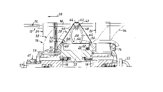
In Figure 1, the minimum bore of the pipeline 10 is shown at 12 and the
~ bore of the pipeline 10 is shown at 14. The pipeline 10 is made of
ductile cast iron and the bore varies between the maximum and ~n; values
shown.
The vehicle 16 consists of the following main components: a body 18; an
electro-magnetic coil 20 wound on a former 22; groups of foils 24, 26; and
thirty-six sensor assemblies 28 (only one of which is shown) equiangularly
arranged around the body 18 of the vehicle 16.
Each group of foils 24, 26 is made up of a number of common foil members
59 each having the shape shown in Figure 2. This shape preferably comprises
twelve foils 25.
- 6 - 20804~7
The use of foils gives a major advantage in that it allows a smaller
occupied volume given the required metal area for adequate flux transmission
into the pipe wall. In this specification each of the groups 24, 26 is
referred to by the expression "flux conductor". The function of the groups
of foils 24, 26 is explained below.
The vehicle in this case runs on the groups of foils without any other
suspension component engaging the wall of the pipe. Alternative forms of
vehicle may use wheels on the vehicle running along the pipewall in order to
support all, or some of the weight of the vehicle. The wheels may be
displaceable relative to the body against springs. Instead of, or in
addition to, wheels the weight of the vehicle may be partly or wholly
supported on the drive cups referred to above.
Each assembly 28 comprises an austenitic stainless steel sledge 40 which is
secured to a sensor housing 42 with a length of belting 44 sandwiched
between the two. The end portions of the belting 44 form a leading member
46 and a trailing member 48 which link the leading and trailing ends,
respectively, of the sledge 40 to the vehicle. The belting 44 is made of
polyurethane coated polyester fibres and is substantially inextensible.
The ends of the members 46, 48 are each held by a screw 50 which has a
rounded head and retains a washer having a rounded edge portion against the
belting 46 or 48. The screw 50 retains the member 46 or 48 against a
stainless steel pressing 58 forming a base plate, itself retained in
position on the outer edges 60, 62 of the former 22.
The assembly 28 i5 positioned against a spring 64, which is also positioned
against the vehicle, or rather against the respective pressing or base plate
58. The spring 64 is approximately of 0 form and is made of polyurethane
elastomeric material. The spring 64 has a flattened shape at 66 where it
engages the base plate 58. The spring 64 is retained in position against
the base plate 58 by a pin 68 which engages holes in the sides of the plate
58, which is of U-section. The spring 64 is retained at its opposite end by
ears 70 formed on the sensor housing 42, the ears 70 extending one on each
side of the spring 64 to retain it against sideways displacement normal to
the plane of the spring 64.
The inspection vehicle 16 is shown in the condition which applies to the
vehicle before it is inserted in the pipeline. Assuming the vehicle is
intended to move in the direction of the arrow 30 shown in Figure 1, when
the vehicle 16 is inserted in the pipeline the foil groups 24, 26 would be
deflected to the right so as to curve as indicated by the ghost outlines at
32 and 34.
The assemblies 28 would also be deformed,and while the vehicle 16 is
stationary in the pipeline the members 46, 48 are slack~and only the spring
64 is effective to exert a force on the sledge 40 which is substantially
normal to the wall of the pipeline.
~hen the vehicle 16 moves (say in the direction of the arrow 30 shown in
Figure 1) the leading member 46 becomes taut and the motion of the vehicle
is transmitted to sledge 40 by the member 16. The trailing member 48
becomes slack and does not play any part in the control of the assembly 28
so long as the sledge 40 runs along the inside of the pipewall.
When the sledge 40 travels across a void in the pipework (for example where
a branch pipe joins the pipeline) the sledge 40 moves radially outwardly and
both leading and trailing members 46, 48 act to exert inwardly directed
forces on the sledge 40 to counteract the outward force of the spring 64.
The vehicle 16 is designed to travel backwards, should it prove impossible
to move it forward. In that case, the roles of the members 46, 48 are
reversed. The foil groups 24, 26 would be deformed in the opposite sense,
curving towards the left instead of towards the right.
Each assembly 28 must accommodate variations in the bore of the pipeline 10
and side-to-side motion of the vehicle within the pipeline. Furthermore,
the vehicle is required to negotiate bends in the pipeline. Such bends may
be as tight as one diameter, that is the radius of curvature of the bend
(measured to the pipe centre) is equal to the internal diameter of the bend.
Such a bend is especially severe in the case of 6" pipe. This is shown in
Figure 6 in which a 6" vehicle is shown negotiating a one diameter bend in a
distribution pipeline. The assembly 28 at the inside of the bend is shown
in the condition it has when the vehicle is outside the pipeline, however.
In negotiating such a bend the sensor assembly 28 at the inside of the bend
is required to collapse completely. This is possible owing to the nature of
the leading and trailing members 46, 48. Under such conditions, the foil
group 24 at the inside of the bend would be required to be deflected right
over until the rearmost foil 25 lay against the stop 71 (shown in Figures 1
and 6) carried by the vehicle body 18, and against the upper edge 72, of the
wings of the pressing 58. The foil group 26 would be heavily deformed,
adjacent to the outer wall of the pipeline, and the rearmost foil 25 would
conform to the stop 74 (shown in Figures 1 and 6) carried by the vehicle
body 18.
t
2080447
Under certain conditions, the spring 64 might engage the leading member 46
and the trailing member 48.
For example, the size of the pipe might demand a spring of such
characteristics that the spring occupies nearly the whole of the space
between the leading member 46 and the trailing member 48. Under running
conditions in the pipeline 10 the spring 64 might cause the leading member
46 to bow outwards.
However, even under such conditions the spring still exerts a force on the
sledge 40 which is substantially normal to the pipewall. Also, the motion
of the vehicle is still transmitted to the sledge 40 by the leading
member 46 notwithstanding its bowed shape.
As shown, the vehicle 16 is intended normally to travel in the direction of
the arrow 30 shown in Figure 1, being pulled by a haulage cable (not shown)
attached to a swivel assembly 61 mounted on a pin 57 secured to the leading
end of the body 18. Another haulage cable (not shown) for retrieving the
vehicle 16 in reverse is attached to the eye 55 secured to the trailing end
of the body 18.
The inspection is carried out using the flux leakage method. A powerful
magnetic field is generated by the electromagnetic coil 20 and transferred
into, and out of, the wall of the pipeline 10 by the foil groups 24, 26.
Electric current to energise the electromagnetic coil 20 is supplied from
the surface via an umbilical supply cable (not shown) connected to the coil.
Defects, such as loss of metal due to corrosion in the wall of the pipe,
cause magnetic flux to leak out of the wall of the pipe and this is detected
by the sensor within the housing 42. Each sensor transmits a continuous
- lo - ~ 4 ~ ~
signal as the pig moves through the pipeline,and this signal, with the
signals from the other sensors, is sent down a second umbilical cable (not
shown) which extends from the vehicle to a personal computer with a hard
disc recording facility at the surface of the ground. The position of the
vehicle along the pipeline is known from a monitor measuring the length of
haulage cable paid out by the winch.
The vehicle does not inspect the condition of the pipewall as the vehicle
negotiates l-D bends, for example as shown in Figure 6. However, for larger
diameter bends where the sensors are able to run along the pipewall
throughout the bend a full inspection is carried out. This will apply to
most transmission pipeline inspections. It is only in distribution
pipelines where l-D and similar very tight bends are encountered that no
inspection will be carried out in the region of the bends.
In some cases (for example where an umbilical supply cable cannot be used)
the electromagnetic coil 20 is replaced by a permanent magnet or magnets.
The magnetic flux created by the electL~ a~net 20 circulates in a path,
which includes the wall of the pipeline 10, the flux contuctor or foil group
26, the return path provided by the body 18 and the other foil group 24
forming the other flux conductor.
In other modifications (not shown) the path may include flux return paths
which are formed by members carried by the body, instead of the body itself
providing the return path. For example, where permanent magnets are used
instead of an electromagnet, the arrangement may be as shown in British
patent specification No. GB-B-1535252. In that specification the magnets
are flat plates having the magnetic poles at their broad faces and those
i
c
'~J ~
faces are arranged parallel to the pipe inside surface. The magnets are
arranged one at each end of flux return path members arranged around the
body. The members are mounted on springs so as to move radially inward and
outward to allow changes in diameter of the pipeline to be accommodated.
The flux conductors are mounted upon the magnets. The assemblies 28 would
in that arrangement be mounted not on the body itself but on a ring which is
"floating". That is, the ring surrounds the flux return path members and is
connected to them by radial posts which pass through holes in the ring. The
ring can thus move radially with respect to the flux return path members as
the vehicle negotiates bends.
Each group of foils 24, 26 consists of 90~foils each as shown in Figures 2
and 3. Each common foil member 59 is an annulus cut from sheet stainless
ferritic or martensitic steel 0.3 mm thick, in this example. The overall
diameter of each common foil member 59 is 345 mm in the undeflected
condition of the common foil member 59. The groups of foils 24, 26 are
shown undeflected, in full lines, in Figure 1 and are also shown deflected
as indicated by broken lines, 32.
Each common foil member S9 has twelve resiliently deflectable foils 25
separated by V-shaped intervening slots 63, the angle between adjacent
fingers being 30 degrees. The central aperture 65 in each common foil
member 59 has a n~: nAl diameter of 90 mm. Each group of foils 24,26 is
located by the body 18 which extends through the central apertures 65ofthe
common foil member 59. In each group of foils 24, 26 adjacent common foil
members 59 are separated by a single A~nlllAr spacer 69 shown in Figures 1, 5
and 6. In this example, each spacer 69 is cut from the same sheet material
as is used for the common foil members 59 and the external diameter of each
spacer 69 is 125 mm. The internal aperture has a n- nAl diameter of 90 mm.
12 r~
In esch group of foils 24~ 26 there is a pin 67 extending through holes 75
in the group. A retainer 73 retains the pin 67 ant the group in position on
the body 18.
Each spacer 69 is 0 ~ 3 mm thick. Thus, in this example, the quotient formed
by dividing the separation of adjacent common foil members 59 in each
group 24~ 26 by the thickness of each common foil member 59 is unity. That
quotient may be termed the "packing density".
The invention can be performed using foils and spacers of thickness
different from the values quoted above by way of example. However, it is
preferred that the packing density be equal to or greater than unity and it
is particularly preferred that the packing density shall be in the range of
from unity to two.
On an 8 inch vehicle the common foil members 59 (ie the foils 25) are
preferably made from material which is 0.15 mm thick and the spacers 69 are
preferably of the same thickness. On a 6 inch vehicle the common foil
members 59 (ie. the foils 25) are preferably made from material which is
0~075 mm thick and the spacers 69 are preferably of the same thickness. For
an 8 inch vehicle there are preferably twelve foils on each common foil
member 59t arranged equidistantly around the vehicle. The 8 inch vehicle
preferably has twenty-four sensors. For a 6 inch vehicle there are
preferably nine foils 25 on each common foil member 59, arranged
equidistantly around the vehicle. The 6 inch vehicle preferably has
eighteen sensors.
The outer edge of each spacer 69 just overlaps the innermost apices of the
V-shaped slots 63 in the two adjacent common foil membersS9inthe
13 F
groups 24, 26 so that the free length of each foil 25 is 110 mm. The
quotient formed by dividing the length of a foil 25 by its thickness in this
example is 366. That quotient may be termed as the "slenderness ratio" of
the foil. The invention can be performed using foils having dimensions
different from those quoted above by way of example but it is preferred that
the slenderness ratio be generally greater than 300. This is to avoid
yielding of the material of the foil at large deflections.
The common foil members 59 in each group 24, 26 are arranged with their
foils 25 aligned in trains 82. Each group 24, 26 accordingly comprises
trains 82 of foils 2~ separated by the aligned slots 63. Whilst it is
preferred to have all the foils or at least most of them aligned in trains
it is not essential,and in other embodiments of the invention different
arrangements can be used.
Whatever the arrangement, each group of foils comprise foils which form an
array extending around the vehicle.
The first embodiment described above is intended for use in inspecting
cast-iron natural gas distribution pipelines. The vehicle is pulled through
the length of pipeline being inspected using a tow member
attached to a winch (not shown). The pipeline length is "dead" (ie no gas
is flowing) during the inspection. The coil 20 is energised and produces
magnetic flux which is conducted into the wall 10 of the pipeline and
conducted back to the coil by the foil groups 24, 26. The groups are
deflected as indicated in ghost outlines 32, 34 in Figure 1 and slide along
the inner surface of the wall 10. Loss of metal from the wall 10 owing to
corrosion causes magnetic flux to leak from the wall 10 and the sensors 28
- 14 -
produced signals accordingly as they respond to the leakage flux. The
signals pass to recording equipment (not shown) via an umbilical cable (not
shown). Power is fed to the coil 20 via a power cable (not shown).
A second embodiment of vehicle is shown in Figures 7 to 9. The vehicle is
intended to be used for "on-line" inspection of a transmission pipeline,ie a
pipeline which is conducting natural gas or oil or some other product under
pressure. Typically, for example, such a pipeline has an internal diameter
varying in the range 416 to 446 mm and the vehicle would be used in train
with one or more other vehicles making up a "pig". The pig is moved through
the pipeline by the pressure difference developed across the pig by the
fluid flowing in the pipeline. ~or example, one of the vehicles in the pig
train can be fitted with rubber seal cups which slide along the inside
surface of the pipeline and the pressure difference across at least one cup
propels the pig.
The vehicle comprises: a solid body 90 of mild steel; two sets of permanent
magnets 92, 94 each magnet being secured to a flat face of a
hexagonal-shaped end portion 96, 98 of the body 90; and two groups of
foils 100, 102 secured to the magnets 92, 94, respectively.
Magnetic field sensors, which would be mounted on the vehicle,have been
omitted from Figures 7 to 9.
Each group of foils 100, 102 is made up of six sets 104 of common foil
members (Figures 8 and 9). Each set 104 comprises in this example 175
common foil members 106 clamped together with intervening spacers (not
shown) which each have the same outline shape as one of the clamp
- 15 -
blocks 108. The common foil members 106 are clamped between the block 108
and a second block 110 by bolts 112 and nuts 114, together with tapered end
spacers 116.
Each common foil member 106 is sector-shaped and comprises five integral
resiliently deflectable foils 120 separated by V-shaped slots 122.
Typically, in this example, the width of the narrower, lower end of each
common foil member 106 is 140 mm and the maximum free length of each foil
120 is 110 mm. The common foil members 106 and spacers are each
0.3 mm thick. The packing factor is thus unity and the slenderness ratio
is 367. The angle between the two outermost foils 120 is 48 degrees and the
angle between adjacent foils is 12 degrees. When the six sets 104 are made
up into a group 100 or 102 of foils the angle between the adjacent
foils 120 in adjacent sets is also 12 degrees. The distance between the
leading the trailing ends of the set of foils shown in Figure 8 measured
between the tapered spacers 116 is 105 mm.
The clamping blocks 108, 110 are secured to the magnets 92 or 94.
The foils are shown undeflected in Figures 8 and 9. Each group of
foils 100, 102 comprises common foil members 106 which form an array
extending around the vehicle. In this example the foils in each group are
arranged with the foils 120 aligned in trains 130 separated by the aligned
-Qlots 122. However, as already explained, that is not essential.
The common foil members 106 in this example are inclined in each group 100,
102 so that their outer ends are positioned, even in the undeflected
condition, rearwardly with respect to their inner ends in relation to the
- 16 -
direction of forward motion of the vehicle indicated by the srrow in
Figures 7 and 8. Such sweeping back of the foils 120 is preferred but it is
not essential. It is a design option which can be used to reduce the drag
imposed by the foils on the vehicle.
Figure 7 shows the foils in the groups 100, 102 deflected by engagement with
the wall 140 of the pipeline. Generally, in any embodiment, it is preferred
that in the working range of deflections the radial strain to which the
foils are subjected is up to 30X, depending on the packing density. The
radial strain is defined as the quotient X~L100X, where L is the free
undeflected "height" of the foil as indicated in Figure 8 and X is the
difference between L and the deflected height of the foil.
In the third embodiment shown in Figures 10 to 12 the vehicle is typically
for example intended for use in inspecting a transmission pipeline of
nominally 204 mm (8 inches) internal diameter. The vehicle has a body made
up of two solid cylindrical mild steel parts 160, 162 with an annular
permanent magnet 164 between them, the assembly being held together by
bolts 166. The vehicle has two groups of foils 168, 170,each group
comprising a single common foil member 172 (Figures 11 and 12). Each common
foil member 172 is AnnUlAr and is located on a reduced diameter portion 174
or 176 on the body parts 160, 162. The magnetic field sensors which would
be mounted on the vehicle have been omitted from Figures 10 to 12.
The groups of common foil members are clamped, with intervening Annul~r
spacers (not shown) which also encircle the reduced diameter portions,
between shoulders 178, 180 on the parts 160, 162, respectively and
rings, 182, 184. Each ring 182, 184 encircles the reduced diameter
c
~j
2080447
- 17 -
portion 174 or 176 and is forced against the group of common foil members by
three screws such as the one shown at 186, the screws 186 being mounted in a
further ring 188 or 190 qecured to the relevant body part 160 or 162 by
bolts 192 or 194.
Typically, in this example, each common foil member has a central aperture
of 85 mm diameter and comprises twelve integral resiliently deflectable
foils 196 separated by V-shaped slots 198. Each common foil member
typically is cut from ferritic or martensitic stainless steel sheet 0.125 mm
thick and the spacers (not shown) are cut from the same material. The
packing density is thus unity. Any suitable material can be used for the
common foil members, including mild steel.
The apices of the slots 198 coincide with the r~X;mlm diameter of each
shoulder 178, 180 and of each ring 182, 184 such diameter being indicated by
a broken line 200 in Figure 11. Such diameter in this example is 115 mm.
The overall diameter of each common foil member 172 is typically in this
example 235 mm and the foils 196 are each indicated at an angle of
15 degrees to the plane of the inner annular part 202 of the common foil
member 172. The groups of foils 168, 170 are arranged so that the outer
ends of the common foil member 172, even in their undeflected condition as
shown in Figures 10 to 12, are positioned rearwardly with respect to their
inner ends in relation to the direction of forward motion of the vehicle
indicated by the arrow in Figure 10.
When the vehicle is in its pipeline the groups of foils 168, 170 will be
swept rearwardly in a manner analogous to that shown in Figure 7.
- 18 -
The length of each foil 196 in this example is 60 mm. The slenderness ratio
is 480 mm. The foils are arranged in each group 168, 170 with the
foils 196 aligned in trains 210 (Figure 10) separated by the aligned
slots 198. However, that is not essential.
The vehicle shown in Figures 9, 10 and 11 is intended for use in train with
at least one other vehicle (not shown) to form a pig. The pig is propelled
through the pipeline by fluid pressure difference developed as explained in
relation to the second embodiment.
In each of the embodiments described above the foils support the whole of
the weight of the vehicle,and when the pig is travelling along the pipeline
the foils are also subject to the reaction forces arising at the pipe wall
owing to the movements of the vehicle in the pipeline.
In other embodiments (not shown) the foils may be required to support less
than the entire weight or less than the full amount of such reactions from
the wall, depending on the design of the vehicle.
However, in all embodiments the invention enables the available volumes to
be efficiently used by the foils to transfer flux to and from the pipe wall.
For the same suspension performance (ie support of some or all of the
vehicle's weight and the wall reactions) relatively more metal to transfer
flux can be accommodated in the available volume, so giving improved
magnetic performance compared with steel bristles. Conversely, the vehicle
has an improved bend passing performance (the vehicle being relatively
short) with the same magnetic performance.
2080~7
-- 19 --
Design changes can be readily made. Foil replacement is simple and it is
unnecessary to replace heavy plates such as form part of bristle brush
assemblies. The force~deflection characteristics of the foils can be
accurately predicted compared with bristles, for which empirical methods
have to suffice.
Foils provide a path for flux from and to the magnet and can provide a
suspension for the vehicle as well. Compared with bristles, they provide
those features in less space for the same magnetic and suspension
performance. This is important especially in vehicles for pipe inspection
where high bend passing performance is a requirement. Compared with
bristles, the foils behave in a more analytically predictable manner,
because of foil independence. Foils are cheaper and more easily adjusted or
tuned for a specific pipe bore range, and to suit a specific magnetic
circuit, than are bristles.
The ratio of foil spacing to foil thickness controls the radial deflection
(assuming the foils are mounted on a pipeline inspection vehicle) at which
one foil comes into contact with its neighbour. This is a critical point
beyond which all the foils "wedge up" giving an airgap to the pipe wall
behind the leading foil. This effect is to be avoided during the normal
inspection run of the vehicle. However, the effect is beneficial where the
vehicle encounters a restricted pipe bore ("crash bore") because the
magnetic drag is reduced by the air gap created. Within the normal bore
range the suspension design must keep radial compressions of the foils well
below this critical compression value.
2080~47
- 20 -
By comparison, individual wire bristles within tufts of bristles tend to
interfere with their neighbours right from zero radial deflection values,
giving inherently poorer magnetic circuit completion. A ratio of foil
spacing to foil thickness of 1:1 gives foil independency up to around 30%
radial compression.
The extra drag caused by magnetic clamp forces at the foil tip cause a
stiffening of the radial force/deflection characteristic. On "sweeps brush"
inspection vehicles, this subtlety can be utilised to reduce overall vehicle
drag by allowing the use of thinner foils. The magnetic drag helps to hold
the vehicle up. Foils have the advantage of being viable in thinner
sections, and this stiffening effect is more marked the greater the
slenderness ratio. The designer hence has more scope with foils.
To avoid yielding over the relatively large deflections, a slenderness ratio
of around 300 or more is necessary for ferritic materials.
Preinclined foils (optimally around 30 degrees), can further reduce base
levels of drag without much change in stiffness (for the same initial radial
reach). Where low drag is important this is worth doing. However, drag
versus bore is not improved.
The invention is also applicable to inspection vehicles used for inspecting
the condition of tank floors or bases. Where the tank floor is uneven the
foils are required to yield or recover in a direction normal to the tank
floor. This is what was referred to as radial compression or recovery in
- 21 -
the case of a pipe inspection vehicle. Where the tank floor is made up of
overlapping plates, the foils are required to yield and recover to
accommodate such unevenness.
The invention is also applicable to magnetic inspection machines in which
the magnet and foils assembly is moved over a plate which is to be
inspected, or else the plate is moved past the magnet and foils assembly.
Figures 13 to 15 show foils of the swept back kind (see Figures 7-9 or
Figures 10 to 12 for example). However, the following remarks would apply
equally to foils which are planar in their undeflected state.
The figures show for illustration just two of the foils 300, 302 having tips
304, 306 which engage the workpiece 308, which may be the wall of a pipe or
the base of a tank or a plate, depending on which machine is in use. The
height of the foil in its undeflected state is "L". The thickness of the
foil is "t" and the spacing between adjacent foils is "s".
Figure 13 shows the foils in their undeflected state. Figure 14 shows the
foils when they have been deflected sufficiently for the tip 306 of one
foil 302 to just engage the other foil 300. The angle "A" between the
workpiece 308 and the tip 304 (which is the same for each foil) is then
critical for the group of foils. Any further deflection leads to the
position shown in Figure 15.
- 22 -'
In Figure 15 all of the foils in a group have "wetged up" and the only foil
which makes contact with the workpiece 308 is the leading foil, at 310. The
r~m~;n;ng foils are lifted clear of the workpiece 308 and an airgap 312 is
introduced into the magnetic circuit between the group of foils and the
workpiece 308. The appearance of the airgap reduces the magnetic drag
acting along the surface of the workpiece 308 in the direction of the arrow
"B" in opposition to the direction "C" of travel of the vehicle.
The critical angle "A" is a function of the packing density s/t and, where
the foils are swept back, of thè sweepback angle "D". For realistic packing
densities varying from 1 to 2, the limit varies between 30~ to 20~. Up to
that limit, no interference between neighbouring foils occurs (as would
occur for tufts of wire bristles) and so the suspension characteristic of a
whole assembly can be accurately calculated. Note also that up to this
point there will be very little mechanical hysteresis. The compression (ie.
the radial stress, in the case of pipeline inspection) at which the limited
angle is reached depends upon the deflection shape of the foi~ and this can
be accurately calculated for any foil geometry and loading condition. Forall
practical purposes it occurs in the region of 30X compression.
Yielding of the foil depends upon the slenderness ratio L/t of the foil.
There is a ~n; L/t ratio below which yielding will occur for a given
material.
For a foil subjected to magnetic flux, it can be shown that for a saturated
foil, the normalised magnetic clamp force varies as L/t, ie. for the same
L/t we get the same normalised characteristic. Hence, curves covering all
foils can easily be produced. A normalised load is obtained by dividing
2080447
- 23 -
the load value by the Euler buckling load for the foil. Then, for the case
with no flux, and for a given coefficient of friction between the foil and
the workpiece 308, and for a given sweepback "D", we always get the same
normslised force/compression curve.
The characteristics of a suitable material for the foils are high yield
stress, good magnetic properties (soft), availability in thin sections and
preferably good rust resisting properties. Examples are EN 56A. (British
Standard BS970 410S21) EN60 (BS 1449) EN57 (BS 1449, 2056, 1554) and EN43
(BS 1449).