Sélection de la langue

Search

Sommaire du brevet 2080501 

Énoncé de désistement de responsabilité concernant l'information provenant de tiers

Une partie des informations de ce site Web a été fournie par des sources externes. Le gouvernement du Canada n'assume aucune responsabilité concernant la précision, l'actualité ou la fiabilité des informations fournies par les sources externes. Les utilisateurs qui désirent employer cette information devraient consulter directement la source des informations. Le contenu fourni par les sources externes n'est pas assujetti aux exigences sur les langues officielles, la protection des renseignements personnels et l'accessibilité.

Disponibilité de l'Abrégé et des Revendications

L'apparition de différences dans le texte et l'image des Revendications et de l'Abrégé dépend du moment auquel le document est publié. Les textes des Revendications et de l'Abrégé sont affichés :

  • lorsque la demande peut être examinée par le public;
  • lorsque le brevet est émis (délivrance).
(12) Brevet: (11) CA 2080501
(54) Titre français: METHODE ET APPAREIL DE FIXATION DE CERAMIQUE A DES PIECES METALLIQUES
(54) Titre anglais: METHOD AND APPARATUS FOR ATTACHING CERAMIC TO METAL PARTS
Statut: Périmé et au-delà du délai pour l’annulation
Données bibliographiques
(51) Classification internationale des brevets (CIB):
  • F16K 01/48 (2006.01)
  • F16B 01/00 (2006.01)
  • F16B 13/08 (2006.01)
  • F16L 55/11 (2006.01)
(72) Inventeurs :
  • OSGOOD, MELVIN LEW (Etats-Unis d'Amérique)
  • WESTERN, RODNEY PAUL (Etats-Unis d'Amérique)
(73) Titulaires :
  • FISHER CONTROLS INTERNATIONAL LLC
(71) Demandeurs :
  • FISHER CONTROLS INTERNATIONAL LLC (Etats-Unis d'Amérique)
(74) Agent: OSLER, HOSKIN & HARCOURT LLP
(74) Co-agent:
(45) Délivré: 2002-08-20
(22) Date de dépôt: 1992-10-14
(41) Mise à la disponibilité du public: 1993-04-12
Requête d'examen: 1999-09-21
Licence disponible: S.O.
Cédé au domaine public: S.O.
(25) Langue des documents déposés: Anglais

Traité de coopération en matière de brevets (PCT): Non

(30) Données de priorité de la demande:
Numéro de la demande Pays / territoire Date
07/776,578 (Etats-Unis d'Amérique) 1991-10-15

Abrégés

Abrégé anglais


A metal valve stem is attached to a ceramic
valve plug. An elongated metal screw member has an
expandable section securely wedged into a cavity in the
plug as the attached screw/ceramic plug are threadably
tightened on the valve stem. A first pre-wedging step
presses an expander on the screw to fully bend the
expander inside the ceramic cavity. The second wedging
step during tightening of the screw/plug on the stem
ensures uniform loading of the expander on the ceramic
cavity surfaces.

Revendications

Note : Les revendications sont présentées dans la langue officielle dans laquelle elles ont été soumises.


-7-
THE EMBODIMENTS OF THE INVENTION IN WHICH AN EXCLUSIVE
PROPERTY OR PRIVILEGE IS CLAIMED ARE DEFINED AS FOLLOWS:
1. A method of attaching a valve plug to a
threaded valve stem where the plug and stem are formed
of dissimilar materials, comprising the steps of:
providing a cavity at one end of the valve
plug;
providing an elongated screw member with a
threaded section at one end and an expandable section
at the other end;
inserting the screw member expandable section
into the valve plug cavity with the threaded section
extending beyond the cavity;
pre-wedging the expandable section in the
cavity by bending the expandable section until the
expandable section is fully bent;
threadably engaging the threaded section into
the threaded valve stem; and
final wedging the expandable section in the
cavity by threadably tightening the screw member
threaded section on the valve stem to ensure
substantially uniform contact between the screw member
expandable section and the valve plug cavity.
2. The method of claim 1, wherein the pre-
wedging step includes a pressing operation where the
expandable section is pressed into the cavity.
3. The method of claim 2, wherein the
pressing operation includes placing the valve plug and
screw member into a fixture, and linearly pressing the
expandable section into the valve plug cavity.

-8-
4. A method of attaching a ceramic valve
plug to a threaded metal valve stem, comprising the
steps of:
providing a ceramic cavity at one end of the
ceramic valve plug;
providing an elongated metal screw member
with a threaded section at one end and an expandable
metal section at the other end;
inserting the screw member expandable metal
section into the ceramic cavity of said ceramic valve
plug with the threaded section of said screw member
extending beyond the ceramic cavity;
pre-wedging the expandable metal section in
the ceramic cavity by bending the metal expandable
section until the expandable section is fully bent;
threadably engaging the threaded section into
the threaded metal valve stem; and
final wedging the expandable metal section in
the ceramic cavity by threadably tightening the metal
screw member threaded section on the threaded metal
valve stem to ensure substantially uniform surface
contact between the metal expandable section and the
ceramic cavity.
5. The method of claim 4, wherein the pre-
wedging step includes a pressing operation where the
metal expandable section is pressed into the ceramic
cavity.
6. The method of claim 5, wherein the
pressing operation includes placing the ceramic valve
plug and metal screw member into a fixture and linearly
pressing the metal expandable section into the ceramic
cavity of the ceramic valve plug.

-9-
7. Attachment apparatus for attaching a
ceramic valve plug to a threaded metal valve stem, said
apparatus comprising:
a cavity at one end of the ceramic valve
plug;
an elongated metal screw member having a
threaded section at one end and an expandable metal
section at the other end;
said expandable metal section in wedging
engagement with said ceramic valve plug cavity and
including a plurality of bendable portions being fully
bent within said cavity;
said threaded section extending beyond said
cavity for threading onto said metal valve stem and
enabling substantially uniform surface contact between
said plurality of bendable portions and said ceramic
cavity as said threaded section is tightened onto said
metal valve stem.
8. Attachment apparatus according to claim
7, wherein said bendable portions include an expander
ring having a base and a plurality of split legs
extending from said base.
9. Attachment apparatus according to claim
8, wherein said expandable metal section includes a
wedging ring for wedging said plurality of split legs
within said cavity.
10. A valve plug and stem assembly
comprising:
a threaded metal valve stem;
a ceramic valve plug having a cavity at one
end;

-10-
an elongated metal screw member having a
threaded section at one end and an expandable metal
section at the other end;
said expandable metal section in wedging
engagement with said ceramic valve plug cavity and
including a plurality of bendable portions being fully
bent within said cavity;
said threaded section extending beyond said
cavity for threading onto said metal valve stem and
enabling substantially uniform surface contact between
said plurality of bendable portions and said ceramic
cavity as said threaded section is tightened onto said
metal valve stem to form said valve plug and stem
assembly having a ceramic plug.
11. A valve plug and stem assembly according
to claim 10 wherein said bendable portions include an
expander ring having a base and a plurality of split
legs extending from said base.
12. A valve plug and stem assembly according
to claim 11, wherein said expandable metal section
includes a wedging ring for wedging said plurality of
split legs within said cavity.

Description

Note : Les descriptions sont présentées dans la langue officielle dans laquelle elles ont été soumises.

2~~~~~~
-1- 21-56(10732)A
"METHOD AND APPARATUS FOR
ATTACHTNG CERAMIC TO METAL PARTS"
This invention relates to methods and
apparatus for attaching two parts together, and in
particular to the attachment of a valve plug to a valve
stem in a fluid valve assembly.
Background Of The Invention
In fluid valve assemblies, a rotating or
sliding operating member, such as a valve stem normally
includes a valve plug on the end thereof far engagement
with the valve seat in controlling the flow of fluid
through the valve. During assembly, a metal valve plug
formed with a threadable member is threadably engaged
with the valve stem until the plug is securely
threadably tightened onto the stem.
In certain situations, it is desired to
utilize non-metal material, such as ceramic for the
valve plug. First of all, it is very difficult and
expensive to incorporate threads on ceramic material,
either on the exterior or interior of a ceramic valve
plug. Secondly, even when this is accomplished, the
normal type of threadable attachment of a valve plug
with a valve stem often leads to cracks in the ceramic
plug due to the differences in material characteristics
and properties between the ceramic plug and the
threadably engaged metal stem.
Accordingly, it is desired to provide
apparatus and a method for reliably attaching a non-
metal part, such as a ceramic plug to a metal valve
stem in a reliable, easy, and inexpensive manner.
Summary Of The Invention
A non-metal valve plug member is formed with
a cavity, and a bendable metal expander member is
placed around a threaded screw member and securely
wedged into the cavity during threadable engagement of
the screw member onto the valve stem so as to form a

2~~0~~1
-2- 21-56(10~32)A
tight connection between the non-metallic valve plug
and the metal valve stem.
In accordance with the principles of the
invention and in the preferred embodiment thereof, a
ceramic valve plug is formed with an interior cavity at
one end. An elongated metal screw member includes a
wedge ring portion at one end and an opposite threaded
end. The metal screw member is inserted into the
ceramic cavity with its threaded screw end extending
out from the cavity. A bendable metal expander member
in the form of a multiply split ring is placed into the
ceramic cavity adjacent the screw member wedge ring
portion.
In the preferred embodiment of the invention,
the expander is pressed into the wedge so that the
multiple split sections of the expander are fully bent
around the wedge and with these bent portions of the
expander now wedged into the ceramic cavity to maintain
the screw member within the ceramic plug. This
completes the first step or pre-wedging operation.
In the next step or final wedging operation,
the screw threaded end is threadably engaged with the
valve stem and tightened in position to ensure that
there is uniform loading of the expander/wedge
combination on the ceramic cavity surfaces. It is
desired that the fully bent, multiple split sections of
the expander are urged into firm, uniform contact
engagement with the adjacent ceramic surfaces
completely around the cavity. This aids in preventing
undesired stress point contacts between the expander
and the ceramic which could lead to ceramic cracks and
eventual breakage.
It has been found that threadably tightening
the screw member onto the valve stem without using the
pre-wedging step occasionally yields satisfactory
results. However, without using the pre-wedging step

-3- 21-56(10732)A
to ensure that the expander is fully bent, there is the
possibility that the metal parts will gall together
without the expander being fully bent, which could
thereby place potentially high (breaking) stresses into
the ceramic. Also, if the expander is not fully bent,
a reliably tight attachment may not be achieved and the
valve plug-stem assembly may loosen or pull apart in
service. Accordingly, the use of the additional pre-
wedging step is preferred.
Br~.ef Description Of The Drawings
The features of this invention which are
believed to be novel are set forth with particularity
in the appended claims. The invention may be best
understood by reference to the following description
taken in conjunction with the accompanying drawings, in
which like reference numerals identify like elements in
the several figures and in which:
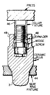
Figure d is a sectional elevational view
illustrating an expandable metal screw member portion
for wedging in a ceramic plug cavity;
Figure 2 is a partly sectional elevational
view illustrating a pre-wedging step for bending the
expandable metal section until it is fully bent;
Figure 3 is a partly sectional elevational
view illustrating the ceramic valve plug threadably
engaged onto a threaded valve stem for final wedging;
Figure 4 is an elevational view of an
elongated screw member which is wedged into the ceramic
plug cavity;
Figure 5 is a sectional view of a wedge
member mountable on the screw of Figure 4;
Figure 6 is a sectional view illustrating a
metal expansion member wedged into the ceramic cavity
in the steps of Figures 2 and 3; and
Figure 7 is a bottom plan view of the
expansion member of Figure 6.

2~8~~C~
-4- 21-56(10732)A
Detailed Description
The principles of the present invention will
be described in connection with the preferred
embodiment of the invention illustrated in Figures 1-7
wherein a valve plug/stem assembly 10 includes a valve
plug 12 foamed of ceramic material which is attached to
a radially operated or longitudinally operated valve
member, such as a metal valve stem 14. The drawings
illustrate a preferred technique for attaining a
reliable, inexpensive and readily constructed
attachment of ceramic valve plug 12 onto metal stem 14.
Ceramic plug 12 includes a cavity 16 for
receiving a wedging screw assembly 18 which forms the
means for attachment of the ceramic plug onto the valve
stem.
Wedging screw assembly 18 includes an
elongated screw member 20, a wedge ring 22, and an
expander ring 24 each of which components is mast
clearly identified in Figures 4-7. Screw member 20
includes a threaded section 26 at one end and a
shoulder 28 at the other end formed integral with the
screw and having a slightly larger diameter than the
threaded end. Base 30 extends from one end of the
screw as shown in Figure 4.
Wedge ring 22 includes a lower face 32 and an
upper face 34 with an angled wedging surface 36
therebetween. The inner ring diameter is sized so that
wedge ring 22 can be inserted over threaded section 26
until lower face 32 rests on shoulder 28.
Expander ring 24 is in the form of a split
ring having a base portion 38 from which there extends
several split leg sections 40 each of which is
separated by a small space 42. As shown in Figure 1,
the expander ring inner diameter is sized so as to be
inserted over threaded section 26 with split legs 40
resting on angled surface section 36 of the wedge ring.

2~5~~~~
-5- 21-56(10732)A
It is understood of course that the screw 20, wedge
ring 22 and expander ring 24 components of the wedging
screw assembly 18 are all formed of metal.
In accordance with the present invention,
wedging screw assembly 18 is securely wedged within
cavity 16 as threaded screw section 26 engages the
threaded section of stem 14. Figures 1 and 2
illustrate the preferred embodiment of the invention
wherein the screw assembly is initially pre-wedged into
the cavity so as to fully bend expander ring split legs
40 before the final wedging operation is attained in a
second step of tightening the plug/screw combination
onto metal stem 14 as shown in Figure 3.
Initially, the wedging screw assembly is put
together with wedge ring 22 assembled onto shoulder 28
and expander ring 24 resting on the wedge ring. Next,
the wedging screw assembly 18 is inserted into cavity
16 until base 30 rests on the cavity floor and so that
threaded section 26 extends beyond the upper end of
cavity 12. Screw base 30 and the bottom of cavity 16
are formed with matching locking surfaces so that screw
20 and plug 12 rotate together.
The screw assembly 18 and plug 12 are then
inserted into a fixture such as illustrated in Figure
1. In particular, plug 12 is inserted into a seat ring
fixture 44 and screw 20 is inserted into a collar
fixture 46 with the collar fixture extensions in
contact with base 38 of expander ring 24.
A pre-wedging operation is now initiated
wherein a load is applied to the collar fixture while
the seat ring fixture is supported in position. This
operation forces expander ring 24 onto wedge ring 22 to
fully bend split legs 40 outwardly along angled surface
36. As shown in Figure 2, sufficient loading is
supplied to the collar fixture so as to ensure that
split legs 40 are fully bent around wedge ring 22.

~O~~~Q1
-6- 21-56(10732)A
It has been found that with a constructed
prototype of the invention incorporating a ceramic
valve plug and stainless steel alloy S17400 Double
H1150 for the mating metal parts (screw, expander,
wedge) a load of about 1500 pounds is required to fully
bend the expander legs during the pre-wedging
operation.
Next, threaded section 26 is threadably
engaged onto stem 14 and the screw is tightened to
l0 ensure there is a uniform contact engagement of the
split legs 40 with the opposite ceramic surfaces within
cavity 16. In this connection, it has been found most
desirable to provide opposite flat surfaces 48 on the
exterior of ceramic plug 12 so that the ceramic plug
can be held in a vice 50 with metal plates 52. Stem 14
may then be tightened by using a torque wrench on stem
14 until the desired uniform contact of split legs 40
with the opposite ceramic surfaces in cavity 16 is
achieved.
In the same constructed prototype of the
invention described above, it has been found that the
screw should be torqued to about 8-9 foot-pounds to
achieve the desired uniform loading of this final
wedging step and to provide a preloading of the
plug/stem assembly greater than the expected applied
load experienced in service due to pressure unbalance
forces tending to loosen the plug/stem assembly. If
desired, one may drill and pin the ceramic plug
assembly to the metal stem as in a standard plug/stem
assembly.
The foregoing detailed description has been
given for clearness of understanding only, and no
unnecessary limitations should be understood therefrom,
as modifications will be obvious to those skilled in
the art.

Dessin représentatif
Une figure unique qui représente un dessin illustrant l'invention.
États administratifs

2024-08-01 : Dans le cadre de la transition vers les Brevets de nouvelle génération (BNG), la base de données sur les brevets canadiens (BDBC) contient désormais un Historique d'événement plus détaillé, qui reproduit le Journal des événements de notre nouvelle solution interne.

Veuillez noter que les événements débutant par « Inactive : » se réfèrent à des événements qui ne sont plus utilisés dans notre nouvelle solution interne.

Pour une meilleure compréhension de l'état de la demande ou brevet qui figure sur cette page, la rubrique Mise en garde , et les descriptions de Brevet , Historique d'événement , Taxes périodiques et Historique des paiements devraient être consultées.

Historique d'événement

Description Date
Inactive : Regroupement d'agents 2013-10-22
Inactive : CIB de MCD 2006-03-11
Le délai pour l'annulation est expiré 2005-10-14
Lettre envoyée 2004-10-14
Lettre envoyée 2003-09-15
Accordé par délivrance 2002-08-20
Inactive : Page couverture publiée 2002-08-19
Inactive : Taxe finale reçue 2002-06-03
Préoctroi 2002-06-03
Lettre envoyée 2002-01-23
Un avis d'acceptation est envoyé 2002-01-23
Inactive : Approuvée aux fins d'acceptation (AFA) 2002-01-15
Modification reçue - modification volontaire 1999-11-04
Lettre envoyée 1999-10-05
Inactive : Renseign. sur l'état - Complets dès date d'ent. journ. 1999-10-05
Inactive : Dem. traitée sur TS dès date d'ent. journal 1999-10-05
Exigences pour une requête d'examen - jugée conforme 1999-09-21
Toutes les exigences pour l'examen - jugée conforme 1999-09-21
Demande publiée (accessible au public) 1993-04-12

Historique d'abandonnement

Il n'y a pas d'historique d'abandonnement

Taxes périodiques

Le dernier paiement a été reçu le 2001-10-01

Avis : Si le paiement en totalité n'a pas été reçu au plus tard à la date indiquée, une taxe supplémentaire peut être imposée, soit une des taxes suivantes :

  • taxe de rétablissement ;
  • taxe pour paiement en souffrance ; ou
  • taxe additionnelle pour le renversement d'une péremption réputée.

Les taxes sur les brevets sont ajustées au 1er janvier de chaque année. Les montants ci-dessus sont les montants actuels s'ils sont reçus au plus tard le 31 décembre de l'année en cours.
Veuillez vous référer à la page web des taxes sur les brevets de l'OPIC pour voir tous les montants actuels des taxes.

Historique des taxes

Type de taxes Anniversaire Échéance Date payée
TM (demande, 5e anniv.) - générale 05 1997-10-14 1997-10-08
TM (demande, 6e anniv.) - générale 06 1998-10-14 1998-10-07
Requête d'examen - générale 1999-09-21
TM (demande, 7e anniv.) - générale 07 1999-10-14 1999-10-06
TM (demande, 8e anniv.) - générale 08 2000-10-16 2000-10-04
TM (demande, 9e anniv.) - générale 09 2001-10-15 2001-10-01
Taxe finale - générale 2002-06-03
TM (brevet, 10e anniv.) - générale 2002-10-14 2002-10-03
Enregistrement d'un document 2003-08-07
TM (brevet, 11e anniv.) - générale 2003-10-14 2003-09-17
Titulaires au dossier

Les titulaires actuels et antérieures au dossier sont affichés en ordre alphabétique.

Titulaires actuels au dossier
FISHER CONTROLS INTERNATIONAL LLC
Titulaires antérieures au dossier
MELVIN LEW OSGOOD
RODNEY PAUL WESTERN
Les propriétaires antérieurs qui ne figurent pas dans la liste des « Propriétaires au dossier » apparaîtront dans d'autres documents au dossier.
Documents

Pour visionner les fichiers sélectionnés, entrer le code reCAPTCHA :


Pour visualiser une image, cliquer sur un lien dans la colonne description du document. Pour télécharger l'image (les images), cliquer l'une ou plusieurs cases à cocher dans la première colonne et ensuite cliquer sur le bouton "Télécharger sélection en format PDF (archive Zip)" ou le bouton "Télécharger sélection (en un fichier PDF fusionné)".

Liste des documents de brevet publiés et non publiés sur la BDBC .

Si vous avez des difficultés à accéder au contenu, veuillez communiquer avec le Centre de services à la clientèle au 1-866-997-1936, ou envoyer un courriel au Centre de service à la clientèle de l'OPIC.


Description du
Document 
Date
(aaaa-mm-jj) 
Nombre de pages   Taille de l'image (Ko) 
Description 1993-12-03 6 244
Abrégé 1993-12-03 1 15
Revendications 1993-12-03 4 120
Dessins 1993-12-03 1 44
Dessin représentatif 1999-06-17 1 15
Dessin représentatif 2002-07-16 1 11
Rappel - requête d'examen 1999-06-14 1 118
Accusé de réception de la requête d'examen 1999-10-04 1 193
Avis du commissaire - Demande jugée acceptable 2002-01-22 1 164
Avis concernant la taxe de maintien 2004-12-08 1 173
Correspondance 2002-06-02 1 59
Taxes 1998-10-06 1 49
Taxes 2001-09-30 1 57
Taxes 2002-10-02 1 48
Taxes 1997-10-07 1 57
Taxes 1999-10-05 1 55
Taxes 2000-10-03 1 56
Taxes 1995-09-20 1 45
Taxes 1996-09-24 1 46
Taxes 1994-09-29 1 45