Sélection de la langue

Search

Sommaire du brevet 2080647 

Énoncé de désistement de responsabilité concernant l'information provenant de tiers

Une partie des informations de ce site Web a été fournie par des sources externes. Le gouvernement du Canada n'assume aucune responsabilité concernant la précision, l'actualité ou la fiabilité des informations fournies par les sources externes. Les utilisateurs qui désirent employer cette information devraient consulter directement la source des informations. Le contenu fourni par les sources externes n'est pas assujetti aux exigences sur les langues officielles, la protection des renseignements personnels et l'accessibilité.

Disponibilité de l'Abrégé et des Revendications

L'apparition de différences dans le texte et l'image des Revendications et de l'Abrégé dépend du moment auquel le document est publié. Les textes des Revendications et de l'Abrégé sont affichés :

  • lorsque la demande peut être examinée par le public;
  • lorsque le brevet est émis (délivrance).
(12) Brevet: (11) CA 2080647
(54) Titre français: DISTRIBUTEUR DE PAPIER HYGIENIQUE AVEC MECANISME DE VERROUILLAGE
(54) Titre anglais: TOILET TISSUE DISPENSER WITH LOCK
Statut: Périmé et au-delà du délai pour l’annulation
Données bibliographiques
(51) Classification internationale des brevets (CIB):
  • A47K 10/24 (2006.01)
  • A47K 10/32 (2006.01)
  • A47K 10/38 (2006.01)
(72) Inventeurs :
  • MERRIWEATHER, FRANK, JR. (Etats-Unis d'Amérique)
(73) Titulaires :
  • BOBRICK WASHROOM EQUIPMENT, INC.
(71) Demandeurs :
  • BOBRICK WASHROOM EQUIPMENT, INC. (Etats-Unis d'Amérique)
(74) Agent: MACRAE & CO.
(74) Co-agent:
(45) Délivré: 1995-07-18
(22) Date de dépôt: 1992-10-15
(41) Mise à la disponibilité du public: 1993-08-19
Requête d'examen: 1994-12-08
Licence disponible: S.O.
Cédé au domaine public: S.O.
(25) Langue des documents déposés: Anglais

Traité de coopération en matière de brevets (PCT): Non

(30) Données de priorité de la demande:
Numéro de la demande Pays / territoire Date
07/836,355 (Etats-Unis d'Amérique) 1992-02-18

Abrégés

Abrégé anglais


A toilet tissue dispenser having a frame with a central
arm and spaced side arms, and spindles for rolls of tissue, with
each of the spindles having opposed spindle pins for rotation in
the frame between the central arm and a side arm, opposed slots in
the central arm for slidingly receiving a spindle pin of each of
the spindles, a locking member carried in the central arm and
movable between a locked position blocking the slots and an
unlocked position not blocking the slots, and a lock mechanism
mounted in the central arm for actuating the locking member.

Revendications

Note : Les revendications sont présentées dans la langue officielle dans laquelle elles ont été soumises.


THE EMBODIMENTS OF THE INVENTION IN WHICH AN EXCLUSIVE PROPERTY
OR PRIVILEGE IS CLAIMED ARE DEFINED AS FOLLOWS:
1. In a toilet tissue dispenser having a frame with
sides and a spindle for a roll of tissue, said spindle having
opposed spindle pins for rotation in said frame sides, the
improvement including in combination:
slot means defining a slot in one of said sides for
slidingly receiving one of said spindle pins, said slot defining
a first plane;
a locking member carried in said one side and movable
between a locked position blocking said slot and an unlocked
position not blocking said slot; and
a lock mechanism mounted in said one side for rotating
said locking member in a plane perpendicular to said first plane,
said lock mechanism including a sleeve mounted in said one side
and a key operated tumbler rotatably carried in said sleeve, with
said locking member carried on said tumbler for rotation into and
out of said slot, said locking member including a plate having a
wing for moving into and out of said slot.
2. A dispenser as defined in claim 1 wherein said plate
has opposed wings and opposed arcuate sections between said
wings, with each of said arcuate sections having a first portion
of one radius and a second portion of a second different radius.
3. In a toilet tissue dispenser having a frame with
sides and a spindle for a roll of tissue, said spindle having
opposed spindle pins for rotation in said frame sides, the
improvement including in combination:
slot means defining a slot in one of said sides for
slidingly receiving one of said spindle pins, said slot defining
a first plane;
a locking member carried in said one side and movable
between a locked position blocking said slot and an unlocked
position not blocking said slot; and
-6-

a lock mechanism mounted in said one side for rotating
said locking member in a plane perpendicular to said first plane,
said lock mechanism including a sleeve mounted in said one side
and a key operated tumbler rotatably carried in said sleeve, with
said locking member carried on said tumbler for rotation into and
out of said slot, said locking member including a plate having a
wing for moving into and out of said slot;
said frame having a mounting surface and said one side
having an internal cavity open to said mounting surface providing
access to said lock tumbler from said mounting surface, and
said one side having an opening to said cavity for
slidingly receiving said lock sleeve, and
including attaching means positionable in said cavity
from said mounting surface and engageable with said lock tumbler
for retaining said lock in position in said one side.
4. In a toilet tissue dispenser having a frame with a
central arm and spaced side arms, and spindles for rolls of
tissue, with each of said spindles having opposed spindle pins
for rotation in said frame between said central arm and a side
arm,
the improvement including in combination:
slot means defining opposed slots in said central arm
for slidingly receiving a spindle pin of each of said spindles;
a locking member carried in said central arm and movable
between a locked position blocking said slots and an unlocked
position not blocking said slots; and
a lock mechanism mounted in said central arm for
actuating said locking member, said lock mechanism including a
sleeve mounted in said central arm and a key operated tumbler
rotatably carried in said sleeve, with said locking member
carried on said tumbler for rotation into and out of said slots,
said locking member including a plate having opposed wings for
moving into and out of said slots.
5. A dispenser as defined in claim 4 wherein said plate
- 7 -

has opposed arcuate sections between said wings, with each of
said arcuate sections having a first portion of one radius and a
second portion of a second different radius.
6. In a toilet tissue dispenser having a frame with a
central arm and spaced side arms, and spindles for rolls of
tissue, with each of said spindles having opposed spindle pins
for rotation in said frame between said central arm and a side
arm,
the improvement including in combination:
slot means defining opposed slots in said central arm
for slidingly receiving a spindle pin of each of said spindles;
a locking member carried in said central arm and movable
between a locked position blocking said slots and an unlocked
position not blocking said slots; and
a lock mechanism mounted in said central arm for
actuating said locking member;
said frame having a mounting surface and said central
arm having an internal cavity open to said mounting surface
providing access to a lock tumbler from said mounting surface,
and
said central arm having an opening to said cavity for
slidingly receiving a lock sleeve, and
including attaching means positionable in said cavity
from said mounting surface and engageable with said lock tumbler
for retaining said lock mechanism in position in said central
arm.
- 8 -

Description

Note : Les descriptions sont présentées dans la langue officielle dans laquelle elles ont été soumises.

20806g~7
~ ;~
- TOILET TISSUE DISPEN~ER WITH LOCK
BACKGROUND OF ~HE INVENTION
This -invention relates to toilet tissue dispensers and
in particular, to a new and improved toilet tissue dispenser with
a spindle for the roll of tissue and with a lock for retaining the
spindle in the frame of the dispenser.
Problems with theft of rolls of tissue and with
vandalism arise in many installations of tissue dispensers and it
is an object of the present invention to provide a simple and
inexpensive yet effective lock for retaining spindles in
dispensers.
Various forms of roll tissue dispensers are shown in the
1991 catalog of applicant's assignee Bobrick Washroom Equipment,
Inc. at pages 32 and 33. Some of these models have a pivoted
cover plate with lock.
There are prior patents showing dispensers with locks in
other locations. U.S. Patents to Agamaite 2,510,537 and to Wyant
4,807,823 show a lock which enqages the inside of a hollow
spindle. U.S. Patent to Goetz 4,690,343 shows a paper holder with
pivoted rods positioned inside the spindle and controlled by a
lock.
It is a particular object of the invention to provide a
new and improved .issue dispenser with locking arrangement which
can be utilized with a single roll dispenser and with a dual roll
dispenser. An addit~onal object of the invention is to provide
such a dis~enser which can utilize a conventional lock and key
with the lock sleeve mounted in the frame and with the spindle
locking member carried on the lock tumbler. An additional object
is to provide such a construction wherein access to the lock and
locking member is concealed within the frame of the dispenser.
- 1 - ~

2080647
._
Other objects, advantages, features and results will
more fully appear in the course of the following description.
~UNNARY OF THB INVBNTION
Generally speaking, these objects are met by the present
invention which provides in a toilet tissue dispenser having a
frame with sides and a spindle for a roll of tissue, the spindle
having opposed spindle pins for rotation in the frame sides, the
improvement including in combination: slot means defining a slot
in one of the sides for slidingly receiving one of the spindle
pins, the slot defining a first plane; a locking member carried
in the one side and movable between a locked position blocking
the slot and an unlocked position not blocking the slot; and a
lock mechAnism mounted in the one side for rotating the locking
member in a plane perpendicular to the first plane, the lock
mech~;sm including a sleeve mounted in the one side and a key
operated tumbler rotatably carried in the sleeve, with the
locking member carried on the tumbler for rotation into and out
of the slot, the locking member including a plate having a wing
for moving into and out of the slot.
BRIBF nB~CPTPTION OF T~B DRa~ING~
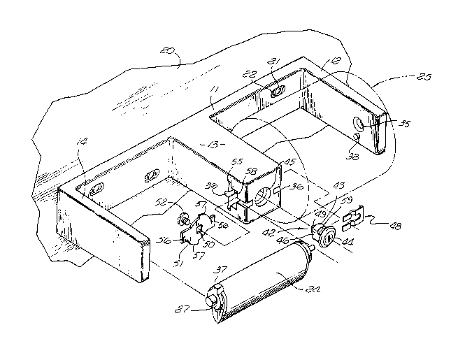
Fig. 1 is a perspective view of a dual toilet tissue
dispenser showing the dispenser mounted on a wall with one roll
of tissue in phantom lines and incorporating the presently
preferred embodiment of the invention; and
Fig. 2 is a top view of the dispenser of Fig. 1, shown
partly in section.
~'

2~06~7
... ~ `. .
DESCRIPTION OF THE PREFER~ED EMBODIME~T
The dispenser includes a housing or frame 11 with sides
in the form of arms 12,13,14. The frame 11 has a mounting surface
16 and typically is a metal casting with cavities 17,18,19 in the
arms 12,13,14, respec ively. The frame may be mounted on a wall
20 by screws 21~in mounting slots 22.
Spindles 24 are carried in the frame between spaced arms
for supporting rolls 25 of toilet tissue. In the embodiment
illustrated, the spindles have the features of U.S. patent
3,871,593. Of course other spindle constructions can be utilized
if desired.
Each spindle 24 includes a tube 26 with end caps 27,28.
Typically the tube is of metal and the end caps are molded of a
suitable plastic. A pin 29 is molded as a portion of the cap 27.
Another pin 30 is formed as a U-shaped rod carried in the cap 28,
with a spring 31 incorporated for urging the pin 30 outward from
the cap 28. Pins, with or without springs, can be used at each
end of the spindle if desired and alternatively, integrally molded
pins can be used in the caps if desired.
In the embodiment illustrated, the pin 29 of a spindle
rotates in an opening 35 in a side arm, and the pin 30 slides into
and rotates in a slot 36 in the central arm. A boss 37 molded as
a portion of the spindle end cap 27 is positioned to engage a pin
38 projecting inward from the side arm to achieve the controlled
delivery feature.
A lock mechanism 42 is carried in the arm 13, with the
lock having a sleeve 43 and a key operated tumbler 44 rotating in
the sleeve. The lock is positioned in an opening 45 in the arm
13, preferably with flats 46 on the sleeve mating with flats 47 in
the opening 45 for preventing rotation of the sleeve. The lock is
retained by a spring clip 48 which slides laterally in an opening
S8 in the arm 13. The clip 48 is U-shaped and rides in grooves 59
in the lock sleeve 43.

~08~16~7
,~ ;
A square boss 49 on the inner end of the tumbler 44
engages a mating opening 50 in a locking member 51, with the
locking member preferably being a plate which is held in position
on the tumbler by a screw 52. The plate 51 is positioned in a
slot 55 in the arm 13. In assembling the locking arrangement, the
plate 51 is inserted- laterally in the slot 55, the lock 42 is
inserted through the opening 45 with the boss 49 entering the
opening 50, and the screw 52 is inserted from the mounting surface
through the cavity 18. The screw is tightened into the tumbler so
that the plate 51 rotates with the tumbler when the appropriate
key is utilized. In the embodiment illustrated, the slots 36 and
lock mechani-sm 42 are horizontally disposed, but couId be
vertically arranged if desired.
In the preferred embodiment, the plate 51 has opposed
wings 56 and opposed arcuate sections 57, with each arcuate
section having a first portion of one radius and a second portion
of a second greater radius, as best seen in Fig. 1.
The dispenser is shown in the normal locked position in
Fig. 2 with the wings 56 of the locking member 51 closing the
slots 36 so that the spindle pins in the slots 36 cannot be moved
forward. In order to remove a spindle, the tumbler 44 is operated
by a key to rotate the tumbler 90 and move the wings 56 to an
unlocked position not blocking the slots 36. This permits pulling
the spindle forward to move the pin 31 out of the slot 36 and
thereby remove the spindle from the frame. After a roll of tissue
is positioned on the spindle, the spindle with roll is inserted
into the frame to the position of Fig. 2, and the lock tumbler is
rotated to the locked position returning the wings 56 of the
locking member to the locked position of Fig. 2.
With this configuration, the lock itself is held in
place by the screw 52 which is concealed within the frame and can
only be accessed by removing the frame from the wall. Also, the
spindle cannot be removed from the frame without actuating the
lock to move t~e locking member from the slot blocking condition
to the not blocking condition.
-- 4

2~647 -- -
.
While a dual dispenser has been illustrated and
described, the construction with the locking feature can also be
utilized in a frame or housing for a single roll of tissue. Also
the constructior. can be usecl in a hooded roll tissue dispenser,
single or double.

Dessin représentatif
Une figure unique qui représente un dessin illustrant l'invention.
États administratifs

2024-08-01 : Dans le cadre de la transition vers les Brevets de nouvelle génération (BNG), la base de données sur les brevets canadiens (BDBC) contient désormais un Historique d'événement plus détaillé, qui reproduit le Journal des événements de notre nouvelle solution interne.

Veuillez noter que les événements débutant par « Inactive : » se réfèrent à des événements qui ne sont plus utilisés dans notre nouvelle solution interne.

Pour une meilleure compréhension de l'état de la demande ou brevet qui figure sur cette page, la rubrique Mise en garde , et les descriptions de Brevet , Historique d'événement , Taxes périodiques et Historique des paiements devraient être consultées.

Historique d'événement

Description Date
Inactive : CIB de MCD 2006-03-11
Le délai pour l'annulation est expiré 2003-10-15
Lettre envoyée 2002-10-15
Inactive : TME en retard traitée 2001-10-18
Inactive : TME en retard traitée 2000-10-19
Accordé par délivrance 1995-07-18
Exigences pour une requête d'examen - jugée conforme 1994-12-08
Toutes les exigences pour l'examen - jugée conforme 1994-12-08
Demande publiée (accessible au public) 1993-08-19

Historique d'abandonnement

Il n'y a pas d'historique d'abandonnement

Historique des taxes

Type de taxes Anniversaire Échéance Date payée
TM (brevet, 5e anniv.) - générale 1997-10-15 1997-10-14
TM (brevet, 6e anniv.) - générale 1998-10-15 1998-10-13
TM (brevet, 7e anniv.) - générale 1999-10-15 1999-10-04
Annulation de la péremption réputée 2001-10-15 2000-10-19
TM (brevet, 8e anniv.) - générale 2000-10-16 2000-10-19
TM (brevet, 9e anniv.) - générale 2001-10-15 2001-10-18
Annulation de la péremption réputée 2001-10-15 2001-10-18
Titulaires au dossier

Les titulaires actuels et antérieures au dossier sont affichés en ordre alphabétique.

Titulaires actuels au dossier
BOBRICK WASHROOM EQUIPMENT, INC.
Titulaires antérieures au dossier
FRANK, JR. MERRIWEATHER
Les propriétaires antérieurs qui ne figurent pas dans la liste des « Propriétaires au dossier » apparaîtront dans d'autres documents au dossier.
Documents

Pour visionner les fichiers sélectionnés, entrer le code reCAPTCHA :


Pour visualiser une image, cliquer sur un lien dans la colonne description du document. Pour télécharger l'image (les images), cliquer l'une ou plusieurs cases à cocher dans la première colonne et ensuite cliquer sur le bouton "Télécharger sélection en format PDF (archive Zip)" ou le bouton "Télécharger sélection (en un fichier PDF fusionné)".

Liste des documents de brevet publiés et non publiés sur la BDBC .

Si vous avez des difficultés à accéder au contenu, veuillez communiquer avec le Centre de services à la clientèle au 1-866-997-1936, ou envoyer un courriel au Centre de service à la clientèle de l'OPIC.


Description du
Document 
Date
(aaaa-mm-jj) 
Nombre de pages   Taille de l'image (Ko) 
Abrégé 1995-07-18 1 18
Page couverture 1995-07-18 1 15
Description 1995-07-18 5 184
Revendications 1995-07-18 3 133
Dessins 1995-07-18 2 56
Abrégé 1995-07-18 1 18
Dessin représentatif 1998-10-14 1 34
Quittance d'un paiement en retard 2000-10-27 1 171
Quittance d'un paiement en retard 2001-10-26 1 171
Avis concernant la taxe de maintien 2002-11-12 1 175
Taxes 1996-09-27 1 50
Taxes 1995-09-29 1 64
Taxes 1994-09-29 1 73
Correspondance de la poursuite 1994-12-07 2 51
Correspondance reliée au PCT 1995-05-05 1 36
Correspondance reliée au PCT 1995-06-21 1 46
Courtoisie - Lettre du bureau 1995-01-20 1 61
Correspondance reliée au PCT 1994-12-08 1 36
Correspondance de la poursuite 1994-12-07 1 35