Note : Les descriptions sont présentées dans la langue officielle dans laquelle elles ont été soumises.
2 0 8 1 8 7 ~!
TITLE
WINDOW BLIND ACTIVATOR
BACKGROUNDQF TH E I NVENT I ON
1. Fie_d of the Invention
This invention relates generally to the field of window
blinds and more particularly to means of raising and lowering
collapsible blind fabrics.
2. Description of the Prior Art
Many window blind assemblies employ collapsible blind
fabric which extends from a headrail mounted adjacent a window or
door. These collapsible fabric window blind assemblies are
operated by raising or lowering the blind fabric. The term
"blind fabric" refers to material used as a covering in venetian
blinds, roman blinds, honeycomb blinds and pleated blinds.
It is known to raise and lower the blind fabric by
intermittently passing a cord through the blind fabric and
connecting the cord to the blind fabric at some point. This cord
typically enters the headrail, passes over a roller located in
the headrail, and then exits the headrail, hanging down alongside
the blind fabric. When the cord is pulled downward, the blind
fabric is drawn upward. As the cord is allowed to move up, the
weight of the blind fabric causes the blind fabric to move down.
2881~r~ i
This ~3eneral concept is usually known to employ more than on~
cord.
Devices ~sed to activate the cord upward or downward al-e
known that incorporate a hollow take-up tube dispose~ around and
threadably engaged to a stationary threaded guide. In such
devices, a cord is connected at its one end to the take-up tube
and at its other end to the blind fabric. The take-up tube is
then activated to manually rotate to wind or unwind the cord.
Such a device is generally known as a tube cord lift system.
It is also known to staple the uppermost portion of the
blind fabric to a long, rectangular strip. This s~rip is then
slid into a groove along the bottom of the headrail and the blind
fabric is thus attached to the headrail.
When raising or lowering the blind, it is desirable for
the blind fabric to remain in the position it has been placed.
For this reason, various clutch means have been employed in the
art. A common clutch means is a bi-directional clutch. Some
examples of this type of clutch are shown in U.S. Patent No.
4,372,432 and U.S. Patent No. 4,433,76S. A typical bi-
directional clutch employs two generally cylindrical elements,
one being a drive element and the other being a driven element.
The elements are designed with a transmission and locking means,
typically one or more springs, cooperating with them s~ that when
a torque is applied to the drive element in either direction, the
drive element is rotated which turns the driven element as well.
However, a torque applied directly to the driven element will
208187t~
resul~: in the driven element being locked in position. This
locking means is generally effective, however, the springs
utili.zed in the above system generally make a complete rotation
for each rotation of the cylindrical element. Thus, as the
spring rotates, a repetitive noise, called chatter, is produced.
Furthermore, as the cylindrical elements are rotated, the spring
is continually engaging and disengaging thus producing a
vibration in the cords and the shade. It also creates a
resistance that increases the actual load to the operator.
A bi-directional limit torque slip element as disclosed
in U.S. Patent No. 3,450,365 to Kaplan employs a spring having a
varying diameter. Such a slip element mechanism would be
particularly useful in a window blind system due to the desire to
have different pre-torques acting in opposite directions and
would reduce many of the shortcomings in the above-mentioned pre-
torque means.
SUMMARY OF THE INVENTION
The present invention provides a device for raising and
lowering pleated window blinds. The present device is a tube
cord lift system that employs a bi-directional, ~riction brake in
cooperation with a drive core which enables a greater pre-torque
in one rotational direction than the opposite rotational
direction. The present invention thus transmits torque directly
through a drive core and not through a clutch. Furthermore, the
present invention utilizes a pre-torque means that is quieter
8 7 ~
than the clutch devices previously utilized in the art. This is
due to the varying-diameter spring ut:ilized in the friction brake
not having to rotate with every rotation of the drive core and to
the more continual disengagement of the varying-diameter spring
durin~ rotation. The preferred means of rotating the take-up
tube is an endless pull cord cooperating with the drive core.
Another means of rotating the take-up tube is the drive core
cooperating with an elongated pull cord or a wand operated worm
gear. Stops are provided to prevent the take-up tube from
travelling more than a predetermined amount in a longitudinal
direction. Preferably endplugs or collars attached to the tube
are used as stops. Other details, objects and advan~ages of the
invention will become apparent as the following description of
certain present preferred embodiments thereof proceeds.
BRIEF DESCRIPTION OF T~E DRAWINGS
Figure 1 is a front view partially cut away of the
present preferred embodiment.
Figure 2 is a side view of the preferred headrail.
Figure 3 is a side view of the endplug.
Figure 4 is a side view of the threaded insert.
Figure 5 is a front view of a cradle.
Figure 6 is an exploded view of the drive core and
friction brake of the preferred embodiment.
Figure 7 is a front view of the tube clip.
Figure 8 is a side view of the offset profile.
Figure 9 is a front view of the dual stop.
--4--
2~8 ~ ~7~
DESCRIPTION OF THE PREFERRED EMBODIMENTS
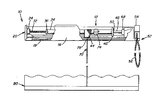
Referring first to Figure 1, system lo has an elongated
headrail 12. The preferred design of headrail 12, a side view of
which is shown in Figure 2, is as follows. A bottom face 14 that
is generally parallel to the ground extends longitudinally
adjacent to the upper portion of a window or door. A front face
16 extends upward perpendicularly from the front longitudinal
edge of bottom face 14. Front face 16 has a portion 15 that
extends parallel to bottom face 14. A rear face 18 extends
upward perpendicularly from the rear longitudinal edge of bottom
face 14. Rear face 18 has a portion 17 that extends parallel to
bottom face 14. Front face 16 is parallel to rear face 18.
Thus, the preferred headrail 12 is generally U-shaped. Headrail
12 is also preferably open-ended.
Where front face 16 meets bottom face 14, front face 16
extends downward approximately an eighth of an inch past the
front longitudinal edge of bottom face 14. Front face 16 then
curves approximately an eighth of an inch back towards rear face
18 creating one side of a longitudinal groove 19. similarly,
where rear face 18 meets bottom face 14, the other side of
longitudinal groove 19 is formed. Grooves 19 are loca~ed
directly opposite one another. Groove 19 is thus bordered on one
side by bottom face 14 and front face 16 and at the other side by
bottom face 14 and rear face 18.
2081~7~
Disposed at one end of headrail 12 is end plug 20. End
plug 20, shown in ~igure 3, has a backing portion 22 which is
generally square and abuts the end of headrail 12 thereby
enclosing that end. End plug 20 further has an extending portion
24 which extends perpendicularly from backing portion 22 and
extends longitudinally within U-shaped headrail 12. Extending
portion 24 of end plug 20 has a cylindrical hole 26 bored
longitudinally into it at .its center. Thus, extending portion 24
has an annular surface 28 facing away from backing portion 22. A
portion of endplug annular surface 28 that extends radially from
cylindrical hole 26 is raised to form a ledge 30. A threaded
guide 32 is fixed within cylindrical hole 26. Threaded guide 32
extends away from backiny portion 22 of endplug 20 extending
longitudinally within U-shaped headrail 12. Threaded guide 32 is
a cylindrical section of threaded material.
A hollow, cylindrical take-up tube 34 is placed around
threaded guide 32. Take-up tube 34 has a threaded insert 36
fixed at its one end. Shown in Figure 4, threaded insert 36 has
a threaded hole 38 through îts center, through which threaded
guide 32 i5 disposed. As threaded insert 36 rotates relative to
threaded guide 32, threaded insert 36 carries take-up tube 34
longitudinally along threaded guide 32. Threaded insert 36 has
an annular surface 40 facing toward endplug 20. The outside
diameter of annular surface 40 is greater than the outside
diameter of take-up tube 34. Threaded insert annular surface 40
has a raised ledge 42 extending radially from threaded hole 38.
--6--
2081~7~
Take-up tube 34 is rotatably secured wi~l~in headrail
preferably by at least two cradles 44. Cradles 44, shown in
Figure 5, have a base portion 47 and an extending portion 49.
Cradles 44 are secured to headrail 12 by any convenien~ means,
however, the preferred means is by fitting base portion 47 within
the area bordered by front face 16 and front face portion l5 on
one side and rear face 18 and rear face portion 17 on the other
side. Also, cradles 44 have a port 43 extending from base
portion 47. The cradle posts 43 are then fitted through a hole
in bottom face 14 of headrail 12.
As take-up tube 34 is rotated, threaded inset 36 travels
along the thread of threaded guide 32. As threaded insert 36
travels along the length of threaded guide 32, take-up tube 34 is
carried longitudinally along threaded guide 32. When threaded
insert 36 travels longitudinally to where it reaches endplug 20,
threaded insert ledge 42 will engage endplug ledge 30. Once
threaded insert ledge 42 contacts endplug ledge 30, take-up tube
34 will not be able to rotate further in that direction or travel
longitudinally further in that direction.
Take-up tube 34 has a tube plug 46 fixed at its end
opposite to threaded insert 36. A drive shaft 48 extends throuc~h
a hole 50 on tube plug 46 and extends into take-up tube 34.
Drive shaft 48 has preferably a square cross section as does hole
50 through tube plug 46. Hole 50 is sized so as to engage drive
shaft 48, thus as drive shaft 48 is rotated, take-up tube 34 is
rotated. And as take-up tube 34 is rotated, tube 34 travels
2~31~7~
longitudinally about threa~e~ guide 32. The engagement of drive
shaft 48 with tube plug 46 through plug hole 50 allows a
rotational force to be transmitted from drive shaft 48 to tube
plug 46 while allowing take-up tube 34 to move longitudinally
relative to drive shaft 48.
Drive shaft 48 is fixed to drive means 52. The
preferred drive means is a bi-directional friction brake 5~
cooperating wi~h a drive core 58 engaged with an endless pull
cord 56. Drive means 52 shown in Figure 6, has a generall~
cylindrical brake core 58, a varying-diameter spring 60, a brake
cover 62 and a brake housing 64 that has a generall~ cylindrical
inner surface. Vrive core 58 is rotatably enclosed within brake
housing 64 and brake cover 62. Varying-diameter spring 60 is
located between drive core 58 and brake housing 64. Varying-
diameter spring 60 is designed to provide a pre-torque on drive
core 58 in both the clockwise and counterclockwise directions.
Drive core 58 has protrusions 66 within which endless pull cord
56 is disposed. Protrusions 66 are spaced a selected amount
apart so that endless pull cord 56 fits snugly within some of
protrusions 66. The rest of endless pull cord 56 extends down
from the clutch 54. Thus, frictional forces acting between pull
cord 56 and protrusions 6G cause a force ~pplied t;o pull cord 56
in a chosen direction to be transmitted to drive core 58. This
force transmitted to drive core 58 creates a torque acting upon
drive core 58 causing drive core 58 to rotate in the direction of
the force on pull cord 56. Drive shaft 48 is fixed to drive core
2081~
58 by cotter pin 68, therefore, as drive core 58 rotates, drive
shaft 48 rotates as well. ~3rake ~lOusillg 6~ has a hole 70 plac~
on it. Drive shaft 48 extends from drive core S8 through brake
housing hole 70 is supported by and engages with tube plug ~6.
Brake cover 62 and brake housing 64 are joined together
by any convenient means such as gluing or rivots, but the
preferred means is by screws. Brake housing 64 has several
generally cylindrical screw housings 65 extending toward brake
cover 62. Brake cover 62 has several screw holes 67 located so
that each screw housing 65 has a corresponding screw hole 67
adjacent to it when brake cover 62 is in position against brake
housing 64. Screws (not shown) are then placed through screw
holes 67 and are tightened into screw housing 65. Any number of
screws with corresponding screw holes 67 and screw housing 65 can
be used, however, it is preferred that two be located beneath and
at each side of protrusions 66. When the screw holes 67 and
screw housings 65 are located thus, the screws and screw housings
65 act as additional supports and guides for endless pull cord
56. Brake cover 62 is then secured at the end of headrail 12
opposite to the end having end plug 20.
One end of an elongated blind cord 72 is connected to
take-up tube 34. A tube clip 7~, shown bes~ in Fi~ure 7, ha9 a
generally semi-circular cross section and has a channel 76. Tuh~
~lip 72 is sized to fit snugly around take ~p tube 3~. Blind
cord 72 is placed through channel 76 and an end of that portion
of blind cord 72 is knotted. The knot on the end of blind cord
7 1~
72 is larger than the space created between channel 76 and take-
up tube 3~ so that the knot on blind cord 72 can not be pulled
through channel 76. An opening 78 is made on headrail 12 through
which blind cord 72 passes. The end of blind cord 72 is secured
to the bottom of a collapsible section of blind fabric 80. slind
cord 72 need not travel directly from frame opening 78 downward
to the bottom of blind fabric 80. Rather, blind cord 72 can
travel from frame opening 78, longitudinally along groove ls and
then downward to the bottom of blind fabric 80. An offset
profile 84 is placed within grooves 19. Offset profile 84, shown
in Figure 8, is designed so that when offset profile 84 is placed
within grooves 19 and an edge of blind fabric 80 is then inserted
into groove 19, the offset profile 84 and blind fabric 80 are
held securely within groove 19. Offset profile 84 is designed so
that one longitudinal edge of offset profile 84 is angled. This
angled edge 86 facilitates the entry of fabric 80 into groove 19.
In operation, the side of endless pull cord 56 is pulled
on the left of bi-directional friction brake 54 which applies a
counter-clockwise torque on clutch core 58. When this manually
applied torque overcomes the initial torque of varying-diameter
spring 60, drive core 58 rotates, which rotates drive shaft 48 in
the counter-clockwise direction. Drive sllaf~ 3 then engages
with tube plug 46 to rotate take-up tube 34. As take-up tube 34
rotates, blind cord 72 is wound around take-up tube 34 causing
the end of blind cord 72 attached to blind fabric 80 to be drawn
toward headrail 12. Once, blind fabric ~30 is drawn towards
--10--
2 ~ 81~
headrail 12, the weight of blind fabric ~0 actillg upon blind cord
72 creates a torque o~ take-up tube 3~ that would tend to cause
bllnd cord 72 to rotate take-up tube 34 in the clockwise
direction, thus allowing blind fabric 80 to drop away from
headrail 12. The initial torque supplied by spring 60 in the
clockwise direction is larger than the torque created by the
weight of fabric 80, thus blind fabric 80 is held in position
until a manual torque that overcomes the initial torque is
delivered at clutch 54 through endless pull cord 56. To lower
blind fabric 80, endless pull cord 56 is pulled on the right of
bi-directional friction brake 54, which applies a clockwise
torque on drive core 58. When this manually applied torque
exceeds the initial torque of varying-diameter spring 60 in the
counter-clockwise direction, drive core s8 rotates, which rotates
drive shaft 48 in the clockwise direction. Take-up tube 34 is
then rotated allowing blind cord 72 to unwind from take-up cord
72 is unwound, blind fabric 80 is lowered.
Varying-diameter spring 60 has a first section of coils
61 adjacent to a second section of coils 63. The spring 60 is
placed around drive core 58 and within clutch housing 64 so that
drive core 58, brake housing 64 and varying diameter spring 60
share a common longitudinal axis. First section of coils 61 has
a diameter that i5 approximately equal to the diameter of drive
core 58. Second section of coils 63 has a diameter that is
approximately equal to the diameter of brake housing 64. When
drive core 58 is rotated in the clockwise direction, the coils of
2~ 1 87~i
first coil section 61 will grip drive core 58 and further cause
the coils of second coil section 63 to retract away from the
cylindrical inner surface of brake housing 64. This allows
easier- rotation of drive core 58 rela~ive to brake housing 6~.
And, when drive core s~ is rotated in the counter-clockwise
direction, the coils of second coil section 63 will expand ou~
against the cylindrical surface of brake housing 64 and the coils
of first coil section 61 will expand out away from drive core 5B.
This allows easier rotation of drive core 58 relative to brake
housing 64. When the blind fabric ~0 is in the raised position,
the weight of blind fabric 80 creates a torque in the clockwise
direction. Thus, the initial torque provided by varying-diameter
spring 60 acting in the counter-clockwise direction is designed
to exceed the torque created by the weight of blind fabric 80.
Conversely, when the blind fabric 80 is manually raised, the
torque created by the weight of blind fabric 80 must be overcome.
For this reason, the pre-torque created by varying-diameter
spring 60 in the clockwise direction is designed to be minimal.
A routing hole 69 extends through brake cover 62 and
brake housing 64. Routing hole 69 allows a blind cord 72 to be
routed from the interior of headrail 12 to the exterior of
headrail 12 on either side of bottom faco 1~. Thus, a blil~d cold
72 could run from a take-up tube 34 directly through routing hole
69 above bottom face 14. Alternatively, routing hole 69 could be
situated below bottom face 14 and the blind cord 72 would then
run below bottom face 14 and then out through routing hole 69.
-12-
.
2 ~ 7 ~
P~eferably, take-up tube 34 is seamless. A seamless
tube offers the advantage of a smoo~her surface which makes the
winding and unwinding of blind cord 72 easier. Also, a seamless
tube which has been anodized will not discolor blind cord 72.
~ dditionally, multiple take-up tubes 34 co~lld be
threadably mated ~o threaded guide 32. The preferred variation
of this embodiment employs two take-up tubes 34. In this
embodiment, each take-up tube 34 has a threaded insert 36 and its
own drive means. Between each pair of take-up tubes 34 is a
dual-stop 35, shown in Fiyure 9, disposed around threaded guide
32. Dual-stop 35 has two surfaces 37 that face in opposite
directions to one another, one surface facing each ta.ke-up tube
34. Each dual-stop surface 37 has a ledge 39 as does each
threaded insert 36. As a take-up tube 34 reached dual-stop 35,
an insert ledge on threaded insert 36 will contact a dual-stop
surface ledge 3~ and prevent take-up tube 34 from moving further
in that direction.
Variations of the preferred embodiment could be made.
For example, headrail 12 need not be U-shaped. Headrail 12 could
be a long rectangular face with the cradles and clutch secured
thereto. Also, headrail 12 need not be open ended. Headrail 12
could instead have one or both ends be sided. In tlliS
embodiment, threaded guide 32 could be fixed directly to the
frame end. Similarly, clutch cover 62 could be fixed directly to
the opposite frame end.
2 0 ~
Also, although two cradles 44 are disclose~ in the
pr~ferred embodiment, any number of cradles 44 may be used to
support take-up tube 34. ~nd although cradles 44 are disclosed
as fixed to bottom face 1~, they could be fixed to front face 16,
rear face 18 or any combination of faces. In fact, any
convenient means of rotatably securing take-up tube 34 may be
employed instead of cradles 44.
The preferred means of rotating drive core 54 is an
endless pull cord 56 engaged to protrusions 66 of drive core 58.
However, any means can be used to rotate drive clutch 54 such as
engaging clutch 54 with an elongated pull cord.
Also, the preferred means of connecting blind cord 72 to
take-up tube 34 is by tube clip 74. However, any convenient
means can be used such as gluing, taping or passing cord 72
through a hole in take-up tube 34 and knotting the end of cord
72.
Both the extending portion 24 of endplug 20 and threaded
insert 36 are described in the preferred embodiment as having an
annular outer surface, however, these surfaces can have any
configuration.
While present preferred embodiments of the invention
have been shown, it is distinctly understood that ~hc invcntion
is not limited thereto but may be otherwise variously embodied
within the scope of the following claims.