Sélection de la langue

Search

Sommaire du brevet 2082192 

Énoncé de désistement de responsabilité concernant l'information provenant de tiers

Une partie des informations de ce site Web a été fournie par des sources externes. Le gouvernement du Canada n'assume aucune responsabilité concernant la précision, l'actualité ou la fiabilité des informations fournies par les sources externes. Les utilisateurs qui désirent employer cette information devraient consulter directement la source des informations. Le contenu fourni par les sources externes n'est pas assujetti aux exigences sur les langues officielles, la protection des renseignements personnels et l'accessibilité.

Disponibilité de l'Abrégé et des Revendications

L'apparition de différences dans le texte et l'image des Revendications et de l'Abrégé dépend du moment auquel le document est publié. Les textes des Revendications et de l'Abrégé sont affichés :

  • lorsque la demande peut être examinée par le public;
  • lorsque le brevet est émis (délivrance).
(12) Demande de brevet: (11) CA 2082192
(54) Titre français: INSTRUMENT DE DESSIN
(54) Titre anglais: DRAWING INSTRUMENT
Statut: Réputée abandonnée et au-delà du délai pour le rétablissement - en attente de la réponse à l’avis de communication rejetée
Données bibliographiques
Abrégés

Abrégé anglais


TITLE: DRAWING INSTRUMENT
ABSTRACT OF THE DISCLOSURE
A drawing instrument including two rulers each
having a head portion, a circular protrusion formed on
one of the head portions, and a circular recess formed
in the other head portion for slidable engagement with
the circular protrusion, the rulers are guided to
rotate relative to each other by the slidable
engagement between the circular protrusion and the
circular recess.

Revendications

Note : Les revendications sont présentées dans la langue officielle dans laquelle elles ont été soumises.


THE EMBODIMENTS OF THE INVENTION IN WHICH AN EXCLUSIVE
PROPERTY OR PRIVILEGE IS CLAIMED ARE DEFINED AS FOLLOWS:
I CLAIM:
1. A drawing instrument comprising a first ruler
including a first head portion formed on one end
thereof, a second ruler including a second head portion
formed on one end thereof, said first head portion
including a circular protrusion formed thereon, said
second head portion including a circular recess formed
therein for slidable engagement with said circular
protrusion of said first head portion, said first head
portion and said second head portion forming a circle
when said first head portion and said second head
portion are slidably engaged with each other, said
first head portion and said second head portion each
occupying at least three quarters of said circle,
whereby, said first ruler is rotatable relative to said
second ruler by said slidable engagement between said
circular protrusion and said circular recess, in order
to draft an angle by said first ruler and said ruler.
2. A drawing instrument according to claim 1,
wherein said first head portion includes a center
having a first hole formed therein, said second head
portion includes a center having a second hole formed
therein and aligned with said first hole of said first
head portion, whereby, the user may see through said
holes in order to align said centers of said head
portions with a center point.
3. A drawing instrument according to claim 1,
wherein said first head portion of said first ruler

includes an angular graduation formed thereon, said
second head portion of said second ruler includes a
convex lens formed thereon for enlarging said angular
graduation of said first head portion, and said second
head portion of said second ruler includes a pointer
formed thereon for indicating said angular graduation
of said first head portion.
4. A drawing instrument according to claim 1,
wherein said first head portion of said first ruler
includes a pin element engaged therein, said second
head portion of said second ruler includes an arcuate
slot formed therein, said pin element of said first
head portion is slidably engaged in said arcuate slot
of said second head portion, so that said second head
portion is further guided to rotate relative to said
first head portion.
5. A drawing instrument according to claim 4,
wherein said pin element includes a bolt and a nut for
slidably coupling said head portions together.

Description

Note : Les descriptions sont présentées dans la langue officielle dans laquelle elles ont été soumises.

2 ~ 9 2
5~ITLE: DRAWING INSTRUIIENT
2 The invention relates to a drawing instrument, and
3 more particularly to a drawing instrument suitable for
4 drafting angular ]ines.
A typical drawing instrument is disclosed in U.S.
6 Patent No. 5,020,233 and comprises two similar members
7 pivotally coupled together, this drawing instrument is
8 suitable for drafting right angle only.
9 The invention has arisen to mitigate and/or
obviate the afore-described disadvantages of the
11 conventional drawing instruments.
12 The objective of the invention is to provide a
13 drawing instrument with which angular lines can be
14 easily and quickly drafted.
In accordance with one aspect of the invention,
16 there is provided a drawing instrument comprising a
17 first ruler including a first head portion formed on
18 one end thereof, a second ruler including a second head
19 portion formed on one end thereof, the first head
portion and the second head portion each occupying at
21 least three quarters of a circle, the first head
22 portion including a circular protrusion formed thereon,
23 the second head portion including a circular recess
24 formed therein for slidable engagement with the
circular protrusion of the first head portion, whereby,
26 the first ruler is rotatable relative to the second
27 ruler by the slidable engagement between the circular
28 protrusion and the circular recess.
29
-:
~ ' ~
,,

2~82~92
1 Further objectives and advantages of the present
2 invention will become apparent from a careful reading
3 of the detailed description provided hereinbelow, with
4 appropriate reference to the accompanying drawings.
FIG. 1 is a perspective view of a drawing
6 instrument in accordance with the invention;
7 FIG. 2 is an exploded view of the drawing
8 instrument;
9 FIG. 3 is a top plane view of the drawing
instrument;
11 FIG. 4 is a cross sectional view taken along lines
12 4-4 of FIG. 3; and
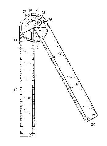
13 FIG. 5 is a schematic view illustrating the
14 operation of the drawing instrument.
Referring to FIGS. 1 to 3, a drawing instrument
16 comprises two rulers 10, 20 each having a head portion
17 11, 21 formed on one end thereof, each of the head
18 portions 11, 21 preferably occupies three quarters of a
19 circle, in which one of the head portions 11 includes a
circular protrusion 12 formed thereon, and the other of
21 the head portions 21 has a circular recess 22 formed
22 therein îor engagement with the circular protrusion 12
23 such that the rulers 10, 20 are rotatable relative to
24 each other by the slidable engagement between the
circular protrusion 12 and the circular recess 22.
26 Each of the head portions 11, 21 includes a hole
27 14, 24 formed in the center thereof respectively such
28 that the user can see through the center of the head
29
~ - :
" : ,~ ',, ~:
. . .
:
,

2~82~92
l portions 11, 21 and such that the center of the head
2 portions 11, 21 can be aligned with any center point
3 drawn in a surface, hest shown in FIG. 3. A pin
4 element, for example, as shown in the drawings, a bolt
15 is engaged in the head portion 11 of the first ruler
6 10, and the head portion 21 second ruler 20 includes an
7 arcuate slot 25 formed therein for engagement with the
8 bolt 15, such that the two rulers 10, 20 can further by
9 coupled together without separation each form the
other, best shown in FIG. 4. An angular graduation 16
11 is formed in the head portion 11 of the first ruler 10,
12 and the head portion 21 of the second ruler 20 includes
13 a convex lens 26 formed thereon in order to enlarge the
14 angular graduation 16. A pointer 28 is formed in the
head portion 21 of the second ruler 20 for indicating a
; 16 value of the angular graduation 16 coxresponding to the
17 relative rotational position between the two head
18 portions 11, 21 of the rulers 10, 20.
19 In operation, referring next to FIG. 5, the first
ruler 10 is pressed against a surface to be drafted
21 with lines and angles, the second ruler 20 can be
22 rotated relative to the first ruler 10, for example, as
23 shown in this drawing, the pointer 28 indicates 30
24 degrees, i.e., the second ruler 20 rotates 30 degrees
relative to the first ruler 10, such that an angle with
26 30 degrees can be easily drafted. Similarly, any angle
27 up to 180 degrees can be easily drafted. The angles can
28 be easily drafted without removing the drawing
29
.... .. . . .

^ 2~8219~
1 instrument.
2 Accordingly, any lines and angular lines can be
3 easily and quickly drafted with the drawing instrument.
4 Although this invention has been described with a
certain degree of particularity, it is to be understood
6 that the present disclosure has been made by way of
7 example only and that numerous changes in the detailed
8 construction and the combination and arrangement of
9 parts may be resorted to without departing from the
spirit and scope of the invention as hereinafter
11 claimed.
12
13
14
16
17
18
19
21
22
23
24
26
27
28
29
', , : ~ , ,' :. -
.. . .

Dessin représentatif
Une figure unique qui représente un dessin illustrant l'invention.
États administratifs

2024-08-01 : Dans le cadre de la transition vers les Brevets de nouvelle génération (BNG), la base de données sur les brevets canadiens (BDBC) contient désormais un Historique d'événement plus détaillé, qui reproduit le Journal des événements de notre nouvelle solution interne.

Veuillez noter que les événements débutant par « Inactive : » se réfèrent à des événements qui ne sont plus utilisés dans notre nouvelle solution interne.

Pour une meilleure compréhension de l'état de la demande ou brevet qui figure sur cette page, la rubrique Mise en garde , et les descriptions de Brevet , Historique d'événement , Taxes périodiques et Historique des paiements devraient être consultées.

Historique d'événement

Description Date
Inactive : CIB de MCD 2006-03-11
Le délai pour l'annulation est expiré 1997-11-05
Demande non rétablie avant l'échéance 1997-11-05
Réputée abandonnée - omission de répondre à un avis sur les taxes pour le maintien en état 1996-11-05
Toutes les exigences pour l'examen - jugée conforme 1995-10-25
Exigences pour une requête d'examen - jugée conforme 1995-10-25
Demande publiée (accessible au public) 1994-05-06

Historique d'abandonnement

Date d'abandonnement Raison Date de rétablissement
1996-11-05
Titulaires au dossier

Les titulaires actuels et antérieures au dossier sont affichés en ordre alphabétique.

Titulaires actuels au dossier
TIEN J. CHOW
Titulaires antérieures au dossier
S.O.
Les propriétaires antérieurs qui ne figurent pas dans la liste des « Propriétaires au dossier » apparaîtront dans d'autres documents au dossier.
Documents

Pour visionner les fichiers sélectionnés, entrer le code reCAPTCHA :


Pour visualiser une image, cliquer sur un lien dans la colonne description du document. Pour télécharger l'image (les images), cliquer l'une ou plusieurs cases à cocher dans la première colonne et ensuite cliquer sur le bouton "Télécharger sélection en format PDF (archive Zip)" ou le bouton "Télécharger sélection (en un fichier PDF fusionné)".

Liste des documents de brevet publiés et non publiés sur la BDBC .

Si vous avez des difficultés à accéder au contenu, veuillez communiquer avec le Centre de services à la clientèle au 1-866-997-1936, ou envoyer un courriel au Centre de service à la clientèle de l'OPIC.


Description du
Document 
Date
(aaaa-mm-jj) 
Nombre de pages   Taille de l'image (Ko) 
Abrégé 1995-04-13 1 14
Dessins 1995-04-13 4 87
Revendications 1995-04-13 2 69
Description 1995-04-13 4 128
Dessin représentatif 1998-08-16 1 14
Taxes 1996-12-10 1 48
Taxes 1995-10-12 1 47
Taxes 1994-10-31 1 46