Sélection de la langue

Search

Sommaire du brevet 2083482 

Énoncé de désistement de responsabilité concernant l'information provenant de tiers

Une partie des informations de ce site Web a été fournie par des sources externes. Le gouvernement du Canada n'assume aucune responsabilité concernant la précision, l'actualité ou la fiabilité des informations fournies par les sources externes. Les utilisateurs qui désirent employer cette information devraient consulter directement la source des informations. Le contenu fourni par les sources externes n'est pas assujetti aux exigences sur les langues officielles, la protection des renseignements personnels et l'accessibilité.

Disponibilité de l'Abrégé et des Revendications

L'apparition de différences dans le texte et l'image des Revendications et de l'Abrégé dépend du moment auquel le document est publié. Les textes des Revendications et de l'Abrégé sont affichés :

  • lorsque la demande peut être examinée par le public;
  • lorsque le brevet est émis (délivrance).
(12) Brevet: (11) CA 2083482
(54) Titre français: APPAREIL POUR MESURER LE DEBIT D'UN FLUIDE
(54) Titre anglais: APPARATUS FOR MEASURING THE FLOWRATE OF A FLUID
Statut: Périmé et au-delà du délai pour l’annulation
Données bibliographiques
(51) Classification internationale des brevets (CIB):
  • G01F 01/56 (2006.01)
  • G01F 01/60 (2006.01)
  • G01F 01/64 (2006.01)
(72) Inventeurs :
  • NISSEN, PETER (Allemagne)
  • KIENE, WILFRIED (Allemagne)
(73) Titulaires :
  • FISCHER & PORTER COMPANY
(71) Demandeurs :
  • FISCHER & PORTER COMPANY (Etats-Unis d'Amérique)
(74) Agent: NORTON ROSE FULBRIGHT CANADA LLP/S.E.N.C.R.L., S.R.L.
(74) Co-agent:
(45) Délivré: 1999-07-20
(22) Date de dépôt: 1992-11-20
(41) Mise à la disponibilité du public: 1993-05-23
Requête d'examen: 1996-04-09
Licence disponible: S.O.
Cédé au domaine public: S.O.
(25) Langue des documents déposés: Anglais

Traité de coopération en matière de brevets (PCT): Non

(30) Données de priorité de la demande:
Numéro de la demande Pays / territoire Date
91 119 972.7 (Office Européen des Brevets (OEB)) 1991-11-22

Abrégés

Abrégé anglais


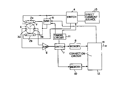
Circuitry for a device to measure the flowrate
of a fluid containing electrical charges which flows in a
pipe section. The device includes at least one
electromagnet connected to a current source which
generates a magnetic field through the pipe section and
at least two electrodes whose central imaginary
connecting line passes through the flow stream in the
region of the magnetic field to measure the potential
resulting from the charge displacements. The circuitry
also includes a timing circuit which periodically changes
the strength of the excitation current from the current
source to the electromagnet and switches a signal shunt
which is connected between the electrodes and at least
two signal memories. The timing circuit also controls a
current sink which is connected in parallel with the
electromagnet. The two signal memories, which store
signals from the electrodes, are connected to a
correction circuit to which the signals stored in the
memories are supplied to produce an output signal
corresponding to the flowrate of the fluid in the pipe
section which is only minimally dependent of the flow
profile or the level of the fluid in the pipe section.

Revendications

Note : Les revendications sont présentées dans la langue officielle dans laquelle elles ont été soumises.


The embodiments of the invention in which an
exclusive property or privilege is claimed are defined as
follows:
1. Apparatus for measuring the flowrate of a fluid
containing electrical charges, said apparatus comprising:
a pipe section through which said fluid containing
electrical charges flows;
at least one electromagnet for generating a
magnetic field extending through said pipe section;
current supply means for supplying an excitation
current to said electromagnet;
a current sink selectively connectable in parallel
with said electromagnet and through which a portion of said
excitation current passes when said sink is connected in
parallel with said electromagnet;
means, including at least two electrodes disposed
along a line passing through said pipe section in the region
of said magnetic field, for generating signals
representative of displacements of electrical charges in
said fluid;
a timing circuit for selectively connecting said
current sink in parallel with said electromagnet to draw a
portion of said excitation current through said sink and
thereby change the level of said excitation current supplied
to said electromagnet;
and a correction circuit responsive to said
signals representative of displacements of electrical
charges in said fluid for developing an output signal
representative of the flowrate of said fluid in said pipe
section, whereby said output signal is only minimally
dependent on the flow profile or the level of the fluid in
the pipe section.
2. Apparatus according to claim 1 further including
means extending between said correction circuit and said
sink for controlling the amount of excitation current
passing through said sink.

3. Apparatus according to claim 2 wherein said signal
generating means further include:
(a) first and second signal memories for storing
signals from said electrodes and for supplying
said signals representative of displacements of
electrical charges in said fluid to said
correction circuit, and
(b) a signal switching element connected between said
electrodes and said signal memories and responsive
to said timing circuit for selectively directing
signals from said electrodes to said first signal
memory when said sink is not connected in parallel
with said electromagnet and to said second signal
memory when said sink is connected in parallel
with said electromagnet.
4. Apparatus according to claim 3 wherein said
current supply means include a direct current source and a
reverse/off switch.
5. Apparatus according to claim 3 wherein said
current supply means include an alternating current source.
6. Apparatus for measuring the flowrate of a fluid
containing electrical charges, said apparatus comprising:
a pipe section through which said fluid containing
electrical charges flows;
a pair of electromagnets for generating a magnetic
field extending through said pipe section;
current supply means for supplying an excitation
current to said electromagnets;
a current sink selectively connectable in parallel
with one of said electromagnets and through which a portion
of said excitation current passes when said sink is
connected in parallel with said one electromagnet;

means, including a pair of electrodes disposed
along a line passing through said pipe section in the region
of said magnetic filed, for generating signals
representative of displacements of electrical charges in
ssaid fluid;
a timing circuit for selectively connecting said
current sink in parallel with said one electromagnet to draw
a portion of said excitation current through said sink and
thereby change the level of said excitation current supplied
to said electromagnet;
and a correction circuit responsive to said
signals representative of displacements of electrical
charges in said fluid for developing an output signal
representative of the flowrate of said fluid in said pipe
section, whereby said output signal is only minimally
dependent on the flow profile or the level of the fluid in
the pipe section.
7. Apparatus according to claim 6 further including
means extending between said correction circuit and said
sink for controlling the amount of excitation current
passing through said sink.
8. Apparatus according to claim 7 wherein said signal
generating means further include:
(a) first and second signal memories for storing
signals from said electrodes and for supplying
said signals representative of displacements of
electrical charges in said fluid to said
correction circuit, and
(b) a signal switching element connected between said
electrodes and said signal memories and responsive
to said timing circuit for selectively directing
signals from said electrodes to said first signal
memory when said sink is not connected in parallel
with said one electromagnet and to said second
signal memory when said sink is connected in

parallel with said one electromagnet.
9. Apparatus according to claim 8 wherein said
current supply means include a direct current source and a
reverse/off switch.
10. Apparatus according to claim 8 wherein said
current supply means include an alternating current source.
11. A device to measure the flowrate of a fluid
containing electrical charges which flows in a pipe section
in which the device includes at least one electromagnet
connected to a current source, which generates a magnetic
field through the pipe section and contains at least two
electrodes to measure the potential resulting from the
charge displacements whose central imaginary connecting line
passes through the flow stream in the region of the magnetic
field, and contains a timing circuit which periodically
changes the strength of the excitation current from the
current source to the electromagnet and switches a signal
switching element which is connected between the electrodes
and at least two signal memories which are connected to a
correction circuit, which from the signals stored in the
memories produces an output signal corresponding to the
flowrate of the fluid in the pipe section which is only
minimally dependent on the flow profile or the level of the
fluid in the pipe section, wherein a timing circuit
controlled current sink is connected in parallel with the
electromagnet and a portion of the excitation current passes
through the timing circuit controlled current sink when the
timing circuit controlled current sink is connected in
parallel with the electromagnet.
12. A device in accordance with claim 11 wherein the
current sink is also controlled by the correction circuit.

13. A device in accordance with claim 12 wherein the
current source is a direct current source and there is
located between the direct current source and the
electromagnet a reverse/off switch controlled by the timing
circuit.
14. A device in accordance with claim 12 wherein the
current source is an alternating current source.

Description

Note : Les descriptions sont présentées dans la langue officielle dans laquelle elles ont été soumises.


2083~8~
FAP-280
CIRCUITRY FOR A DEVIC~ TO MEASURE THE FLQWRATE-
QF FI.I,IDS WITH ELECTRICAL CHARGES
BACKGROUND OF THE INVENTION
The present invention relates to a circuit for
a device to measure the flowrate of a fluid containing
electrical charges which flows in a pipe section. Such a
device includes (1) at least one electromagnet connected
to a current source which generates a magnetic field
through the pipe section, (2) at least two electrodes
whose central imaginary connecting line passes through
the flow stream in the region of the magnetic field to
measure the potential resulting from the charge
displacements in the flowing fluid, and (3) a timing
circuit which periodically changes the strength of the
Jp-026 ~ FAP-280\PArO03
.. .. . . . .

2083~82
FAP-280 - 2 -
excitation current from the current source to the
electromagnet and switches a signal shunt which is
connected between the electrodes and at least two signal
memories which are connected to a correction circuit,
which, from the signals stored in the memories, produces
an output signal corresponding to the flowrate of the
fluid in the pipe section which is only m;nlm~l ly
dependent on the flow profile or the level of the fluid
in the pipe section.
The known electromagnet described in
DE-OS 27 43 954 can be deenergized or have its polarity
reversed to change the magnetic field in the pipe section
and thereby develop a correction function from the
signals coming from the electrodes, with which it is
possible to produce an output signal corresponding to the
flowrate of the fluid in the pipe section which is
essentially independent of the flow profile.
A similar circuit arrangement for a pipe
section is known from EP-0451 30~ Al, which contains two
pairs of electrodes with which the level of the fluid in
the pipe section can be determined and through a
correction function develop an output signal which is
essentially independent of the flow profile in the flow
stream and/or the level of the fluid in the pipe section.

2083~2
FAP-280 - 3 -
SUMMARY OF THE INVENTION
An object of the present invention is to
provide a circuit arrangement for a device to measure the
flowrate of a fluid cont~;n;ng electrical charges which
flows in a pipe section which i9 relatively simple and
permits the use of a higher order parameter correction
function.
Thi~ object is achieved by a circuit
arrangement which is characterized by a timing circuit
controlled current sink connected in parallel with the
electromagnet.
The connection of a current sink in a circuit
is technically simple to accomplish. Furthermore, a
current sink can be very easily structured to provide
different correction functions, so that it is preferred
to control the current sink from the correction circuit.
To produce an alternating current in the electromagnet,
the current source can, in the simplest case, be an
alternating current source. A direct current source can
also be u~ed and a reverse/off switch, controlled by the
timing circuit, can be connected between the direct
current source and the electromagnet to prevent any
undesirable polarization potentials from being generated
at the electrodes.

20834~2
FAP-280 - 4 -
The invention will be described by the
following example with reference to the drawings.
BRIEF DESCRIPTION OF THE DRAWINGS
Fig. 1 is a diagram, primarily in block
form, of the circuit arrangement
of the present invention.
Fig. lA is a block diagram of a
modification to a portion of the
circuit arrangement of Fig. 1.
Fig. 2 shows the current/time
relationship through both
electromagnets for the circuit
arrangement of Fig. 1 when the
electromagnets have aiding
polarities and the current sink
is controlled.
Fig. 3 shows the current/time
relationship through the
electromagnets when the
electromagnets are excited
alternately with opposite
polarities with both

FAP-280 5 2 ~ ~ 3 4 ~ 2
electromagnets having the same
polarity.
Figs. 4 and 5 show two different current/time
relationships through the
electromagnets with the current
sink connected in parallel, for
two different flow profiles or
levels in the pipe section.
DETAILED DESCRIPTION OF THE INVENTION
Fig. 1 shows a pipe section 1 that has, on its
inner surface, an electrically insulating material and
two electromagnets 2a, 2b, outside the pipe section 1, to
generate a magnetic field in the pipe section 1
essentially diametrical along a central axis Y. Two
electrodes 3a, 3b, influenced by the charge difference in
the fluid, are arranged so that an imaginary line X
connecting their centers passes diametrically through the
flow stream and is perpendicular to the central axis Y of
the electromagnets 2a, 2b.
The electromagnets 2a, 2b are connected in
series to a direct current source 13 through the
reverse/off switch 4. A current sink is connected in
parallel to the electromagnet 2a. AS shown in Fig. lA,

- 6 - ~ 8 2
the current source can, in the simplest case, be an
alternating current source 15.
The signals from an amplifier 6, connected
to the electrodes 3a, 3b, are fed to a signal switching
element 7 which sends these signals to a first memory 8
or a second memory 10 dependent upon the output pulse
of the timing circuit 11. The signals stored in the
memories 8, 10 are fed to a correction circuit 12 which
produces an output signal at output 14.
The timing circuit 11 and the correction
circuit 12 control the current sink. Additionally,
the reverse/off switch 4 is controlled by the timing
circuit 11.
Assuming a constant fluid flow through a full
pipe section 1, when only one of the electromagnets is
energized, the output from the electrodes is one-half
the output from the electrodes when both electromagnets
are energized. Reversing the current in one of the
electromagnets, reduces the output from electrodes and
when the opposing currents are equal, the output from
the electrodes is zero.
For a half-full pipe section 1, the lower half
of the pipe section has conductive fluid, while the upper
half of the pipe section has nonconductive air. Despite
~.. .
.

~ 2~3482
FAP-280 - 7 -
the fact that the volume of fluid flow is half of that
for a full pipe section, the output from the electrodes
of a conventional magnetic flowmeter, when both
electromagnets are energized, is the same as for a full
pipe section, so that the flowrate reading is off by 100~
Because magnetic field strength is greater at a
point close to an electromagnet than at a remote point,
for a partially full pipe section, the lower
electromagnet contributes more to the outputs from the
electrodes than does the upper electromagnet. This
asymmetrical arrangement for a partially full pipe
section results in an imbalance of the partial electrode
signals. This problem can be overcome by varying the
excitation current supplied to one of the electromagnets,
so as to differentiate the normal outputs from the
electrodes obtained in the usual electromagnet excitation
mode from the outputs from the electrodes when the
excitation current in one of the electromagnets has been
reduced to detect a partially filled pipe section or
distorted flow profiles.
Referring to Figs. 2 and 3, the current J2a in
electromagnet 2a is reduced at a specific time by use of
the current sink 5. This is indicated by the time
periods designated I and II in Figs. 2 and 3. The amount
of the reduction is a function of the signal received by
the current sink 5 from the correction circuit 12. The
. .

20834~2
FAP-280 - 8 -
signals from amplifier 6 are fed to memory 8 during time
period I and to memory 10 during time period II. During
a calibration procedure on a flow test rig, the sizes of
the signals stored in memories 8 and 10 under differing
S fill-states of the pipe section can be determined
empirically. The case shown in Fig. 2 is for an
undisturbed flow profile and a full pipe condition in the
pipe section 1 and the case shown in Fig. 3 is for a
disturbed flow profile and/or a partially full pipe
condition in the pipe section 1.
Fig. 2 shows the current J2a and J2b time t
relationship for both electromagnets for synchronized
aiding excitation. In the time period I, the current
sink 5 i9 not active. The current sink 5 is active in
the time period II.
Fig. 3 show~ the current J2a and J2b time t
relationship for both electromagnets for synchronized
alternating pulse excitation. In the time periods I and
III, the current sink 5 is not in use. The current sink
5 is active in the time periods II and IV.
Fig. 4 shows the current J2a time t
relationship for the electromagnet 2a for an undisturbed
flow profile and full pipe condition in the pipe section
1 in the time periods I and II.

2083~82
FAP-280 - 9 -
Fig. 5 shows the current J2a time t
relationship for a disturbed flow profile and/or
partially full pipe condition in the pipe section 1.
The nature of the magnetic field in the pipe
section 1 is changed within the time periods I and II in
order to provide different signals to the correction
circuit 12 to develop the correction function. The
reduction in excitation current can be fixed or variable
in response to correction circuit 12 which, in essence,
can be arranged as a "look-up table" from which a control
of sink 5 is provided. For a relatively full pipe
section, sink 5 reduces the excitation current to
electromagnet 2a only slightly, while, for partially full
pipe sections, sink 5 reduces the excitation current to
electromagnet 2a to a greater extent dependent upon the
degree of filling of the pipe section.
If, for example, a signal from an undisturbed
flow profile exists, then the reduction of the current
through the electromagnet 2a can be m;nlm~l, just
sufficient, to allow a determination of a change in the
flow profile as time passes. An evaluation circuit, to
which the potential between the electrodes is fed,
receives, during the time periods I and II, a large
signal which is desired for an accurate flow measurement.
The reduction of the current through the electromagnet 2a
is a function of the degree of the flow profile

2~3482
FAP-280 - 10 -
disturbance. The greater the disturbance, the greater
the current reduction in the electromagnet 2a.

Dessin représentatif
Une figure unique qui représente un dessin illustrant l'invention.
États administratifs

2024-08-01 : Dans le cadre de la transition vers les Brevets de nouvelle génération (BNG), la base de données sur les brevets canadiens (BDBC) contient désormais un Historique d'événement plus détaillé, qui reproduit le Journal des événements de notre nouvelle solution interne.

Veuillez noter que les événements débutant par « Inactive : » se réfèrent à des événements qui ne sont plus utilisés dans notre nouvelle solution interne.

Pour une meilleure compréhension de l'état de la demande ou brevet qui figure sur cette page, la rubrique Mise en garde , et les descriptions de Brevet , Historique d'événement , Taxes périodiques et Historique des paiements devraient être consultées.

Historique d'événement

Description Date
Inactive : CIB expirée 2022-01-01
Le délai pour l'annulation est expiré 2006-11-20
Inactive : CIB de MCD 2006-03-11
Lettre envoyée 2005-11-21
Inactive : TME en retard traitée 2002-11-20
Lettre envoyée 2001-11-20
Accordé par délivrance 1999-07-20
Inactive : Page couverture publiée 1999-07-19
Inactive : Taxe finale reçue 1999-04-14
Préoctroi 1999-04-14
Un avis d'acceptation est envoyé 1999-02-11
Lettre envoyée 1999-02-11
Un avis d'acceptation est envoyé 1999-02-11
Inactive : Renseign. sur l'état - Complets dès date d'ent. journ. 1999-02-03
Inactive : Dem. traitée sur TS dès date d'ent. journal 1999-02-03
Inactive : CIB attribuée 1998-12-18
Inactive : Approuvée aux fins d'acceptation (AFA) 1998-12-15
Toutes les exigences pour l'examen - jugée conforme 1996-04-09
Exigences pour une requête d'examen - jugée conforme 1996-04-09
Demande publiée (accessible au public) 1993-05-23

Historique d'abandonnement

Il n'y a pas d'historique d'abandonnement

Taxes périodiques

Le dernier paiement a été reçu le 1998-10-20

Avis : Si le paiement en totalité n'a pas été reçu au plus tard à la date indiquée, une taxe supplémentaire peut être imposée, soit une des taxes suivantes :

  • taxe de rétablissement ;
  • taxe pour paiement en souffrance ; ou
  • taxe additionnelle pour le renversement d'une péremption réputée.

Les taxes sur les brevets sont ajustées au 1er janvier de chaque année. Les montants ci-dessus sont les montants actuels s'ils sont reçus au plus tard le 31 décembre de l'année en cours.
Veuillez vous référer à la page web des taxes sur les brevets de l'OPIC pour voir tous les montants actuels des taxes.

Historique des taxes

Type de taxes Anniversaire Échéance Date payée
TM (demande, 5e anniv.) - générale 05 1997-11-20 1997-10-28
TM (demande, 6e anniv.) - générale 06 1998-11-20 1998-10-20
Taxe finale - générale 1999-04-14
TM (brevet, 7e anniv.) - générale 1999-11-22 1999-10-27
TM (brevet, 8e anniv.) - générale 2000-11-20 2000-10-16
TM (brevet, 9e anniv.) - générale 2001-11-20 2002-11-20
TM (brevet, 10e anniv.) - générale 2002-11-20 2002-11-20
Annulation de la péremption réputée 2001-11-20 2002-11-20
TM (brevet, 11e anniv.) - générale 2003-11-20 2003-10-20
TM (brevet, 12e anniv.) - générale 2004-11-22 2004-10-26
Titulaires au dossier

Les titulaires actuels et antérieures au dossier sont affichés en ordre alphabétique.

Titulaires actuels au dossier
FISCHER & PORTER COMPANY
Titulaires antérieures au dossier
PETER NISSEN
WILFRIED KIENE
Les propriétaires antérieurs qui ne figurent pas dans la liste des « Propriétaires au dossier » apparaîtront dans d'autres documents au dossier.
Documents

Pour visionner les fichiers sélectionnés, entrer le code reCAPTCHA :


Pour visualiser une image, cliquer sur un lien dans la colonne description du document. Pour télécharger l'image (les images), cliquer l'une ou plusieurs cases à cocher dans la première colonne et ensuite cliquer sur le bouton "Télécharger sélection en format PDF (archive Zip)" ou le bouton "Télécharger sélection (en un fichier PDF fusionné)".

Liste des documents de brevet publiés et non publiés sur la BDBC .

Si vous avez des difficultés à accéder au contenu, veuillez communiquer avec le Centre de services à la clientèle au 1-866-997-1936, ou envoyer un courriel au Centre de service à la clientèle de l'OPIC.


Description du
Document 
Date
(aaaa-mm-jj) 
Nombre de pages   Taille de l'image (Ko) 
Dessin représentatif 1999-07-13 1 7
Abrégé 1994-03-25 1 28
Revendications 1994-03-25 7 171
Description 1994-03-25 10 246
Dessins 1994-03-25 3 43
Revendications 1998-12-01 5 186
Description 1998-12-01 10 283
Dessins 1998-12-01 2 31
Avis du commissaire - Demande jugée acceptable 1999-02-10 1 163
Avis concernant la taxe de maintien 2001-12-17 1 178
Quittance d'un paiement en retard 2002-11-25 1 166
Avis concernant la taxe de maintien 2006-01-15 1 172
Taxes 2002-11-19 2 82
Correspondance 1999-04-13 1 49
Taxes 1996-10-31 1 58
Taxes 1995-10-26 1 67
Taxes 1994-11-13 1 58
Correspondance de la poursuite 1996-10-08 4 96
Correspondance de la poursuite 1996-04-08 1 44
Courtoisie - Lettre du bureau 1996-04-30 1 49
Courtoisie - Lettre du bureau 1993-04-18 1 15