Note : Les descriptions sont présentées dans la langue officielle dans laquelle elles ont été soumises.
2~3~
DI8PhAY CARD ~OLDER
BACKGROUND OF TH~ INVENTION
My invention provides a display card holder or
mounting apparatus for releasably mounting a display
card, advertisement, sign, poster, etc. The mounting
apparatus serves as a permanent, tamper proo~, message
holder for inexpensive point of purchase material in
a high risk exposure retail environment. In
particular, the mounting apparatus is positioned at a
location such that the display card, etc., is readily
visible to consumers, e.g., on top of a cash register
or counter top.
In general, it is known to support a display card
or sign in commercial establishments by means of a
releasable mounting device. Such display cards
normally include indicia thereon for advertising or
promoting a particular product. For example, U.S.
Patent No. 5,031,870 (Higgins) discloses a display
card mou~ting device for releasably supporting cards,
signs and the like. The device includes a card
engaging member movable between a card retaining
position and a card releasing position, and manually
operated tabs ~or operating the card engaging member.
U.S. Patent No. 4,473,963 (Hardy et al) discloses
2s a sign support ~or releasably attaching a sign to a
display stand.
U.S. Patent No. 2,268,077 (Leonard et al)
discloses a holder for use on restaurant counters and
tables for holding menus in an upright position, and
which is also designed ~or holding salt, pepper and
sugar shakers. The holder includes a one piece tray
having a trough ~or receiving menus. A clamping plate
is provided in the trough and cooperates with a rear
side of the trough to clamp the lower edges of the
3s menus.
.
2~83~
U.S. Patent No. 715,532 (Anderson) discloseR a
card holder for receiving menu-cards, photographs, and
the like. The card holder includes a body having a
transverse slot therein. A spring is secured to the
s ~ody and extends down into the slot.
SUMMARY OF THE INVENTION
It is an object of the present invention to
provide a display card holder or mounting apparatus
o for releasably mounting a display card, advertisement,
sign, poster, etc. The mounting apparatus provides a
simple and inexpensive means for supporting a card or
sign used in advertising or promoting a product and
the like, the holder being aesthetically pleasing to
S the eye.
In particular, the holder includes a support
means in the form o~ a stand, and a substantially
hollow, elongated housing having a body portion and
first and second end walls. The housing is connected
to the stand at the ~irst and sQcond end walls by
fastening means, so as to allow for angular adjustment
of the housing and display card or sign with re~pect
to the ~tand. The housing include~ a longitudinal
slot for receiving the display card or sign and which
2s extends along an upper surSace o~ said body portion
between ~aid first and second end walls. Each of the
first and second end walls of the housing includes an
opening or window. First and second end pieces
re~pectively pass through the corresponding openings
in the first and second end walls and are ~lidably
supported on guide means disposed within the housing.
Each end piece comprises a pinching mechanism
including a bi~urcated member having a gap ~or receiv-
ing and pinching the lower edge o~ the display card.
2 ~
Each end piece further includes a locking member for
engaging a corresponding notch in the display card.
BRIEF DEscRIp~loN OF THE DRAW~NGS
Other features and advantages of the present
invention will be apparent from the following
description taken in connection with the accompanying
drawings wherein:
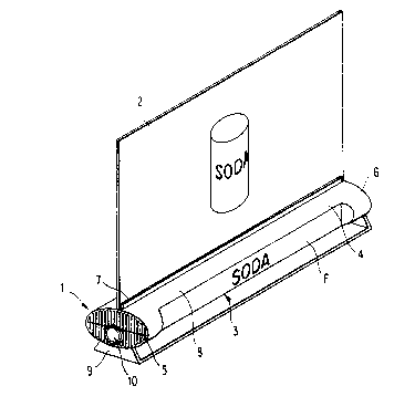
Fig. 1 is a perspective view of the display card
holder according to the present invention;
Fig. 2 is an exploded view of the display card
holder including a fragmentary view of the display
card or sign;
Fig. 3 is a cross sectional view through one end
portion of the holder housing;
Fig. 4A is a top view of the left side end pieca
of the holder;
Fig. 4B is an end view of the left ~ide end piece
in the direction 4B-4B in Fig. 4A;
Fig. 4C is a cross sectional view through the
left side end piece along the l$ne 4C-4C in Fig. 4A;
Fig. SA is a fragmentary top view of the rear
portion or cabinet of the holder;
Fig. 5B i8 a side view of the rear portion or
cabinet Or the holder in the direction 5B-5B in Fig.
5A; and
Fig. 6 is a perspective view showing an
alt-rnativo signage.
DETAILEL DESCRIPTION OF THE PREFERRED EMBODIMENTS
The invention will now be described with
rererence to the drawings. As shown in Fig. 1, tho
display card holder or mounting apparatus i8 generally
denoted by the reference numeral 1. A~ will be
described in moro dotail below, the holder 1 is
designed to releasably support a display card or sign
~8~
2. The display card 2 will normally include indicia
and/or graphics such as indicated by the soft drink
can labeled "SODA". The indicia may be in the form of
an advertisement for a particular product. Likewise,
a picture, logo, etc., could be`displayed on the card
2.
The holder 1 includes a substantially hollow,
elongated housing 3. The housing 3 is preferably
elliptical or oval in cross section, although not
o limited to such a shape, and includes a body portion
4 and first and second end walls 5 and 6,
respectively, with only the first end wall 5 being
visible in Fig. 1. The housing 3 includes a
longitudinal slot 7 for receiving the lower edge of
the display card 2 as will be described in more detail
below. The slot 7 extends along an upper sur~ace 8 of
the body portion 4 between the first and second end
walls 5 and 6.
The housing 3 is adjustably mounted to a support
means in the form of a stand 9 (see Fig. 2) at the
first and second end walls 5 and 6, respectively, by
fastening means 10, 10l. The fastening means may take
the form of a plastic, brass, or aluminum end screw or
thumbscrew for aesthetic rea~on~. The stand 9
comprises a platform 11 and a pair of vertical arms
12, 12' having respective opening~ 13, 13'
ther-through for receiving the shank portiona 14, 14'
of the corre~ponding fastening mean~ 10, 10' (sQe Fig.
2). Double-sided adhesive tape (not shown) is
disposed on the bottom of the platform 11 of the stand
9. Accordingly, once a protective covering i~ peeled
off the tape, the stand 9, along with the holder 1, i9
then adhered to a cash register, counter top or the
like.
.
.
' ' ~
,
~.~33~
The openinqs 13 and 13' each have a brass,
aluminum or plastic screw nut 16 and 16',
respectively, inserted therein. Each nut 16, 16' is
internally threaded for threadingly engaging the
fastening means 10, 10'. Each nut 16, 16' is also
knurled on the outer surface for gripping stand 9 when
press-fitted intG openings 13, 13'. O-rings 17 and
17' are provided as friction devices between the arms
12 and 12', respectively, and the housing 3.
o Of course, the support means could alternatively
be formed by a flat surface on the bottom of the
housing 3 instead of utilizing a separate stand 9.
As shown in Fig. 1, the body portion 4 of the
holder housing 3 may advantageously have a flat
portion F for forming indicia, pictures, etc., thereon
by any suitable process to further promote or
advertise a product, etc. For example, indicia may be
formed on the flat portion by silk-screening, tab
printing or hot foil stamping.
The specific structure of the housing 3 of the
display card holder 1 will now be described with
reference to Figs. 2-5~3.
As shown in Fig. 2, the housing 3 compri3es a
front portion or cabinet 20 and a rear portion or
cabinet 21. The front cabinet 20 i8 formed with the
flat portion F which is an indent in the elliptical
body portion 4. The housing 3 is divided along the
minor axi~ of the ellipse when viewed in cro~s section
(see Fig. 3), such that when the front and rear
3~ portions 20 and 21 are joined together, the elliptical
shaped housing is formed. At the upper edge of each
of the front and rear portions 20 and 21, an upright
flange or lip 22, 23 extends a short distance above
the body portion 4. When the ~ront and rear portions
20 and 21 are ~oined together, the lips 22 and 23
~$~
together form the longitudinal slot 7 therebetween for
receiving the lower edge of the display card 2
At a location generally below the major axis of
the elliptical housing 3 when viewed in cross section
s (see Fig 3), a plurality of hollow bosses 24 (for
example, five) project inwardly from an inner surface
25 of the rear portion 21 The bosses 24 may have a
circular cross section but are not limited to this
shape The bosse~ 24 are equally spaced
o longitudinally along the inner surface 25 of the rear
portion 21 Further, a plurality of corresponding
hollow bosqe~ 26, one of which is shown in Fig 3,
project inwardly from a flat inner surface 27 of the
front portion 20 The bosses 26 are egual in number
to bosses 24 and have a complementary shape thereto
However, the bo~ses 26 are smaller than the bosses 24
such that they may slidably fit into the bosses 24 in
a snug manner by means of a friction fit when the
~ront and rear portions 20 and 21 are joined together
In this way, the bosse~ provida a m~ans for tightly
securing the ~ront and rear portions 20 and 21
togeth-r.
The end walls 5 and 6, in addition to being
divided vertically along the minor axis o~ the ellipsQ
2s so that tho ~ront and rear cabinet~ 20 and 21 are
separabl- th-reat, ar- ~urther sectioned into a lower
~ectlon 30 (l-~t nd in Fig 2), 30' (right end in
Fig 2) and an upper section 31, 31' The part$~ion
lin- b-tween th- upper and lower ~ec~ions 30, 30' and
31, 31' is substantially along the ma~or axis o~ the
ellip~e A~ shown in Fig 2, the lower section 30,
30' compri~es an inner wall 32, 32' and an outer wall
33, 33' which ar- spaced apart 90 as to form a channel
34, 34' therebetw-en The walls 32, 32' and 33, 33'
are joined together by a horizontal connecting wall
.... .
2~8~
35, 35'. Each channel 34, 34' opens outwardly on the
underside of the elliptical housing 3 and is designed
to receive the corresponding arm 12, 12' Or the ~tand
9.
s The lower sections 30, 30' also include through
holes for allowing the thumbscrews 10, 10' to pass
therethrough. The inner wall 32, 32' and outer wall
33, 33' are formed with through holes 36, 36' and 37,
37', re-qpectively, for allowing passage of the shank
o portion 14, 14~ of the corresponding thumbscrew 10,
10'. Accordingly, when the screw nuts 16, 16' of the
arms 12, 12' of the stand 9 are aligned with the
through holes 36, 36' and 37, 37' by inserting the
arms 12, 12' into the corresponding ~hannels 34, 34~,
the thumbscrews 10, 10' are threaded therethrough.
The ~ront cabinet 20 include~ a molded plastic
shoulder 19 ~the right side shoulder is not visible)
disposed in the front half Or through holes 37, 37' of
each outer wall 33, 33'. The shank portions 14, 14'
o~ the thumbscrews pass through the respective
shoulders 19.
The shank port~on 14, 14' Or each thumbscrew 10,
10' includ-~ a groovo g at the free end thereof for
receiving an E-clip 18, 18'. The E-clip 18, 18'
2s simply prev-nt~ the thumbscrew 10, 10' from falling
out o~ th- bolder 1 when loosoned.
Th- upp-r section 31 of end wall 5 is slightly
r-c-~-d such that the edge o~ the housing 3 overhangs
b-yond the upper section 31 (see Fig. 5B) for reasons
di~cussed later on. The upper section 31 also
include~ an opening or window 38 ror allowing an end
piece S0 (de~cribed later) to pas~ therethrough. The
window 38 1~ partly rormod in the end wall portion o~
the rear cabinet 21 and partly rormed in th~ end wall
3s portion Or the rront cabinet 20. Accordingly, when
3 ~
the front and rear cabinets are joined together, a
single window 38 is formed. The upper sectio~ 31' on
the opposite end wall 6 likewiss is recessed and
includes a window 38' for allowing end piece 50' to
s pass therethrough.
Referring to Figs. 3, 5A and 5~, each of the
front and rear cabinets 20 and 21 include~ guide means
at opposite ends thereof in the form of uppar and
lower rail~ R and R'. The rails R and R' extend
o inwardly from the inner surface of the respective
cabinet 20 and 21. The railq R and R' are located
above the bo~ses 24 and 26, with each of the lower
rails R' being flush with the corresponding connecting
wall 35, 35'. Accordingly, when the front and rear
cabinets 20 and 21 are joined together, there are
opposing pairs of rails R, R' disposed at opposite
ends of the elliptical housing 3 (see especially Figs.
3 and 5B). Note, only the rear cabinet 21 i8 shown in
Figs. 5A and 5~ for the sake of brevity. O~ cour~e,
front cabinet 20 i8 substantially similar in
structure, although the ~ront cabinet includes the
flat portion F for forming indicia thereon.
In addition to the bosses 24 and 26, the ~ront
cabinet 20 may lnclude solid pro~ections or pins 40
(only one ot which i8 visibl~ in Fig. 2) at opposite
ends in the vicinity o~ the lip 22. The pins 40 are
ins-rted into corresponding blind bores 41 (sea Fig~.
2 and 5Bl ~ormed at opposite ends of the rear cabinet
21 near the lip 23. The pin~ 40 and blind bore~ 41
provide additional support when the front and rear
cabinets 20 and 21 are ~oined togQther by friction
~it.
The speci~ic structure of the movable end pieces
50 and 50' will now be described with re~erence to
Figs. 2, 3, 4A, 4B and 4C. Since the end piece 50,
~3~
which is disposed in the left end of the housing 3, i9
identical in str~cture to the end piece 50', which is
disposed in the right end of the hou~ing 3, only the
end piece 50 is shown and described.
As best shown in Figs. 2 and 4A, the end piece 50
includes an end plate 51 which is shaped so as to
correspond to the upper half of the ellipse (i.e.,
upper section 31) when viewing the housing 3 from the
left end. The outer surface of the end plate 51 i~
lo formed with a ribbed surface 52. The ribs 53 are
arranged vertically and are designed to align with
corresponding ribs 54 formed in the lower section 30
o~ end wall 5. In this manner, when the end plate 51
iQ pre~sed again~t the upper section 31 of end wall 5,
lS the outer surface o~ the end plate Sl will be flush
with the outer ~ur~ace of the lower section 30. As a
re~ult, the opposite end~ o~ the housing 3 are
ellipses with ribbed sur~aces.
As best shown in Fig. 4B, the end plate 51
include~ a tab T. The tab T ~its into a corresponding
notch N ~orm-d in the edge o~ the hou~ing 3 which
overhangs beyond the upper sQction 31, when the end
plate S1 i~ pre~ed against the upper section 31. The
inner sur~ac- o~ the tab T may be dished out as at 54
(~e- Fig. 4A), ~o a~ to allow a user to insert a
~ingernall therein to pull out the end piece 50.
M-an~ 60 ror pinching the lower edge o~ the
display card 2 extend~ inwardly ~rom an inner ~ace of
the end plate 51. The pinching mean~ 60 comprises a
bi~urcated member 61 having two parallel, spaced-apart
vertical walls 62 and 63 which are each ~ixod at one
end to the inner ~ace o~ the end plate 51 and which
have ~ree end~ 64 and 65 extending into the hollow
housing 3.
2~8'Q~9~
At the location where the two vertical walls 62
and 63 are fixed to the end plate 51, a horizontal
wall 66, which is fixed to tho end plate 51, extends
between an upper portion of the two vertical walls 62
and 63 and connects them together. ~he horizontal
wall 66 extends a predetermined distance toward the
free ends 64, 65 of the vertical walls 62 and 63,
which distance is preferably less than a third of the
distance in which the vertical walls 62 and 63 extend
~o away from the end plate 51, although not limited to
thi~ ratio. The horizontal wall 66 serve as a
locking member for locking the display card into the
holder 1 as will be discussed in more detail later on.
At the base of the vertical walls 62 and 63,
respective rims 67 and 68 extend a short distance
inwardly. A gap G, which corresponds approximately to
the width of a display card, i8 formed between the
rims 67 and 68.
A plurality of vertical ribs 69 are positioned
along the inner sur~aces o~ the two vertical walls 62
and 63. The ribs 69 are arranged in opposing fashion
~uch that pairs o~ opposing ribs are equally spaced
along th- inner surracQ~ o~ the vertical wall~ 62 and
63. The rib~ 69 extend upwardly with respect to the
corre~ponding rim 67, 68 and are perpendicular to the
two vertic~l wall~ 62 and 63. As be~t seen in Figs.
2, 3 and 4B, the upper edges o~ the ribs 69 are
cham~ered a~ at 70. This simply help~ to guide the
low-r edgQ o~ the display card 2 when inserting the
card into the holder 1.
on the outer 6ur~aces o~ the two vertical walls
62 and 63, ledges 71 and 72 extend perpendicularly
~rom the base o~ the corresponding vertical wall. The
ledge 71 i~ alignod with the rim 67 and tho lodge 72
is aligned with the rim 68 (see Fig. 4B). The ledges
2~ ~3
71 and 72 are slidably fitted between the rails R and
R' in rear cabinet 21 and the rails ~ and R' in the
front cabinet 20 (see especially Fig. 3). As shown in
Figs. 4A and 4B, the ledge 71 extends out further from
s the vertical wall 62 than the ledge 72 extend~ from
the vertical wall 63. This simply compensates ~or the
smaller space within the front cabinet 20 due to the
presence of the flat wall portion F.
As shown in Figs. 5A and 5B, a plurality of webs
lo W extend vertically between each of the upper and
lower rails R and R'. The webs W are egually spaced
apart along the rails (e.g., 1-2 mm) and project
inwardly a preset distance which is less than the
di~tance that the rails R and R' project into the
housing 3. As shown in Fig. 5A, the webs W project
inwardly at an increasingly greater distance the
~arther away ~rom the end wall 5 the webs W are
located. Thus, a converging path is formed by the
webs W. Accordingly, when the end plate 51 and
pinching means 60 are moved inwardly by manual
depression, the ledges 71 and 72 slide between the
corresponding railJ R and R'. As the end piece 50
reache~ its ~inal, in~erted po~ition within the
hou~ing 3, the webJ W squeeze the vertical walls 62
and 63 together by engaging the ledges 71 and 72. The
outer edg-~ Or th~ ledges 71 and 72 are bevelled as at
73 and 74 to ~acilitate sliding along the webs W.
Accordingly, the display card 2 is pinched in the gap
G between the two vertical walls.
The display card 2 may be provided with notches
80 and 81. The notch 80 is de~ignod to bQ engaged by
th~ horizontal wall 66 when the end piece 50 is fully
in~erted into the hou~ing 3. In this manner, the wall
66 serves as a locking membsr to lock ~he display card
3s in place in addition to the pinching action o~ the
11
~83~
vertical walls 62 and 63 with respect to the end piece
50 Likewise, the end piece S0' includec a horizontal
wall 66' for engaging the notch 81 oP the display card
The operation of the holder 1 will now be briefly
described below
Before inserting a display card 2 into the holder
1, the left and right end pieces 50 and 50' are
slightly withdrawn from the housing 3 through the
o corresponding window~ 38 and 38~ Thi~ is
accomplished by si~ply grasping the end plate 51 or
51' at the tabs T or T' and pulling the end plate away
~rom the housing The display card 2 is then inserted
into the longitudinal slot 7 and pushed down through
the gap G of the le~t end piece 50 and gap G' of the
right end piece 50' The lower edge of the display
card 2 will continue down through the gaps G, G' until
it rests on top o~ the bosses 24 (see Fig 3)
At this time, the user ~imply pushe~ the end
piece~ S0 and 50' inwardly within the housing 3
During inward movement o~ the end piece 50, the ledges
71 and 72 slide between the rails R and R' and are
pressed togeth-r by the webs W 80 a~ to pinch the
di~play card 2 in the gap G At the ~inal position,
when tbe out-r sur~acQ o~ end plate 51 is ~lu~h with
th~ lower ~octlon 30 o~ the end wall S, the horizontal
wall 66 engage- with the notch 80 so as to lock the
card in plac- Tho operation o~ the end piece 50' is
id-ntical
In ord-r to release the display card 2 ~rom the
holder 1, the u~er simply pull~ out the two end pieces
50 and 50' by gra~ping the corresponding end plates 51
and 51'
~
12
2~83'~
The holder 1 may be formed from any suitable
material but preferably is formed of a plastic, e.g.,
polystyrene (PS).
Further, while the holder 1 is shown in Fiqs. 1
and 2 releasably mounting a display card 2, the card
2 could alternatively be replaced by a transparent
member 202 which includes notches 280, 281 near the
lower edge as shown in Fig. 6. The transparent member
202 has a U-shaped cros~ section with a fold on top.
o The two legs of the U form front and back surfaces 290
and 291 of the transparent member 202, with a small
gap 293 formed therebetween for the purpose of
inserting a sign, advertisement, etc., 294. The
transparent member 202 may be w~lded along the
vertical sides to prevent bowing. The free ends of
the U are inserted into the holder 1 and the notches
280 and 281 are engaged by the end pieces 50 and 51'
in the same manner as the display card 2. The
transparent member 202 may be formed of polycarbonate
or a rigid vinyl.
It is contemplated that numerous modification~
may be mad- to the display card holder of the present
inv-ntion without departing from the spirit and scope
of the invention a~ defined in the ~ollowing claim~.
2S