Note : Les descriptions sont présentées dans la langue officielle dans laquelle elles ont été soumises.
- 1 21~84~7
SPECIFICATION
TITLE OF THE INVENTION
RESTRAINING PROTECTIVE SEAT FOR INFANTS
BAC~GROUND OF THE INVENTION
This invention relates to an infant-restraining
protective seat of the type placed upon and secured to a
seat in a vehicle such as an automobile or airplane and
adapted to restrain and protect a seated infant by
infant-restraining protecting means such as a seat belt
0 device for infants.
In a vehicle such as an automobile or airplane,
restraining protective seats for infants have been used
in order to maintain the seated posture of an infant
during travel and protect the infant from shock at the
time of acceleration and deceleration. An infant
restraining and protective seat of this kind has a
;~recllnable seat main body reclinably attached to a base
member and adapted to~seat an infant, and an infant seat
belt device for restraining the seated infant. The
infant seat~belt device has an infant seat belt, a
chest-contact pad attached to the end of the infant seat
bélt, a tongue provided on the end of the chest-contact
pad, and a buckle, provided on the seat main body,
capable of holding the tongue in such a manner that the
tongue can be freely engaged with and disengaged from
the buckle. In a state in which the tongue is engaged
with and locked by the buckle, the infant is restrained
by the infant seat belt and chest-contact pad.
- 2 - 208~
In the conventional infant-restraining protective
seat of this kind, the sea-t portion for seating the
infant and a seat back which supports the bac~ of the
seated infant are integrally molded from a resin or the
like, and the resulting integrally molded article is
reclinably attached to the base portion. Since the seat
portion and the seat back are thus formed from an
integrally molded article, the conventional infant-
restraining protective seat inevitably is large in size.
0 However, the fact that the infant-restraining
protective seat is large in size makes it very difficult
to carry and to set up on the seat of the vehicle. In
addition, since the protective seat requires a large
storage space owing to its large size, it is difficult
to keep the seat in storage. Storage space is a major
problem especially in vehicles such as automobiles, in
which the amount of available space is limited.
~ILMI~LL~ L5L~ 3~5~
An object of the present invention is to provide an
infant-restraining protective seat capable of being
reduced in size when not in use so as to be made easy to
carry and set up on the seat of a vehicle, such a seat
also requiring little storage space.
According to the present invention in a first
aspect thereof, the foregoing object is attained by
providing an infant-restraining protective seat
comprising a seat portion for seating an infant, a seat
back for supporting the back of the seated ~nfant, and
_ 3 _ 20~ 7
infant restraining means such as an i.nfant seat belt
device for restraining and protecting the seated infant,
characterized i.n that the seat back is tiltably attached
to the seat portion and the seat portion and seat back
S are adapted so as to be foldable; locking means is
provided for locking -the seat back at a prescribed
backward tilt angle, the locking means having a through-
hole provided in the seat portion, a locking hole
provided in the seat back so as to correspond to the
prescribed backward tilt angle, and a locking pin that
is passed through the through-hole and the locking hole,
the locking hole being formed as an elongated hole such
as of elliptical shape having a minor axis in the
tilting direction of the seat back and a major axis in a
diametric direction.
In the~infant-restraining protective seat according
to the present invent~ion constructed as set forth above,
the seat portion for seating the infant and the seat
: ~ back for supporting the back of the seated infant are
capable of being folded. ~hen the infant--estraining
protective seat is not in use, the protective seat can
- be reduced in size by folding the seat portion and the
seat back. Since the protective seat thus folded up
into a small size is accommodated and stored in this
condition, the protective seat can be carried about and
set up on a seat much more easily. In addition, only a
small amount of space is necessary for storage.
E'urther, the arrangement is such that after the
_ 4 _ 2~84~7
seat back has been tilted backward in order to set it at
the prescribed reclining position, the locking pin is
in.ser-ted into the locking hole, whereby the seat back
can be locked at the prescribed reclining angle. In
this case, the locking hole is formed as an elongated
hole whose minor axis lies in the tilting direction of
the seat back. As a result, play of the seat back in~
the tilting direction is reduced.
Still other objects and advantages of the invention
will in part be obvious and will in part be apparent
from the specification.
The invention accordingly comprises the features of
construction, combinations of elements and arrangement
of parts which will be exemplified in the construction
hereinafter set forth, and the scope of the invention
will be indicated in the claims.
BRIEF DESCRIPTION OF THE DRAWINGS
Fig. 1 is a front view showing an embodiment of an
infant-restraining protective seat according to the
present invention, in which the left half of the seat
has been cut awayi
Fig. 2 is a side view showing this embodiment with
a portion thereof cut away;
Fig. 3 is a plan view showing this embodiment with
a portion thereof cut away;
Fig. 9 is a plan view showing the main body of a
seat portion in this embodiment;
Fig. 5 is a side view showing the main body of the
2~8~4~7
seat portioni
Fig. 6 is a sectional view of the main body of the
seat portion taken along line VI-VI in Fig. 4;
Fig. 7 is a front view showing the main body of a
S seat portion;
Fig. 8 is a perspective view showing a base portion
in this embodiment;
Fig. 9 is a front view showing a seat back in this
embodiment;
Fig. 10 is a side view of the seat back;
Fig. 11 is a plan view of the seat back;
Fig. 12 is a side view schematically showing the
protective seat of the embodiment in the folded state;
Eig. 13 is a front view schematically showing the
protective seat of the embodiment in the folded state;
Fig. 14 illustrates an upper bracket in this
embodiment, in which (a) is a plan~ view thereof and ~b)
an enlarged view of a locking hole;
Fig. 15 illustrates a lower bracket in this
embodiment, in which (a) is a front view thereof and (b)
a plan view;
Fig. 16 is an explanatory view for describing the
spring characteristic o a torsion spring in this
embodiment;
Fig. 17 illustrates an operating lever of a seat-
back tilting control device in this embodiment, in which
(a) is a side view thereof and (b) a front view;
Fig. 18 is a view showing a locking pin in this
2084~L~7
-- 6
embodimenti
Fig. :19 illustrates a cam plate of the seat-back
tilting control device in this embodiment, in which (a)
is a plan view thereof and (b) a sec1:ional view taken
along line XIXB-XIXB in (a);
Fig. 20 illustrates the case of the seat-back
tilting control device, in which (a) is a plan view
thereof, (b) a plan view and (c) a side view;
Fig. 21 illustrates a pin cover of the seat-back
tilting control device, in which (a) is a front view
thereof and (b) a sectional view taken along line XXIB-
XXIB in (a);
Fig. 22 is a view for describing the operation of
the locking pin and cam plate in the seat-back tilting
control device of this embodiment;
Fig. 23 illustrates a cover seat in this
embodiment, in which (a) is a side view thereof and (b)
- a front view;
Fig. 29 is a view for describing the action of the
; 20 cover seat;
Fig. 25 illustrates a belt guide in a shoulder-belt
adjusting device of this embodiment, in which (a) is a
front view, (b) a sectional view taken along line XVB-
XVB in (a), and ~c) a back view; and
Fig. 26 is a front view showing supporting means of
the shoulder-belt adjusting device in this embodiment,
with a portion thereof being cut away.
D~SCRIPTIO~L5~HE
_ 7 _ 2~8~47
An embodiment of the present invention will now be
described with reference to the drawings.
As illustrated in Figs. 1 through 3, an infant-
restraining protective seat 1 according to the
embodiment of this invention includes a seat portion 2
for seating an infant, a seat back 3 tiltably attached
to the seat por-tion 2 for supporting the back o~ the
infantr a seat-back tilting control device 4 for
controlling tilting of the seat back 3, an infant seat
belt device 5 for restraining the infant seated on the
seat portion 2, and a shoulder-belt adjusting device 6
for adjusting the up-and-down position of a shoulder
belt 5a in the infant seat belt device 5.
The seat portlon 2 comprises a seat-portion body 7
and a base portion 8 supporting the seat-portion body 7.
As illustrated in Flgs. 4 through 6, the seat-portion
body 7 is constituted by a central portion 9 which
; directly seats the infant, and left and right side walls
; 10, 11 formed respectively on the left and right sides
0 - of the central portion 9. These components are formed
as a unitary body consisting of a plastic shell. Formed
in the forward part of the central portion 9 is a first
recess 12 for accommodating a buckle Sd of the infant
seat belt device S, described later, and an operating
lever 55 of the seat-back tilting control device 4, also
described later. The first recess 12 is formed to have
a guide hole 13 through which the operating lever 55 of
the seat-back tilting control device 4 is passecl. The
- 8 - 2~8~4~7
guide hole 13 makes it possible for the operating lever
55 -to be moved back and forth.
Formed across the middle of the central portion 9
in terms of the longitudinal direction thereof i5 a
second recess 1~ having a V-shaped c:ross section. As
will be set forth later, the arrangement is such that a
tongue 123 and buckle 124 of a passenger-restraining
seat belt device installed at a vehicle sea~ 122 of a
vehicle such as an automobile or airplane and used also
0 for securing the infant-restraining protective seat 1 to
the vehicle seat are situated within the second recess
14. Further, the rear part of the central portion 9 is
provided with an infant seat-belt through-hole 15
through which the infant seat belt of the infant seat
lS belt device 5 is passed, and with a pair of mounting
screw holes 16, 17, which bracket the through-hole 15,
through which screws for attaching a case 58 (the
- details of which will be described later) of the seat-
back tilting control device 9 are passed.
The rear portions of the left and right side walls
10, 11 are formed to have respective turning support
portions 18, 19, of substantially circular shape, at
which turning portions of the control device 4 are
supported. The turning support portions 18, 19 are
provided at their centers with a turning-shaft through-
hole 21 through which a turning shaft 20 for rotatably
supporting the seat back 3 is passed, and at their
rearward lower portions with a locking-pin through-hole
~84~7
g
22 through which a locking pin 56 (the details of which
will be described later) of the control device 4, which
pin is for locking the seat back 3 at a set
predetermined angular position, is passed.
~s illustrated in Fig. ~, the base portion 8 also
is formed of a plastic shell and is ormed to have a
prescribed number of mounting holes 27 into which screws
for attaching the seat-portion body are tightly screwed.
As shown in Fig. 2, the seat-portion body 7 is attached
to a mounting portion 27 on the base portion 8 by means
of screws 28.
As shown in Figs. 9 through 11, the seat back 3 is
constituted by a seat back portion 31 which directly
supports the back of the seated infant, and left and
right side walls 32, 33 provided respectively on the
right and left sides of the seat back portion 31. These
also consist of a plastic shell. The central portion of
the seat back 31 is provided with a pair of vertically
extending guide holes 34, 35 each having the shape of
parallelogram. A cylindrical portion 107 of a guide
constituting the belt guide 101 (the details of which
will be described later) in the shoulder-belt adjusting
device 6 is passed through the guide holes 34, 35~ The
arrangement is such that the belt guide 101 may be moved
up and down while being guided in the guide holes 34,
35.
The back side of the seat back portion 31 on the
side of the seat back 3 opposite ~hat which supports the
2 0 ~ 7
-- 10 --
infant is integrally provided with a pair of brackets
36, 37, one above the other, which freely rotatably
support a screw rod 103 ~shown in Figs. 1 and 2) in the
shoulder-belt adjusting device 6. E'urthermore, the left
and ri.ght side walls 32 and 33 at portions near the seat
back portion 31 are provided respectively with mounting
portions 38~ 39, 40 and 41, 92, 43 into which screws for
attaching an upper bracket 50 (the details of which will
be described later) of the seat-back tilting control
device 4 are tightly screwed. Further, the back side of
the seat back portion 31 is provided with brackets 44,
45 which laterally support a torque link 105
(illustrated in Figs. 1 and 2) in the shoulder-belt
adjusting device 6.
The lower ends of the left and right side walls 32,
33 are formed to have respective turning support
portions 96, 47, of substantially circular shape, in
which turning portions of the seat-back control device 4
are accommodated and supported. The turning support
portions 46, 47 are centrally provided with respective
through-holes 48, 49 into each of which a projecting
portion 125a on the central portion of a rotating shaft
cover 125 (shown in Fig. 1), described later, is
inserted.
As shown in Fig. 10, the left and right side walls
32, 33 of the seat back 3 have a width a the upper part
of which is comparatively large. The size of the width
is so set that the back slde of the seat back 3 w1ll be
,
- 11 - 208~7
substantially parallel to the lower surface of the base
portion 8 when edges 32a, 32b on the upper portions of
the left and right side walls 32, 33 each contact the
upper surface of the base portion ~ at such time that
S the seat back 3 is folded, as illust:rated in Fig. 12.
The distance b (shown in Fig. 9 and 11) between the
opposing inner sides of the left and right side walls
32, 33 of seat back 3 is designed to be larger than the
width c (shown in Fig. 9) of the forward part of the
seat-portion body 7 but smaller than the width d (shown
in Fig. 4) of the rear part of seat-portion body 7.
Accordingly, when the seat back 3 is foldeà, as depicted
in Fig. 13, the forward part of the seat-portion body 7
is received between the inner sides of the left and
right side walls 32, 33 of the seat back 3. As a
result, the infant-restraining protective seat 1 becomes
~; small and compact when folded.
The left and right side edges at the rear part of
the seat-portion body 7 assume positions at which they
are substantially flush with the }eft and right side
walls 32, 33. More specifically, even though the
distance b between the opposing inner sides of the left
and right side walls 32, 33 is designed to be smaller
than the width _ of the rear part of seat-portion main
body 7, left and right side edges 7b, 7c at the rear
part of the seat-portion body 7 are situated in a space
E (shown in Fig. 10) formed by the narrow portions of
the left and right side walls 32, 33. Therefore, when
- 12 - 2~44~7
the seat back 3 is folded, the left and right side edges
7b, 7c at the rear part of the seat-portion body 7 and
the left and right side walls 32, 33 are capa~le of
assumin~ positions where they are su~stantially flush.
As illus-trated in Figs. 1 and 2, the seat-back
tilting control device 4 includes left and right upper
brac.kets 50 attached respectively to the left and right
side walls 32, 33, left and right lower brackets 51
attached respectively to the left and right side walls
10, 11 o~ the seat-portion body 7, a torsion spring 54
interposed between an upper hook pin 52 attached to the
upper bracket 50 and a lower hook pin 53 attached to the
lower bracket 51, an operating lever 55, the locking pin
56, a cam plate 57 for con-trolling movement of the
;~ 15 locking pin 56 between a locking position and an
unlocking position, a case 58 for slidably accommodating
and supporting the locking pin 56 and the cam plate 57,
a biaslng spring 97~for constantly biasing the cam plate
57 in such a direction that the locking pin 56 assumes
the locking position, and an operating-force
transmitting link 59 connected between the operating
lever 55 and the cam plate 57 for transmitting the
operating force of the operating lever 55 to the cam
plate 57 against the biasing force of the biasing spring
97.
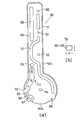
As illustrated in Fig. 14, the upper bracket S0 has
the shape of a flat plate and is constituted by an upper
rectangular portion 50a and a lower circular portion
2 ~ 7
- 13 -
50b. The rectangular portion 50a is provided with three
vertically aligned screw holes 60, 61, 62 through which
screws for attaching the upper brack:et 50 to the seat
back are passed. Further, the rectangular portion 50a
S is provided with a through-hole 63 through which a
turniny shaft 104a of an operating knob 104 (shown in
Fig. 1) of the shoulder-belt adjusting device 6 is
passed so as to be capable of turning.
The circular portion 50b is provided with a hole 64
through which the turning shaft 20 is passed so as to be
capable of turning relative the circular portion.
Further, in order that the seat back 3 may be locked at
any of three reclining angles, three locking holes 65,
66, 67 throuyh which the locking pin 56 is passed are
formed in the circular portion 50b on the circumference
of a circle of a prescribed radius from the center of
the hole 64. In order to lock the seat back 3 at the
folded position, the circular portion 50b is provided
with a lockiny hole 68, located on the same
2~ circumference as the locking holes 65, 66, 67, through
which the locking pin 56 is passed. As shown in (b) of
Fig. 14, each of the locking holes 65, 66, 67, 68 is
elliptical in form, with the ellipse having a minor axis
f and a major axis a. In this case, the minor axis f is
set to have a size that allows the locking pin 56 to be
passed through and slid along the hole with almost no
gap between the pin 56 and the walls of the hole.
Further, the locking holes 65, 66, 67, 68 are so
2~8~7
-- 19 --
arranged that the minor axis f of each hole lies in the
circumferential direction of a circle concentric with
the hole 69 while the major axis ~ of each hole lies in
the d.iarnetric direction of the circl~e concentric with
the hole 6q. The circular portion 50 is further
provided with a longitudinally extending guide slot 69.
When guides 113, 114 of supporting means 102 (shown in
Fig. 25) supporting the belt guide 101 move up and down,
screw portions 113b, 114b of the respective guides 113,
114 are guided by the guide slot 69. The circular
portion 50b is further provided with a hole 117 through
which the upper hook pin 52 is passed and secured.
The portion in which the locking holes 65, 66, 67
for locking the seat back 3 at a prescribed reclining
angle are formed is reinforced by a reinforcing member
70. The upper bracket 50 is formed to have a flange 50c
along the edge of parts of the rectangular portion 50a
and circular portion 50b. The rectangular portion 50a
and circular portion 50b are formed to have reinforcing
ribs 71, 72 by bending. The upper bracket 50 is
reinforced by the reinforcing ribs 71, 72.
As illustrated in Fig. 1, the upper bracket 50 is
secured to the seat back 3 by passing screws through the
screw holes 60, 61, 62 and screwing them into the
mounting holes 38, 39, 40 of the seat back 3. With each
upper bracket 50 thus secured to the seat back 3, play
in the lateral direction is prevented.
As shown in (a) and (b) of Fig. 15, the low~r
2 ~ 7
- 15 -
bracket 51 is formed to have a semicircular portion 51a
on its upper part, while its lowex part is formed to
have a mounting portion Slb fastened to the seat-portion
body 7 by screws. The semicircular portion 51a has a
5 centrally provided circular hole 73 through which the
turning shaft 20 is passed. The sernicircular portion
51a is further provided with a guide slot 74 along an
arc concentric with the hole 73. The upper hook pin 52
is passed through the guide slot 79 and is turnably
0 guided thereby when the seat back 3 is tilted. The
lower bracket 51 includes also a hole 75 through which
the locking pin 56 is slidably passed, and a hole 76
through which the lower hook pin 53 is passed and
secured. In this case, the through-hole 75 is provided
at such a position that the length of a line between the
center of the hole 75 and the center of the hole 73 will
be equal to the radius of the circle, which is centered
on the hole 6~, on which the locking holes 65, 66, 67 of
upper bracket 50 are provided. The upper bracket 50 is
,~ 20 secured to the seat-portion body 7 by screws ~not
shown).
As illustrated in Fig. 1, the turning shaft 20 is
. passed through the hole 73 of the lower bracket Sl,
. which is secured to the seat-portion body 7, and is
supported on the lower bracket S1, and the upper bracket
, 50 secured to the seat back 3 is situated on the outer
side of the lower bracket S1 and is tiltably supported
by passing the tarning sha~t 20 through the hole 6~. In
,
,,,~
' ,
- 16 - 20~47
this case, the upper bracket 50 is prevented from
falling off the turning shaft 20 by a retaining ring 77.
A cover 78 of the turning shaft 20 i'3 attached so as to
cover the turning shaft 20 by fi.tting a projection 78a
of the cover 78 into the through-hole 48 of the seat
back 3 and screwing a screw into the end portion of the
turning shaft 20. The uppex hook pin 52 secured to the
~ upper bracket 50 is passed through the guide slot 74 so
as to extend to inner side of the lower bracket 51 and
1 0 is situated between the turning support portions 18, 19
of the seat-portion body 7. In addition, the torsion
spring 54 is interposed between the upper hook pin S2
and the lower hook pin 53 secured to the lower bracket
51. Thus, the seat back 3 is attached to the seat-
portion body 7 so as to be capable of tilting about the
turning shaft 20.
In this case, one of the locking holes 65, 66, 67,
68 of the upper bracket 50 registers with the through-
hole 75 of the lower bracket 51 depending upon the
: 20 angular position to which the seat back 3 has been
~ tilted. The torsion spring 54 is designed so as to have
; the following spring characteristic: Specifically, the
torsion spring 54 is designed so to assume a free state
when the upper hook pin 52 ~namely one end of the
torsion spring 54) is at a position ~ in Fig. 16. At
this position, therefore, the spring force which the
torsion spring 5~ applies to the seat back 3 is zero.
Further, the torsion spring 54 is so designed that when
~8~47
- 17 -
the seat-portion body 7 is made horizon-tal w.ith the
upper hook pin 52 at position ~, the seat back 3 will
tilt forwardly under its own weight, i.e., in the
direction of a folded-state locking position ~. Owing
to the forward tilting mo-tion of the seat back 3 under
its own weight, the spring force of the torsion spring
54 gradually increases so tha-t the shock of this forward
tilting motion of the seat back 3 is mitigated by this
spring force.
On the other hand, when the seat back 3 is tilted
toward the rear from the ~ position in order to be set
at a desired reclining position, the spring force of the
torsion spring 54 acts upon the seat back 3 in a
direction returning it to the ~ position, and the spring
force grows in conformity with the rearward tilting of
the seat back 3. Accordingly, with the locking pin 56
inserted into any one of the locking holes 65, 66, 67 to
set the seat back 3 at a prescribed reclining angle, the
spring force of the torsion spring 54 that restores the
upper hook pin S2 to the ~ position becomes
comparatively large. As a result of this spring force,
the seat back 3 is biased in such a manner that the edge
of the particular one of the locking holes 65, 66, 67 on
the minor-axis side thereof comes into abutting contact
with the locking pin 56 at all times. As a result,
angular play of the seat back 3 in the back-and-forth
direction in which the seat back is tilted is prevented.
Further, when reclinlng of the seat back 3 at~:empts
- 18 - 2~ 7
to be set in a half-latched state in which the locking
pi.n 56 is not completely inserted into any of the
locking holes 65, 66, 67, the seat back 3 is tilted in
the forward direction by the enlarged spring force of
S the torsion spring 54. Accordingly, half-latching of
the seat back 3 when reclining o-f the seat back is being
set is prevented in reliable fashion.
Thus, the torsion spring 54 is designed so as to
have a shock-absorber function which mitigates the shock
due to forward tilting motion of the seat back 3 under
its own weight, a play-preventing function for
preventing play when the seat back 3 is reclined, and a
half-latching preventing function for preventing ha~f-
latching of the seat back 3 when reclining of the latter
is set.
As shown in Fig. 17, the operating lever 55
includes an operating portion 55a arranged in the recess
12 of the seat-portion body 17 for actuating the
operating lever 55, a penetration portion 55b which is
passed through the guide hole 13, a support portion 55c
for slidably supporting the operating lever 55 on the
seat-portion body 17, and a connection portion 55d to
which the operating-force transmitting link 59 is
connected. The connectin~ portion 55d is provided with
a hole 55e for fixing the link 59 tha~ has been passed
through the hole 55e.
As shown in Fig. 18, the locking pin 56 is formed
from a round bar, one erld of which i.s forrned to have a
- lg- ~ 47
cam follower 56a bent at a righ-t angle. The cam
follower 56a is fitted lnto cam slots 80, 81 (shown in
Fig. 19) of the cam plate 57 and is moved by movement of
the cam plate 57 while being guided by the cam slots 80,
81. The other end of the locking pin 56 is formed to
have a locking portion 56b. Owing to movement of the
locking pin 56 while it is being guided by the cam slots
80, 81, the locking portion 56b is passed through one of
the locking holes 65, 66, 67, 68 of the upper bracket 50
and the through-hole 75 of the lower bracket 51 so as to
lock the upper bracket 50 and the lower bracket 51. In
this case, the other end of the locking pin:56 is
provided with a chamfer A. The locking portion 56b is
passed through the locking holes 65, 66, 67, 68 and the
through-hole 75 more easily by virtue of the chamfer A.
As illustrated in Fig. 19, the cam plate 57 is
formed substantially as a flat plate having a centrally
provided comparatively large hole 79 extending in the
longitudinal direction. In cam plate 57 as it appears
in Fig. 19, the upper edge is formed to have the pair of
cam slots 80, 81, which diverge from each other from the
top down, into which the cam follower 56a of the locking
pin 56 is inserted. The lower end of the cam plate 57
is provided with a hole 82 to which one end of the
operating-force transmitting link 59 is connected, and
with a hole 83 to which one end of the biasing spring 97
(shown in Fig. 2), which biases the cam plate 57 upward
at all times as seen in Fig. 19, is connected. The left
- 20 - ~ 47
and right side edges and the upper edge of -the cam plate
57 are formed to have a flange 57a. In paxticular, the
flange portions of flange 57a that are formed on the
right and left side edges of the cam plate 57 serve as
guide portions 57b which come into abutting contact with
a guiding surface 58d ~shown in Fig. 20) of the case 58
so as to guide the cam plate 57 along this guiding
surface.
As illustrated in (a) through (c) in Fig. 20, the
case 58 is formed as a flat plate and has a main body
58a one side surface of which is provided with a pair of
parallel upstanding side walls 58b, 58c extending in the
longitudinal direction. As indicated by the phantom
lines in (c) of Fig. 20, the cam plate 57 is disposed so
as to be movable in the longitudinal direction of the
case within a space delimited by the main body 58a and
the two side walls 58b, 58c. In this case, the cam
plate 57 moves while being guided along the guiding
surface 58d of the main body 58a owing the fact that the
guide portions 57b abut against the gulding surface 58d,
and while being guided along the two side walls 58, 58c.
Further, the one side surface of the main body 58a is
provided with an upstanding projection 58e that mates
with a projection 91 (shown in Fig. 21) on the pin cover
84.
The two side walls 58b, 58c are each provided with
a locking-pin through-hole 85 through which the locking
pin 56 is capable of being inserted. A pair of ~uides
- 21 - 2~8~47
86, 87 which guide the locking pin 56 are provided in an
upstanding a-ttitude, so as to correspond to the locking-
pln through holes 85, between the two side walls 58b,
58c on the one side face of the main body 58a. Guiding
S supports 88 for the locking pin 56, which supports have
a semicircular recess the diameter of which is the same
as that of the locking-pin through-hole 85, are provided
on the outer side of the side walls 58b, 58c of the main
body 58a. Mounting portions 89 to which the pin cover
0 84 is attached are provided on both sides of each of the
guiding supports 88. Further, the other side surface of
the main body 58a is provided with a mounting portion 90
for mounting the case 58 on the seat-portion body 7.
As illustrated in Fig. 21, the pin cover 84 is
provided at the center of its main body 84a with the
upstanding projection 91 formed to have a circular hole
92. The circular hole 92 mates with the projection 58e
of the case 58, as mentioned above, whereby the case 58
and the pin cover 89 are positioned. The main body 84a
is provided with a pair of guide slots 93, 94 in each of
which is inserted the tip of the cam follower 56a of the
locking pin 56 passed through the cam slots 80, 81. The
cam follower S6a is capable of moving along the guide
slots 93, 94.
Further, the left and right edges of the main body
84 are provided with guiding supports 9S for the locking
pin 56, which supports have a semicircular recess the
diameter of which is the same as that of the loc~ing-pin
- 22 ~0~47
through-holes 85. The recess of each guiding support 95
cooperates with the recess of the guiding support 88 in
the case 58 so as ~o form a locking-p:in through-hole the
diameter of which is equal to that of the locking-pin
through-hole 85 of case 58.
Accordingly, the locking pin 56 is guided by the
guide slots 93, 94, the pair of guides 86, 87, the
locking-pin through-hole 85 and the locking-pin through-
hole formed by the recess of the guiding support 95 and
1 0 the recess of the guiding support 88. As a result,
movement of the locking pin 56 is reliable and smooth.
Mounting portions 96 are provided on both sides of
each guiding support 95. By attaching the mounting
portions 96 to the mounting portions 89 of the case 58,
the pin cover 84 is attached to the case 58.
With the cam plate 57 and pin cover 84 installed
in the case 58, the biasing spring 97 is compressed
between the projection 92 of the pin cover 89 and the
hole 83 of the cam plate 57, as depicted in Fig. 2. The
biasing spring 97 constantly urges the cam plate 57
upward and diagonally to the left in Fig. 2 with respect
to the case 58. Accordingly, in the ordinary state, the
locking pin 56 is situated at the lowermost end of the
diverging cam holes 80, 81 in Fig. l9(a).
As illustrated in Fig. 2, the operating-force
transmitting link 59 has one end thereof connected to
the hole 55e of the connecting portion 55d of operating
lever 55. The other end of the link 59 is connected to
- 23 - 2~4~7
the hole 82 of the cam plate 57. The operating-force
transmitting lever 59 is capable of being formed from a
conventional common Eorce--transmitting link, such as a
rod, an inner cable, an outer cable or a combination
5 thereof, and an appropriate location along the link 59
is supported on the seat-por-tion body 7.
In the seat-back tilting control device 4 thus
construc-ted, the cam follower 56a of the locking pin 56
ordinarily is set at the lowermost end of the cam slots
80, 81 by the biasing spring 97, as described above, and
the locking pin 56 is projecting to the maximum degree.
With the locking pin 56 in this state, as shown in Fig.
22, the locking portion 56b is fitted into any one of
the locking holes 65, 66, 67, 68 and the through-hole
75. The locking pin 56 therefore is in the locking
position~ As a result, the seat back 3 is set at a
prescribed reclining angle or in the folded position.
When the cam plate 57 is moved downward in Fig. 22 by
pulling the operating lever 5 forward, the cam follower
56a is guided by the cam slot 80, and therefore the
locking pin 56 moves to the right. When the cam
follower 56a is situated at the uppermost end of the cam
slot 80, as indicated by the phantom lines, the locking
portion 56b exits completely from one of the locking
holes 65, 66, 67, 68 and from the through-hole 75,
whereby the locking pin 56 assumes the unlocking
position. As a result, the seat back 3 is free to tilt.
Thus, in the present embodiment, the seat-back tilting
- 24 ~ 7
control device 4 functi.ons as both reclined-st~te
loeking means for locking the seat baek 3 at a
prede-termined reclining angle and folded-state locking
means for locking the seat baek 3 in the folded
position.
The infant seat belt deviee 5 ineludes lef-t and
right shoulder belts Sa, a chest-contact pad 5b
eonneeted to the shoulder belts Sa, a tongue Se attaehed
to the lower end of the chest-contact pad Sb, the buekle
0 5d with which the tongue Sc locks, and a retractor Se
for taking up a webbing, whieh unites the left and right
shoulder belLs 5a into a single body, through the back
of the seat back 3. The infant seat belt deviee S is
substantially identieal with that of the prior art.
As depicted in Figs. 1 and 2, a cover seat 98 is
supported on the turning shaft 20, which tiltably
supports the seat baek 3 relative to the seat portion 2,
so as to be capable of tilting between the position
indieated by the solid line and the position indieated
by the phantom line in Fig. 2, the eover seat 98 being
situated between the left and right lower braekets 51.
As illustrated in Fig. 23, the eover seat 98 has a
eurving main body 98a the upper surfaee of whieh defines
a seat surfaee 98b for seating an infant. The lower
surfaee of the main body 98a is provided with a
predetermined number of ribs 98e. The ribs 98e, whieh
are formed to be identieal in shape, have a reetangular
first projection 98d and a triangular seeond projeet.ion
- 25 - 20~4~7
98e. The upper end of the cover seat 98 is provided
with a hole 98h into which the turning .shaft is loosely
fitted.
The cover seat 98 is formed in such a manner that
when it is at the position indicated by the solid line
in Fig. 2, it will cover the second recess of the seat-
portion body 7 and cooperate with the seat surface 7a at
the forward part of the seat-portion body 7 and a seat-
back surface 31a of the seat back portion 31, which
0 constltutes the seat back 3, to render continuous the
seat surface of the protective seat 1 and the surface of
the seat back. As a result, the infant can be seated
safely and reliably. In this case, as illustrated in
Fig. 2, a tip 98f of the first projection 98d comes into
abutting contact with one inclined surface of the V-
shaped second recess 14, and an oblique end 9~g of the
second projection 98e comes into abutting contact with
the other-inclined surface of the second recess 14. As
a result, the weight of the seated infant is reliably
supported on the seat-portion body 7 via the ribs 98c.
When the cover seat 98 is at the position indicated
by the phantom line in Fig. 2, on the other hand, it
opens the second recess 14 of the seat-portion bod~ 7.
As result, when the protective seat 1 is attached to and
detached from a vehicle seat, as shown in Fig. 24, the
operation for fastening and unfastening of the tongue
123 and buckle 129 of the seat belt device, which is
installed at the vehicl.e seat and situated in the second
- 26 - ~0~4~7
recess 14, can be performed easily from above the front
of the protective seat 1 (i.e., from the direction of
arrow B). In particular, when it is difficult to secure
the protective seat 1 to the vehicle seat from the sides
of the vehicle seat whose width is only slightly larger
than the width of the protective seal 1, as in a vehicle
seat both sides of which have wings or arm rests, the
operation for attaching and detaching the protective
seat is greatly simplified.
As illustrated in Figs. l and 2, the shoulder-belt
adjusting device 6 includes the belt guide 101 for
guiding the shoulder belts of the infant seat belt in
such a manner that the position of the shoulder belts
can be adjusted up or down, the supporting means 102 for
supporting the belt guide 101, the vertically extending
screw shaft 103 for moving the supporting means 102 up
and down, the operating knob 104 turnably attached to
one of the left and right side walls 32, 33 (the left
side wall 33 in the example illustrated) of the seat
back 3, and the torque link 105 which connects the
operating knob 104 and the screw shaft 103 while
producing a right-angle change in direction, and which
transrnits the rotational torque of the operating knob
104 to the screw shaft 103. The torque link lOS is
capable of being formed of a resilient torque link used
generally in the prior art.
: As depicted in Fig. 25, the belt guide 101 has a
main body lOla comprising an elongated flat plate having
- 27 - 2~4~7
the shape of a parallelogram. The main body lOla has a
slot 106, which is provided substantially at the middle
thereof, th.rough which the shoulder belt of the infant
seat belt is slidably passed, and is :integrally formed
to-have a cylindrical portion 107 extending from one
side of the main body lO1 to the other side thereof.
Furthermore, one end of the cylindrical portion 103 is
formed to have a flange 109. The other end of the
cylindrical portion la7 is provided with a grip portion
110 which grips a cylindrical member 109 of the
supporting means 102.
As indicated by the phantom line in Fig. 3, the
seat cover 111 is attached to the seat back 3 via a
cushion 112. The seat cover 111 and the cushion 112 are
- lS formed to have holes of the same shape as the guide
slots 34, 35 at positions corresponding to the guide
slots 34, 35 of the seat back 3. The cylindrical
portion 107 between the main body lOla and the flange
108 slidably penetrates these holes in the cover 111 and
cushion 112. Accordingly, the cover 111 and the cushion
112 are situated between the main body lOla and the
flange 108.
The main body 101a on the side of the grip portion
110 is in abutting contact with the seat back 31 of -the
seat back, as shown in Fig. 3, and the belt guide 101 is
capable of sliding along the main body lOla. Further,
the cylindrical portion 107 between the main body lOla
and the grip portion 110 is passed through the guide
- 28 - ~ ~ g
slots 34, 35 and is capable of sliding while being
guided by the guide slots 34, 35. Accordingly, the belt
guide 101 is capable of moving between an upper-limit
position (the position at which the slot 106 is
indicated by the solid line) C at which the cylindrical
portion 107 abuts against the upper end of the guide
slots 34,-35, and a lower-limit position (the position
at which the slot 106 is indicated by the phantom line)
D at which the cylindrical portion 107 abuts against the
lower end of the guide slots 34, 35.
In this case, the main body lOla is designed to
have such a size that the guide slots 34, 35 and the
holes in the cover 111 and cushion 112 can be closed
even when the cylindrical portion 107 of the belt guide
101 is situated at a position between the upper-limit
position and the lower-limit position. The external
shape of the flange 108 is formed to be larger than that
of the guide slots 34, 35, and therefore the cover 111
and cushion 112 may be easily detached from between the
flange 108 and main body lOla.
The supporting means 102 includes the cylindrical
member 109 and guides 113, 114 fixedly secured to the
left and right ends of the cylindrical member 109, as
illustrated in Fig. 26. The central part of the
cylindrical member 109 is formed to have female threads
that are threadedly engaged by the screw shaft 103, and
holes lO9b, lO9c, through which bolts for securing the
grip portion 110 of the belt guide 101 are passed, are
- 29 - 2~8~7
provided in the cylindrical member on both sides of the
female threads lOga. The guides 113, 114 respectively
comprise disk-shaped guide portions 113a, 114a and screw
portions 113b, 114b upstanding from the centers of the
guides. The guides 113, 114 are screwed respectively
into closing members 115, 116 secured in the two ends of
the cylindrical member 109 so as to form prescribed gaps
h, whereby the guides 113, 114 are fixed to the
cylindrical member 109.
The screw portions 113b, 114b of the respective
guides 113, 114 are passed through the guide slots 69 of
the upper brackets 50 secured to the left and right side
walls of the seat back 3, and t.he upper brackets 50 are
situated in the gaps h so that the supporting means 102
lS is attached so as to be movable up and down while being
guided by the guide slot 69. A laterally directed
force, a longitudinally directed force and moments about
these directions acting upon the cylindrical portion 109
are supported by the upper brackets 50.
As shown in Figs. 1 and 2, the screw shaft 103 is
threadedly engaged with the female threads lO9a of the
cylindrical member 109, and the upper and lower ends of
the screw shaft 103 are supported respectively by the
brackets 36, 37 of the seat back 3. With regard to the
bracket 36 on the upper side in this case, the upper end
of the screw shaft 103 is supported so as to be capable
solely of rotation in the free state in the thrust
direction. Wi.th regard to the bracket on the lower
- 30 - 2~4~7
side, the lower end of the screw shaft 103 is suppor-ted
so as to be capable of rotation in the supported state
in the thrust direction. Accordingly, the up-and-down
force which acts upon the cylindrical member 109 is
5 supported by the bracket 37 on the lower side via the
screw shaft 103 and is not supported by the bracket 36
on the upper side. As a result, though it is necessary
for the bracket 37 on the lower side to be made
comparatively large for reasons of strength, it will
suffice if the bracket 36 on the upper side is
- comparatively small. This means that although the seat
back 3 is tilted back when the protective seat 1 is in
use, as shown in Fig. 2, the amount of projection of the
protective seat 1 to the rear is small owing to the fact
~15 that the upper bracket 36 is small. Accordin~ly, when
the protective seat is secured to the seat of the
vehicle, the seat 1 is prevented from being secured to
far forward relative to the vehicle seat. By virtue of
this feature, the body of the infant can be kept a
greater distance away from the parts of the vehicle in
front of the seat, and the protective seat 1 can be
secured to the vehicle seat more stably and reliably.
As shown in Fig. 1, one end of the torque link 105
is connected to the lower end of the screw shaft 103 in
such a manner that it is incapable of rotating relative
to the screw shaft 103. The torque link 105 is bent at
right angles from the vertical direction and extends to
the left, and the other end thereof is rotatably
- 31 - 20~ 7
supported on the bracket 44 secured to the seat back 3.
This end of the torque link 105 serves as a connecting
portion lOSa formed to have an angular cross section.
~The connecting portion 105a is directed leftward in
reliable fashion by the bracket 44.
The operating knob 104 is turnably attached to the
left side wall 32 of the seat back 3 at a position
opposing the connecting por-tion 105a of the torque link
105. In this case, the operating knob 104 is capable of
being attached and detached to and from the left side
wall 32 by a force greater than a prescribed value. The
end portion of the turning shaft 104a of the operating
knob 104 is provided with a hole 104b the sectional
shape of which is similar to but somewhat larger than
the sectional shape of the connecting portion 105a of
torque link 105. Accordingly, when the operating knob
104 is inserted into and attached to the left side wall
32, the connecting portion 105a is fitted into the hole
109b, as a result of which the turning shaft 104a and
connecting portion 105a are connected to make only
rotation impossible. In this case, the turning shaft
lOqa is guided by a guide 118, and therefore the turning
shaft 104a and connecting portion 105a are capable of
being connected easily and reliably.
As shown in Fig. 1, the supporting means 102, screw
shaft 103 and torque link 105 are covered by the cover
126.
In the case of this embodiment, the operating knob
- 32 - 2~8~7
109 is disposed on ~he left side wall 32. By adopting
this arrangement, the amount of rearward projection of
the seat back 3 is reduced in comparison with a case in
which the operating knob 32 is provided on the upper
portion of the seat back 3. Accordingly, when the
infant-restraining protective seat l i.s secured to a
vehicle seat, the protective seat 1 is prevented from
being secured too far forward relative to the vehicle
seat, just as described above. Though the operating
0 knob 104 is disposed on the left side wall 32 in this
embodiment, the operating knob 104 can be disposed on
the right side wall 33 if desired.
When the operating knob 109 is turned in the
shoulder-belt adjusting device 6 thus constructed, the
rotational torque is transmitted to the screw shaft 103
via the torque link 105, whereby the screw shaft 103 is
turned. Turning the screw shaft 103 in one direction
lowers the belt guide 101, whereas turning the screw
shaft 103 in the other direction raises the belt guide
101. Thus, the position of the shoulder belts of the
infant seat belt device can be continuously adjusted up
and down.
In accordance with the infant-restraining
protective seat according to the first aspect of the
present invention, as evident from the foregoing
description, the seat portion for seating the infant and
the seat back for supporting the back of the seated
infant are capable of being folded. When the infant-
- 33 - 2~8~7
restraining protective seat is not in use, the
protective seat can be reduced in size by folding the
seat portion and the seat back. Accordingly, the
protective seat can be carried about and set up on the
5 seat of a vehicle much more easily. In addition, only a
small amount of space is necessary for storage.
Further, after the seat back has been tilted
backward in order to set it at the prescribed reclining
position, the locking pin is inserted into the locking
hole, whereby the seat back can be locked at the
prescribed reclining angle. Furthermore, since the
locking hole is formed as an elongated hole whose minor
axis lies in the tilting direction of the seat back,
play of the seat back in the tilting direction can be
suppressed.
As many apparently widely different embodiments of
the present invention can be made without departing from
the spirit- and scope thereof, it is to be understood
that the invention is no-t limited to the specific
em~odiments thereof except as defined in the appended
clalms.
- 3~ ~ 20~ 7
WHAT IS CLAIMED IS:
1. An infant-restraining protective seat comprising:
a seat portion for seating an infant;
a seat back for supporting the back of the seated
infant;
infant restraining means such as an infant seat
belt device for restraining and protecting the seated
infant;
said seat back being tiltably attached to said seat
0 portion, and said seat portion and seat back being
adapted so as to be foldable; and
locking means for locking said seat back at a
prescribed backward tilt angle;
said locking means having a through-hole provided
in said seat portion, a locking hole provided in said
seat back so as to correspond to the prescribed backward
tilt angle, and a locking pin that is passed through
said through-hole and said locking hole, said locking
hole being formed as an elongated hole such as of
elliptical shape having a minor axis in the tilting
direction of said seat back and a major axis in a
diametric direction.
.
BARRIGAR ~ OYEN
81 Metcalfe St., 7th ~loor
Ottaw~, OntQ~io
KIP 6K7
A~ent~ for the Applicant