Sélection de la langue

Search

Sommaire du brevet 2084939 

Énoncé de désistement de responsabilité concernant l'information provenant de tiers

Une partie des informations de ce site Web a été fournie par des sources externes. Le gouvernement du Canada n'assume aucune responsabilité concernant la précision, l'actualité ou la fiabilité des informations fournies par les sources externes. Les utilisateurs qui désirent employer cette information devraient consulter directement la source des informations. Le contenu fourni par les sources externes n'est pas assujetti aux exigences sur les langues officielles, la protection des renseignements personnels et l'accessibilité.

Disponibilité de l'Abrégé et des Revendications

L'apparition de différences dans le texte et l'image des Revendications et de l'Abrégé dépend du moment auquel le document est publié. Les textes des Revendications et de l'Abrégé sont affichés :

  • lorsque la demande peut être examinée par le public;
  • lorsque le brevet est émis (délivrance).
(12) Demande de brevet: (11) CA 2084939
(54) Titre français: BRAS OSCILLANT TRANSVERSAL SUPERIEUR POUR SUSPENSION DE VEHICULE
(54) Titre anglais: UPPER CONTROL ARM FOR VEHICLE SUSPENSION SYSTEM
Statut: Réputée abandonnée et au-delà du délai pour le rétablissement - en attente de la réponse à l’avis de communication rejetée
Données bibliographiques
(51) Classification internationale des brevets (CIB):
  • B60G 07/00 (2006.01)
(72) Inventeurs :
  • DELBEKE, ROBERT G. (Etats-Unis d'Amérique)
  • RICHART, LELAND M. (Etats-Unis d'Amérique)
(73) Titulaires :
  • MASCO INDUSTRIES, INC.
(71) Demandeurs :
  • MASCO INDUSTRIES, INC. (Etats-Unis d'Amérique)
(74) Agent: SMART & BIGGAR LP
(74) Co-agent:
(45) Délivré:
(22) Date de dépôt: 1992-12-09
(41) Mise à la disponibilité du public: 1993-06-11
Requête d'examen: 1993-01-29
Licence disponible: S.O.
Cédé au domaine public: S.O.
(25) Langue des documents déposés: Anglais

Traité de coopération en matière de brevets (PCT): Non

(30) Données de priorité de la demande:
Numéro de la demande Pays / territoire Date
07/805,295 (Etats-Unis d'Amérique) 1991-12-10

Abrégés

Abrégé anglais


ABSTRACT OF THE DISCLOSURE
An upper control arm for a vehicle suspension system having a
modulus section of hollow construction for reduced weight. The
modulus section of the control arm is of a stamped and welded
construction thereby eliminating material weight while reducing the
cost of manufacturing. The modulus section has a substantially
triangular configuration with a reinforced rim flange along the
high compression stress area of the control arm elbow. The
reinforced rim flange improves the strength of the control arm
without sacrificing the weight reduction provided by the hollow
construction.

Revendications

Note : Les revendications sont présentées dans la langue officielle dans laquelle elles ont été soumises.


CLAIMS
1. A control arm for a vehicle suspension system adapted to
be connected to a ball joint assembly and a pivot bar assembly,
said control arm comprising:
an integral body having a substantially U-shaped configuration
with means for receiving the ball joint assembly at the apex of
said body and means for receiving the pivot bar assembly at the
ends of said body;
said integral body having modulus sections along each arm,
said modulus sections having a hollow, substantially triangular
cross-sectional configuration.
2. The control arm as defined in claim 1 wherein said
modulus sections include an upper seam formed along the top apex of
said triangular modulus section.
3. The control arm as defined in claim 2 wherein said upper
seam is welded to join two walls of said triangular modulus section
Forming said top apex.
4. The control arm as defined in claim 3 wherein said
triangular modulus sections include a reinforcement rim flange for
improved rigidity along said modulus sections.
5. The control arm as defined in claim 4 wherein said rim
flange is formed along said upper seam of said modulus sections,
said rim flange being an extension of said joined walls forming
said top apex, said flanges of said joined walls extending
outwardly beyond said welded seam.
6. A control arm for a vehicle suspension system adapted to
be connected to a ball joint assembly and a pivot bar assembly,
said control arm comprising:

an integral body having a substantially U-shaped configuration
with means for receiving the ball joint assembly at the apex of
said body and means for receiving the pivot bar assembly at the
ends of said body;
said integral body having a modulus sections along each arm,
said modulus sections having a hollow, substantially triangular
cross-sectional configuration with an upper seam along the top apex
of said triangular modulus sections formed by joining two walls of
said triangular modulus section.
7. The control arm as defined in claim 6 and further
comprising a reinforcement rim flange for improved rigidity along
said modulus sections, said rim flange formed along said upper arm.
8. The control arm as defined in claim 7 wherein said rim
flange is an extension of said joined walls of said triangular
modulus section, said rim flange extending from said joined walls
outwardly of said upper seam.
9. The control arm in claim 8 wherein said upper seam is
formed by welding said two walls of said triangular modulus
section.
10. A control arm for a vehicle suspension system adapted to
be connected to a ball joint assembly and a pivot bar assembly,
said control arm comprising:
an integral body having a substantially U-shaped configuration
with means for receiving the ball joint assembly at the apex of
said body and means for receiving the pivot bar assembly at the
ends of said body;
said integral body having modular sections along each arm,
said modulus sections having a hollow, substantially triangular
cross-sectional configuration, with an upper seam along the top
apex of said triangular modulus sections formed by joining two
walls of said triangular modulus section, said upper seam including

a reinforcement rim flange formed as an extension of said joined
walls.
11. The control arm as defined in claim 10 wherein said
joined walls of said triangular modulus section are welded, said
joined walls extending outwardly from said weld to form said
reinforcement rim flange.
12. The control arm as defined in claim 11 wherein said
triangular modulus sections of said control arm are of an integral,
one-piece stamped construction with opposing edges joined to form
said triangular cross-sectional configuration.

Description

Note : Les descriptions sont présentées dans la langue officielle dans laquelle elles ont été soumises.


9 3 9
UPPER CQ~ L ARM FO~
VE~IICI,E Sl S~ION SYSTE~
Backqro~lnd Of The Invention
I. Field o~ the~ ntion
This invention relates to an uE~per control arrn for a vehicle
suspension s~ste~ and, in particular, to a control arm haviny a
modulus section of hollow construction with an enlarged rim ~lange
for rein~orcement of high load stress areas of the control arm.
II. Description o~ the Prior Art
Upper control arms are routinely incorporated inko the
suspension systems of truck and passenger vehicles. The typical
control arm is generally U-shaped with a ball joint assembly at the
apex of the control arm and pivot bar bushings at the ends o~ the
arm ~or mounting the control arm to a pivot bar assembly. In the
past, the modulus sections between the bushings and the ball joint
have been solid sections o~ cast iron or cast aluminum~ It was
believed that the traditional cast metal sections were necessary to
maintain the integrity o~ the control arm under the stresses o~ the
suspension system. Mora recently, the modulus section has been
constructed of a steel ~orging of wire frame design. Alkhough
these control arm constructions were strong enough to withstand the
stress loads they also were very heavy. In today's vehicle market
every aspect of a vehicle i5 examined for weight reduction.
Recent proposals for reducing the weight of the suspension
system include a hollow, two-piece control arm. The square hollow
bar section comprises a pair of U-shaped components nested together
and double seam welded. Thus, the control arm has double side
walls with single upper and lower walls. Although strong and
lightweight, the double side walls are not located at the
compressive stress areas o~ the arm where additional strenyth is
required. Moreover, the double seam construction requires precise
welding over a curving contour which has not been easy to
accommoda~e. Nevertheless, substantial weight reduction over -the
,, ,, , :,,, ,. :
. ,

solid cros~-section o~ the prior known control arm~ has been
accomplished.
ummary Of The Present Xnvention
The present invention overcomes the disadvantages Oe ~he prior
known control arms for vehicle suspension systems by incorporating
a modulus section of hollow construction having a substantially
triangular configuration in order to distribute the compressive
stress loads associated with the su~pension system. An enlarged
rim flanye at the joint apex of the stamped triangular construction
provides improved rein~orcement at the high compression stress
areas of modulus section.
Typical of control arms, the present invention has a
substantially U-shaped con~iguration with a ball joint assembly at
the apex and pivot bar bushings at the ends of the control arm.
However, the control arm of the present invention includes a
modulus section having a substantially triangular hollow cross-
section which reduces the overall weight o~ the control arm while
maintaining strength in key stress araas of the elbow sections.
The hollow triangular sections are formed through a stamping
procPss wherein the upper apex of the modulus section incorporates
a seam weld to ~orm the triangular cross-section. For increased
stiffening and reinforcement, an enlarged rim flange is ~ormed
along the welded apex seam. This rim flange along the high
compression stress ares of the control arm elbow eliminates stress
failures along this area and permits double plate FEA modeling
resulting in additional load balancing capabilities.
Other objects, features and advantages of the invention will
be apparent from the following detailed description taken in
connection with the accompanying drawings.
Brief Descri~tion of the Drawinqs
The present invention will be more fully understood by
reference to the following detailed de~cription of a preferred
embodiment of the present invention when read in conjunction with
.
,
~, .

2 ~ 3 ~
the accompanying drawiny, in which like reference characters re~er
to like parts throughout the views and in which:
FIGURE 1 is an elevated perspective view of a upper control
arm for a vehicle suspension system embodying the present
invention; and
FIGURE 2 is a cross-sectional view of the control arm taken
along lines 2-2 of Fig. 1.
L~ 5~ç~,~sl~_Q~ ~ Pre~e~xed
~bodiment Of The Present Invention
Referring ~to Figures 1 and 2, there is shown elevational and
cross-sectional views of a control arm 10 embodyiny -the principles
of the present invention. The control arm lO is preferably an
upper con-trol arm forming a part o~ a suspension system of a
vehicle. As is typical of such components, the control arm 10 has
a substantially l1-shaped configuration with bushing apertures 1~
formed at the ends of the ar~s 14 and a ball joint receptacle 16
formed at the apex 18 of the control arm 10. The ball joint
receptacle 16 is adapted to cooperate with a ball joint assembly
(not shown) and may include a ball joint housing integrally formed
with the control arm 10. Typical modern control arms 10
incorporate a separate ball joint housing which is inserted into
the apex 18 of the control arm 10. The bushing apertures 12 are
designed to retain pipe bushings (not shown) for mating engagement
with a pivot bar assembly forming a portion of the vehicle
suspension system. The pivot bar typically extends through both
bushinq apertures 12 allowing the control arm 10 to pivot about the
assembly in response to road conditions affecting the vehicle
suspension system.
The control arm 10 of the present invention is ~ormed of an
integral metal stamping to ensure the required structural stren(~th
for the suspension system. However, unlike the prior known control
arms which incorporate a solid construction, the present invention
comprises hollow modulus sections 20 for weight reduction. The
control arm 10 includes modulus sections ~0 along each arm 14
,
.
'. ':~
~,
'; ~

~0~3.~
bet~teen the apex 18 and the bushing apertur~s 12. These ~lodulus
sections 20 are subject to extreme compressLon and tension loads
and there~ore must have sufficient structural strength to~ithstand
such loads. In order to maintain -the struc~ural strength while
providing substantial weight r~duction, the modulus sections 20 of
the control arm 10 oE the present invention are provided with a
hollow, substantially triangular cross-sectional configuration as
best shown in Fiq. 2. It has been found that this trianyular
configuration provides improved strength against the loads while
also providing a uniEorm weld line ov~er the contours of the modulus
sections 20 facilitating programmable welding o~ the seam 22 along
the modulus sections 20.
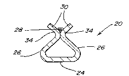
The modulus sections 20 oE the control arm 10 include a bottom
wall 24 and a pair of side walls 26 whlch are ben-t into mutual
contact to form the trianyular configuration. An upper seam 28 is
formed at the contact point which is welded to maintain tlle
integrity of the modulus sections 20. Extending outwardly from the
welded upper seam 28 is a reinforcement rim flange 30. The rim
flange 30 improves the structural strength of the modulus sections
20 particularly the high compression load areas 32 at the bends in
the control arm 10. ~he rim flange 30 is formed by integral
extensions 34 of the side walls 26 formed perpendicular to the
particular side wall 26 from which it extends. The rim flange 30
has a stiffening effect on the hollow modulus sections 20 of the
control arm 10. Thus, the hollow, substantially triangular modulus
sections 20 provide a substantial reduction in weight and cost o~
manufacturing without sacrificing the structural strength necessary
to maintain the integrity of the control arms 10 of the vehicle
suspension system.
The foregoing detailed description has been given ~or
clearness of understanding only and no unnecessary limitations
should be understood therefrom as some modifications will be
obvious to those skilled in the art without departing ~rom the
scope and spirit of the appended claims.
What is claimed is:
` , :,

Dessin représentatif
Une figure unique qui représente un dessin illustrant l'invention.
États administratifs

2024-08-01 : Dans le cadre de la transition vers les Brevets de nouvelle génération (BNG), la base de données sur les brevets canadiens (BDBC) contient désormais un Historique d'événement plus détaillé, qui reproduit le Journal des événements de notre nouvelle solution interne.

Veuillez noter que les événements débutant par « Inactive : » se réfèrent à des événements qui ne sont plus utilisés dans notre nouvelle solution interne.

Pour une meilleure compréhension de l'état de la demande ou brevet qui figure sur cette page, la rubrique Mise en garde , et les descriptions de Brevet , Historique d'événement , Taxes périodiques et Historique des paiements devraient être consultées.

Historique d'événement

Description Date
Le délai pour l'annulation est expiré 1995-06-11
Demande non rétablie avant l'échéance 1995-06-11
Réputée abandonnée - omission de répondre à un avis sur les taxes pour le maintien en état 1994-12-09
Inactive : Demande ad hoc documentée 1994-12-09
Demande publiée (accessible au public) 1993-06-11
Exigences pour une requête d'examen - jugée conforme 1993-01-29
Toutes les exigences pour l'examen - jugée conforme 1993-01-29

Historique d'abandonnement

Date d'abandonnement Raison Date de rétablissement
1994-12-09
Titulaires au dossier

Les titulaires actuels et antérieures au dossier sont affichés en ordre alphabétique.

Titulaires actuels au dossier
MASCO INDUSTRIES, INC.
Titulaires antérieures au dossier
LELAND M. RICHART
ROBERT G. DELBEKE
Les propriétaires antérieurs qui ne figurent pas dans la liste des « Propriétaires au dossier » apparaîtront dans d'autres documents au dossier.
Documents

Pour visionner les fichiers sélectionnés, entrer le code reCAPTCHA :


Pour visualiser une image, cliquer sur un lien dans la colonne description du document. Pour télécharger l'image (les images), cliquer l'une ou plusieurs cases à cocher dans la première colonne et ensuite cliquer sur le bouton "Télécharger sélection en format PDF (archive Zip)" ou le bouton "Télécharger sélection (en un fichier PDF fusionné)".

Liste des documents de brevet publiés et non publiés sur la BDBC .

Si vous avez des difficultés à accéder au contenu, veuillez communiquer avec le Centre de services à la clientèle au 1-866-997-1936, ou envoyer un courriel au Centre de service à la clientèle de l'OPIC.


Description du
Document 
Date
(aaaa-mm-jj) 
Nombre de pages   Taille de l'image (Ko) 
Dessins 1993-06-10 1 26
Revendications 1993-06-10 3 96
Abrégé 1993-06-10 1 17
Description 1993-06-10 4 198
Dessin représentatif 1999-03-21 1 4
Courtoisie - Lettre du bureau 1993-11-18 1 41
Correspondance de la poursuite 1993-01-28 1 26