Note : Les descriptions sont présentées dans la langue officielle dans laquelle elles ont été soumises.
o 2085288
INSERT HOLDER WITH SEALABLE OPENING
Technical Field and Background of the Invention
This invention relates to an insert holder of the type used to
enclose small photographs, documents such as drivers licenses,
identification cards and the like. Many insert holders are known
in the prior art. Those cf which the applicant is aware can be
categorized as follows: -
1. a single transparent or translucent plastic sheet whichis folded to receive the insert, after which the folded sheet is
laminated to seal the three open sides and laminate the sheets to
the opposed faces of the insert;
2. two sheets which are sealed on three sides with a
permanently open fourth side so that the insert can be inserted and
removed repeatedly.
3. two sheets which are sealed on three sides with a open
fourth side so that the insert can be inserted. Then the sheet is
laminated to laminate the sheets to the opposed faces of the
insert;
4. two sheets which are sealed on three sides with a
permanently open fourth side so that the insert can be inserted and
removed repeatedly. A number of the holders are attached together
by the end opposite the open end, and the assembly is used
:`,
2~ 8
as, for example, in a wallet to hold credit cards, liren~-, and
the like.
The present invention is directed specifically towards a
holder of the type wherein a photograph, license or the like can
be permanently enclosed within the holder without the sheets of
the holder being laminated to each other or to the faces of the
insert. This avoids the requirement of furnishing a laminating
machine and permits the holders to be assembled without any
machines and without heat. For these reasons, holder~ can be
furnished to consumers for use at home, and mobile sales locations
can be set up in stores without requiring a laminator.
Summary of the Invention
Therefore, it is an object of the invention to provide an
insert holder for permanently enclosing a photograph, license or
the like.
It is another object of the invention to provide an insert
holder which can be permanently sealed after placing an insert
within the holder.
It is another object of the invention to provide an insert
holder which can be permanently sealed without the use of a
laminating machine or other appliance.
These and other objects of the present invention are achieved
in the preferred embodiments disclosed below by providing a
transparent insert holder of the type characterized by being
adapted to receive and protect photographs, permits and the like.
The insert holder comprises first and second four-sided
,~ ~ 2~ 8
plastic sheets for forming front and back ~ides of the insert
holder and a four-sided double-sided adhesive frame for being
adhesively positioned between the first and s~ron~ plastic sheets
for securing the first and ~econd ~heets together ih to form the
holder. The adhesive frame defines an opening for receiving a
photograph therein.
According to one preferred embodiment of the invention, the
first and second plastic sheets are separate and the outer
perimeter of the adhesive frame is co-extensive with the perimeter
of the first and second plastic sheets.
According to another preferred emho~iment of the invention,
the adhesive frame comprises a base having first and second
pressure sensitive adhesive layers applied to respective sides of
the base and first and second protective release liners applied to
the respective first and second adhesive layers to protect the
adhesive.
According to one preferred embodiment of the invention,
portions of at least one of the plastic sheets are opaque and
define a transparent portion for displaying a photograph
therethrough.
According to yet another preferred embodiment of the
invention, the first sheet and the second sheet each have a slot
or hole therein for receiving a holding strap or strand
therethrough.
2~ aX~
According to one preferred embodiment of the invention, the
slots in the first and second sheets are in regictration with each
other.
According to one preferred embodiment of the invention, the
insert holder includes first and ~?con~ four-edged plastic cover
sheets for forming front and back surfaces of the insert holder.
The first plastic cover sheet has a predetermined-sized transparent
window therein defined by a surrolln~ing non-transparent area, and
a four-edged, double-sided frame is provided for being positioned
between the first and second plastic sheets for securing the first
and second sheets to opposing front and back sides of the frame to
form the holder. The frame defines a frame opening for receiving
a like-sized card therein. The frame opening is larger than the
transparent window in the cover sheet to mask the joint line
between the card and the frame opening.
The thickness of the frame is approximately the same
thickness as the card to be inserted in the frame opening whereby
the frame forms a support for the card to keep the card in proper
alignment while assembly of the holder is completed. The frame
and the card inserted in the frame opening together define
substantially uniform and flat opposing front and back insert
holder surfaces.
The frame has a pressure sensitive adhesive coating the frame
on its front and back surface. The first cover sheet is secured
to the frame by the pressure-sensitive adhesive to completely
enclose one of the front or back surfaces of the frame.
~ ~ 2 ~ ~3~ ~
The second cover 8heet is secured to the other of the front
or back surfaces of the frame along a first edge segment of the
frame and unattached to a second edge segment of the frame whereby
the second cover ~heet is hinged to the frame to form a flap
covering the frame which can be flexed away from the frame to
insert a card thereunder and into the frame open~ ng .
A release liner means covers the adhesive on the second edge
segment of the frame covered by the second cover sheet to protect
the adhesive until assembly of the frame in the cover sheets.
According to another preferred embodiment of the invention,
the first and second plastic sheets are separate and the outer
perimeter of the adhesive frame is substantially co-extensive with
the perimeter of the first and second plastic sheets.
According to yet another preferred embodiment of the
invention, the release liner means comprises a first, U-shaped
segment for being applied over the adhesive covering the second
edge segment of the frame and a second, straight segment for being
applied co-extensive with the fourth side of the same one of the
first and second plastic sheets.
According to one preferred embodiment of the invention, the
frame includes first and second openings for receiving respective
cards.
According to another preferred embodiment of the invention,
the surrounding non-transparent area of the first cover is opaque.
2~ 8
According to yet another preferred embodiment of the
invention, the ~u~ounding non-tr~nFp~rent area of the first cover
is printed to provide an opaque decorative border.
According to yet another preferred embodiment of the
invention, the holder includes a magnetic data strip applied to one
of the cover sheets.
An embodiment of the method of forming an insert holder of the
type characterized by being adapted to receive and protect an
object such as a card bearing a photograph or permit for display
to an intermediate assembly configuration according to the
invention comprises the steps of providing first and second plastic
cover sheets for forming front and back surfaces of the insert
holder, and providing a frame having adhesive on opposing first and
second surfaces for being adhesively positioned between the first
and second plastic sheets for securing the first and second sheets
together in to form the holder, the frame defining at least one
opening for receiving a card therein. The frame is secured by one
of its first or second surfaces to one of the cover sheets. The
second cover sheet is secured to the other of the front or back
surfaces of the frame along a first edge segment of the frame and
leaving the remainder of the cover sheet unattached to a second
edge segment of the frame whereby the second cover sheet is hinged
to the frame to form a flap covering the frame which can be flexed
away from the frame to insert a card thereunder and into the frame
opening.
Z ~ ~3~ ~ 8
According to one preferred emho~;ment of the invention, the
method includes the step of inserting the card into the frame, and
securing the cover ~heet and frame along the -~ n~ edge ~egment
together after the card i~ inserted.
According to another preferred emho~iment of the invention,
the method includes the ctep of providing a release liner covering
and protecting the adhesive along the second edge ~egment until
after the card has been inserted into the frame and attachment of
the second cover sheet and frame along the -~con~ edge segment ic
desired.
According to yet another preferred embodiment of the
invention, the method includes the step of providing a magnetic
data ctrip applied to one of the cover sheets.
Brief Description of the Drawinqs
Some of the objects of the invention have been -cet forth
above. Other objects and advantages of the invention will appear
as the invention proceP~C when taken in conjunction with the
following drawings, in which:
Figure 1 is a perspective view of an insert holder according
to one embodiment of the invention in a state of partial assembly;
Figure 2 is an exploded view of the insert holder shown in
Figure 1;
Figure 3 is an exploded view of another embodiment of the
invention;
t 2~ 8
Figure 4 is a perspective view of an insert holder according
to the embodiment of the invention illustrated in Figure 3; and
Figure 5 is a perspective view of the insert holder according
to yet another embodiment of the invention, including a magnetic
data strip.
Description of the Preferred Embodiment and Best Mode
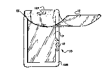
Referring now specifically to the drawings, an insert holder
according to the present invention is illustrated in Figures 1 and
2, and shown generally at reference numeral 10. Holder 10 is
formed of a plastic sheet 11, a plastic sheet 12 and an adhesive
frame 13. Sheets 11 and 12 and frame 13 all have the same
dimensions and are preferably provided with slots llA, 12A and 13A,
respectively, to receive a holding strap after assembly.
The adhesive frame 13 is assembled of a thin plastic or paper
substrate sheet having pressure sensitive adhesive layers applied
to opposite sides. The adhesive layers are protected by release
liners until adhesive frame 13 is used. Release liner 19 is scored
to provide individually removable segments l9A and l9B.
Insert holder 10 is assembled by first removing a release
liner from the back side of frame 13. This exposes an adhesive
layer 16 (see Figure 1), and the frame 13 is then adhered to
plastic sheet 11. Next, release liner segment l9A is removed to
expose a strip of the adhesive layer 17 across the top of frame 13.
Sheet 12 is placed in registration over frame 13 and the top
edge of sheet 12 is pressed against the exposed adhesive 17,
2~ 8
thereby securing sheet 12 and frame 13 together across the top
edges. This is shown in Figure 1.
At this stage, the remaining assembly may be deferred for as
long as desired, usually until the insert is ready to place between
the sheets 11 and 12. The frame 13 has a thickness which, when
applied to sheet 11, forms a template within which a photograph or
other card may be placed. 8y insuring that the insert is no larger
than, and preferably slightly smaller than, the open space inside
frame 13, the insert can be quickly and accurately placed between
the sheets 11 and 12, so that the insert is perfectly aligned with
the side edges of the sheets 11 and 12.
Then, the remaining frame segment l9B is peeled away from the
adhesive layer 17, and sheet 12 is pressed against adhesive layer
17 around the remaining periphery, sealing the insert permanently
inside the holder 10.
Holder 10 may be any suitable size. A preferred embodiment
provides a holder which is 2.38 inches wide and 3.5 inches long.
Frame segment l9A is .375 inches wide. Frame segment l9B is .25
inches wide. Slots llA, 12A, 13A are each .13 inches wide and .56
inches long.
Sheet 11 is .035 inch thick clear plastic. Sheet 12, which
serves as the display side of the holder 10 is .040 inch thick.
Frame 13 is preferably opaque to form the appearance of a frame or
border when applied as described above.
A further emhoAiment of the holder according to the invention
is shown in Figure 3 and broadly indicated at reference numeral 40.
Holder 40 i6 formed of a plastic sheet 41, a plastic sheet 42 and
an adhesive frame 43. Sheets 41 and 42 and frame 43 all have
substantially the same dimensions and are may be provided with
clots or holes (not shown) to receive a holding strap, chain or the
like after assembly in the manner described above.
Sheets 41 and 42 may be silk-screened or otherwise printed to
provide opaque, darkened or decorative border areas leaving
centrally-disposed transparent areas to display underlying
photographs, identification cards or the like.
The adhesive frame 43 is assembled of a thin plastic or paper
cubstrate sheet having pressure sensitive adhesive layers applied
to opposite sides. At least the adhesive layer on one side of the
frame 43 is protected by a release liner 46 (shown with a corner
folded down) until adhesive frame 43 i5 used. Then the release
liner 46 iS peeled off to eYros~ the adhesive.
The frame 43 has two die-cut openings 48, 49 to receive
photographs, identification cards or the like.
As is shown in Figure 3, two photographs or identification
cards can be placed back-to-back and then placed in the openings
48, 49. The thickness of the frame 43 is sufficient to hold the
inserts in their proper position until the sheets 41 and 42 are
adhered to opposite sides of frame 43.
Sheets 41 and 42 may be the same or different thicknesses,
for example .01" for front sheet 41 and . 02" for back sheet 42.
%~ 8
This provides proper rigidity to the assembled holder. Frame 43,
including the adhesive layers, is preferably .016" thick. The
dimensions of the sheets 41 and 42 and frame 43 are 3.375" by
2.125". Preferably the openings 48, 49 are very ~lightly larger
in dimension than the transparent areas of sheets 41, 42 to provide
a neat finished appearance.
The holder 40 may be assembled to a partial stage of
completion in an initial assembly process by a manufacturer and
shipped to a photographic studio or directly to the consumer for
final assembly after inserting photographs, identity cards or the
like into die-cut openings 48, 49. In the embodiment shown in
Figure 3, release liner 46 includes two release liner segments 46A
and 46B. After attaching the sheet 42 to frame 43 the release
liner segment 46A is removed and the top edge only of the sheet 41
is secured to the adhesive exposed on the top of the frame 43. The
sheet 41 is sufficiently flexible to allow the sheet 41 to be
flexed upwardly away from the surface of frame 43 to a degree
adequate to permit the photographs or identification cards to be
slipped into the openings 48, 49. This partial stage of assembly
is shown in Figure 4.
Final assembly is then accomplished by removing the release
liner 46B and pressing the sheet 41 against the newly-exposed
adhesive on the face of frame 43.
As is shown in Figure 5, an insert holder 40' is
illustrated, with prime reference numerals designating elements
structurally analogous to the insert holder 40 shown in Figures 3
38
and 4. A magnetic data strip 50 is placed on the cheet 41 or 42
in a suitable location. In Figure 5 the data strip 50 is shown on
sheet 42', and i8 positioned longitl~inAlly along sheet 42' near
one edge. Of course the data strip 50 can also be placed in other
positions on either sheet 41' or 42' APp~n~ i ng on the size and
shape of the other material which must be visible on the holder
40'. The provision of the magnetic data strip 50 enables a holder
to contain both highly personalized information ~uch as photographs
and fingerprints, as well as a substantial amount of information
in digital form on the data strip S0. Thus the issuer of the
holder with the magnetic strip 50 can much more easily control use
of the card by use of both visual comparison of the individual in
possession of the card with the photograph on the card, and
identification of the card by magnetic means through magnetic data
readers.
An insert holder and method of construction of an insert
holder according to several embodiments of the invention is
described above. Various details of the invention may be changed
without departing from its scope. Furthermore, the foregoing
description of the preferred embodiment of the invention and the
best mode for practicing the invention are provided for the purpose
of illustration only and not for the purpose of limitation--the
invention being defined by the claims.