Sélection de la langue

Search

Sommaire du brevet 2085689 

Énoncé de désistement de responsabilité concernant l'information provenant de tiers

Une partie des informations de ce site Web a été fournie par des sources externes. Le gouvernement du Canada n'assume aucune responsabilité concernant la précision, l'actualité ou la fiabilité des informations fournies par les sources externes. Les utilisateurs qui désirent employer cette information devraient consulter directement la source des informations. Le contenu fourni par les sources externes n'est pas assujetti aux exigences sur les langues officielles, la protection des renseignements personnels et l'accessibilité.

Disponibilité de l'Abrégé et des Revendications

L'apparition de différences dans le texte et l'image des Revendications et de l'Abrégé dépend du moment auquel le document est publié. Les textes des Revendications et de l'Abrégé sont affichés :

  • lorsque la demande peut être examinée par le public;
  • lorsque le brevet est émis (délivrance).
(12) Demande de brevet: (11) CA 2085689
(54) Titre français: ROULEAU POUR PRESSE A COURROIES SANS FIN
(54) Titre anglais: ROLLER FOR CONTINUOUS BELT PRESS
Statut: Réputée abandonnée et au-delà du délai pour le rétablissement - en attente de la réponse à l’avis de communication rejetée
Données bibliographiques
(51) Classification internationale des brevets (CIB):
  • B30B 03/00 (2006.01)
  • B27N 03/24 (2006.01)
  • B30B 05/06 (2006.01)
(72) Inventeurs :
  • GERHARDT, KLAUS (Allemagne)
(73) Titulaires :
  • G. SIEMPELKAMP GMBH & CO.
(71) Demandeurs :
  • G. SIEMPELKAMP GMBH & CO. (Allemagne)
(74) Agent: BORDEN LADNER GERVAIS LLP
(74) Co-agent:
(45) Délivré:
(22) Date de dépôt: 1992-12-17
(41) Mise à la disponibilité du public: 1993-06-19
Licence disponible: S.O.
Cédé au domaine public: S.O.
(25) Langue des documents déposés: Anglais

Traité de coopération en matière de brevets (PCT): Non

(30) Données de priorité de la demande:
Numéro de la demande Pays / territoire Date
P 41 41 833.6 (Allemagne) 1991-12-18

Abrégés

Abrégé anglais


18771
Abstract of the Disclosure
A belt press has a frame having horizontally extending
and vertically spaced upper and lower plates defining a horizon-
tally extending gap, respective upper and lower sets of drums
rotatable on the frame, respective upper and lower endless belts
spanned over the respective upper and lower sets of drums and
each having a working stretch lying between the plates, and re-
spective upper and lower sets of tubular rollers engaged between
the working stretches and the respective plates. Respective
upper and lower sets of rods traverse the respective rollers and
are connected together as upper and lower endless chains. A
drive connected to the drums advances the belts to move the work-
ing stretches horizontally in a transport direction to displace a
workpiece in the direction through the gap and the plates are
urged together with a pressure of between 300N/cm2 and 600N/cm2.
Each tubular roller has a wall thickness greater than 2mm, is
formed of a material such that it is not substantially deformed
when compressed diametrally between the respective plate and the
respective working stretch, has a mass which is smaller by a
factor of between 0.30 and 0.50 than a solid rod of identical
material and outside dimensions, and has a geometrical moment of
inertia that is smaller by a factor of between 0.50 and 0.65 than
a solid rod of identical material and outside dimensions.
- 11 -

Revendications

Note : Les revendications sont présentées dans la langue officielle dans laquelle elles ont été soumises.


18771
THE EMBODIMENTS OF THE INVENTION IN WHICH AN EXCLUSIVE
PROPERTY OR PRIVILEGE IS CLAIMED ARE DEFINED AS FOLLOWS:
1. In a belt press having
a frame having horizontally extending and vertically
spaced upper and lower plates defining a horizontally extending
gap;
respective upper and lower sets of drums rotatable on
the frame;
respective upper and lower endless belts spanned over
the respective upper and lower sets of drums and each having a
working stretch lying between the plates;
respective upper and lower sets of tubular rollers
engaged between the working stretches and the respective plates;
respective upper and lower sets of rods traversing the
respective rollers and connected together as upper and lower
endless chains;
drive means connected to the drums for advancing the
belts to move the working stretches horizontally in a transport
direction to displace a workpiece in the direction through the
gap; and
means for urging the plates together with a pressure of
between 300N/cm2 and 600N/cm2,
the improvement wherein each tubular roller
has a wall thickness of at least 2mm,
- 8 -

18771
is formed of a material such that it is not substan-
tially deformed when compressed diametrally between the respec-
tive plate and the respective working stretch;
has a mass which is smaller by a factor of between 0.30
and 0.50 than a solid rod of identical material and outside di-
mensions; and
has a geometrical moment of inertia that is smaller by
a factor of between 0.50 and 0.65 than a solid rod of identical
material and outside dimensions.
2. The belt press defined in claim 1 wherein the mass
of each tubular roller is smaller by a factor of about 0.40 than
a solid rod of identical material and outside dimensions.
3. The belt press defined in claim 1 wherein the geo-
metrical moment of inertia of each tubular roller is smaller by a
factor of about 0.60 than a solid rod of identical material and
outside dimensions.
4. The belt press defined in claim 1 wherein the roll-
ers are cylindrical and each have an outside diameter of about
18mm and an inside diameter of about 14mm.
- 9 -

18771
5. The belt press defined in claim 1 wherein the drive
means advances the belts at a speed of at least 250mm/sec.
6. The belt press defined in claim 1 wherein the work-
ing stretches have a length of at least 50m.
- 10 -

Description

Note : Les descriptions sont présentées dans la langue officielle dans laquelle elles ont été soumises.

~85~
18771
ROLLER FOR CONTINUOUS BELT PRESS
SPECIFICATION
Field of the_Invention
The present invention relatas to a belt press. More
paxtlcularly this invention concerns such a press whose belts are
~uppoxted on arrays of rollers and for the rollers used in the
press.
Background of the Invention
A standard belt press as described in US patents
4,417,866, 4,480,978, and 4,613,293 has a frame having horizon-
-tally extending and vertically spaced upper and lower plates
de*ining a horizontally extending gap having an upstream end and
a downstxea~ end, vertically spaced upper and lower upstream
d~u~s rotatable about respective horizontal axes at the upstream
and, vertically spaced upper and lower downstream drums rotatable
~bout respective horizontal axes at the downstream end, and upper
and lower endless belts spanned over the respective upper and
lower drums and each having a working stretch lying between the
plates and a return stretch. Upper and lower sets of rollers
engaged between ths working stretches and the respective plates
can be recirculated as the belts are advanced to move the working
-- 1 --

2~568~
18771
stretches horizontally in a transport direction to displace a
workpiece in the direction through the gap so that the workin~
stretches are supported on the respective plates by these roll-
ers. The entire press is also normally heated to activate a
binder in the workpiece.
Typically the rollers have a diameter of between 15mm
and 25mm, normally 20mm, and are subjected to a pressure between
300N/cm2 and 600N/cm2, normally 500N/cm2. As a result the stan-
dard prior-art practice has been to use solid rods as the roll-
ers. Such solid rods can be made to very tight tolerances ofdiameter, straightness, and the like. Nonetheless in a long
press, which can exceed 50m in length, this means that a huge
mass of such rollers must be moved.
It has been suggested in German patent 3,534,996 filed
01 October 1985 and in European patent 236,905 issued 03 April
1991 to R. deBrock (based on DE 3,608,487 filed 14 March 1986) to
make the rollers tubular. These rollers are of extremely thin
wall thickness, well under 2mm, so that they deform in the press
and act as spring elements. The service life of such rollers,
which deform substantially in use, is therefore relatively short.

20~5~
18771
Obiects of the Invention
It is therefore an ob~ect of the present invention to
provide an improved roller for a belt press.
Another object is the provision o~ such an improved
roller for a belt press which overcomes the above-given disadvan-
tages, that is which ensures highly efficient press operation
without in any way making the press less effective than a press
using solid rollers.
Summary__f the Invention
The instant invention is used in a belt press having a
frame having horizontally extending and vertically spaced upper
and lower plates defining a horizontally extending gap, respec-
tive upper and lower sets of drums rotatable on the frame, re-
spective upper and lower endless belts spanned over the respec-
tive upper and lower sets of drums and each having a working
stretch lying between the plates, and respective upper and lower
s~ts of tubular rollers engaged between the working stretches and
the respective plates. Respective upper and lower sets of rods
traverse the respective rollers and are connected together as
~O upper and lower endless chains. A drive connected to the drums
advances the belts to move the working stretches horizontally in
a transport direction to displace a workpiece in the direction
through the gap and the plates are urged together with a pressure
- 3 -

2 ~ 9
18771
of between 300N/cm2 and 600N/cm2. According to the invention
each tubular roller has a wall thickness greater than ~mm, is
formed of a material such that it is not substantially deformed
when compressed diametrally between the respective plate and the
S respective working stretch, has a mass which is smaller by a
factor of between 0.30 and 0.50 than a solid rod of identical
material and outside dimensions, and has a geometrical moment of
inert~ia that is smaller by a factor of between 0.50 and 0O65 than
a solid rod of identical material and outside dimensions.
More particularly according to the invention the mass
of each tubular roller is smaller by a factor of about 0.40 than
a solid rod of identical material and outside dimensions. In
addition the geometrical moment of inertia of each tubular roller
is smaller by a factor of about 0.60 than a solid rod of identi-
cal ~aterial and outside dimensions. The rollers are cylindrical
and each have an outside diameter of about 18mm and an inside
diameter of about 14mm. Furthermore the drive advances the belts
at a speed of at least 250mm/sec and the working stretches have a
l~n~th of at least 50m.
~0 The relatively thick-walled tubular rollers according
to this invention have proven themselves to be a huge improvement
on the thinner-walled tubular rollers of the prior art. There is
very little spring effect or compression of the inventive tubular
rollers in the press. These tubes fit with quite some play on
the respective chain rods and reduce the hertz tensions by a fac
-- 4 --

2 ~
18771
tor of about 0.994. Surprisingly this positively affects the
rolling friction by greatly reducing it.
With the system of this invention the overall mass of
the rollers is substantially reduced, thereby generally reducing
the mass that the various drives and roller-recirculating systems
must deal with and making it possible for the press to operate
more rapidly. Even in the return stretch, when the rollers are
being moved outside the press gap from the downstream end of the
press to its upstream end, the droop or bending deformation of
these tubes is reduced by about 63%, making inserting them into
the upstream working-stretch end aasier.
In addition it has surprisingly been found that heat
trahsfer from the heated press platens through the rollers to the
stainless-steel belts and thence to the workpiece is not delete-
riously affected by the fact that the rollers are tubular insteadof being solid. In fact the reduced heat capacity of these roll-
ers decreases by about half the amount of heat the system needs
to run. Evidently the relatively thick walls of the tubes allow
the heat transfer to be as good as for solid-core rollers, and
the fact that the rollers have no cores that must be heated means
that the system can be up to temperature faster than a prior-art
one.

2 ~
18771
Brief Description of the Drawin~
The above and other objects, features, and advantages
will become more readily apparent from the following, reference
being made to the accompanying drawing in which:
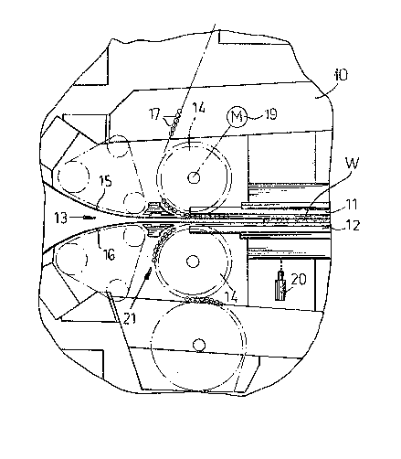
Fig. 1 is a vertical section through the upstream end
a belt press according to the invention; and
Fig~ 2 is a large-scale cross section through one of
the xollers of the press.
Specific DescriPtion
As seen in Fig. 1 a belt press has a rame 10 having
horizontally extending and vertically spaced upper and lower
platas 11 and 12 de~ining a horizontally extending gap 13.
Respective upper and lower sats of drums 14 rotatable on the
~ra~e 10 carry respective upper and lower endless belts 15 and 16
1~ sp~nned over the respective upper and lower sets of drums 14 and
~ach having a working stretch lying between the plates 11 and 12.
Respective upper and lower sets of tubular rollers 17
~n~agad between the working stretches and the respective plates
11 and 12 are carried on respective upper and lower sets of rods
~0 18 (See Fig. 2.) traversing the respective rollers 17 and con-
nected together as upper and lower endless chains. A drive motor
19 connected to the drums 14 advances the belts 11 and 12 to move
the working stretches horizontally in a transport direction to
-- 6 --

18771 ~$~6~
displace a workpiece W through the gap 13. The plates are urged
together by an actuator ~0 with a pressure of between 300N/cm2
and 600N/cm2.
As best seen in Fig. 2 each tubular roller 17 has a
wall thickness T of slightly more than 2mm and an outside diame
ter of about 18mm. In addition each tube 17 is formed of a mate-
rial such as steel so that it is not substantially deformed when
compr~Qss~d diametrally between the respective plate and the re-
spective working stretch and has a mass which is smaller by a
factor of between 0.30 and 0.50 than a solid rod of identical
material and outside dimensions. Furthermore each tube 17 has a
geometrical moment of inertia that is smaller by a factor of
between 0.50 and 0.65 than a solid rod of identical material and
outside dimensions.
-- 7 --

Dessin représentatif
Une figure unique qui représente un dessin illustrant l'invention.
États administratifs

2024-08-01 : Dans le cadre de la transition vers les Brevets de nouvelle génération (BNG), la base de données sur les brevets canadiens (BDBC) contient désormais un Historique d'événement plus détaillé, qui reproduit le Journal des événements de notre nouvelle solution interne.

Veuillez noter que les événements débutant par « Inactive : » se réfèrent à des événements qui ne sont plus utilisés dans notre nouvelle solution interne.

Pour une meilleure compréhension de l'état de la demande ou brevet qui figure sur cette page, la rubrique Mise en garde , et les descriptions de Brevet , Historique d'événement , Taxes périodiques et Historique des paiements devraient être consultées.

Historique d'événement

Description Date
Inactive : CIB de MCD 2006-03-11
Le délai pour l'annulation est expiré 1995-06-18
Demande non rétablie avant l'échéance 1995-06-18
Réputée abandonnée - omission de répondre à un avis sur les taxes pour le maintien en état 1994-12-19
Inactive : Demande ad hoc documentée 1994-12-19
Demande publiée (accessible au public) 1993-06-19

Historique d'abandonnement

Date d'abandonnement Raison Date de rétablissement
1994-12-19
Titulaires au dossier

Les titulaires actuels et antérieures au dossier sont affichés en ordre alphabétique.

Titulaires actuels au dossier
G. SIEMPELKAMP GMBH & CO.
Titulaires antérieures au dossier
KLAUS GERHARDT
Les propriétaires antérieurs qui ne figurent pas dans la liste des « Propriétaires au dossier » apparaîtront dans d'autres documents au dossier.
Documents

Pour visionner les fichiers sélectionnés, entrer le code reCAPTCHA :


Pour visualiser une image, cliquer sur un lien dans la colonne description du document (Temporairement non-disponible). Pour télécharger l'image (les images), cliquer l'une ou plusieurs cases à cocher dans la première colonne et ensuite cliquer sur le bouton "Télécharger sélection en format PDF (archive Zip)" ou le bouton "Télécharger sélection (en un fichier PDF fusionné)".

Liste des documents de brevet publiés et non publiés sur la BDBC .

Si vous avez des difficultés à accéder au contenu, veuillez communiquer avec le Centre de services à la clientèle au 1-866-997-1936, ou envoyer un courriel au Centre de service à la clientèle de l'OPIC.

({010=Tous les documents, 020=Au moment du dépôt, 030=Au moment de la mise à la disponibilité du public, 040=À la délivrance, 050=Examen, 060=Correspondance reçue, 070=Divers, 080=Correspondance envoyée, 090=Paiement})


Description du
Document 
Date
(aaaa-mm-jj) 
Nombre de pages   Taille de l'image (Ko) 
Revendications 1993-06-18 3 60
Abrégé 1993-06-18 1 37
Dessins 1993-06-18 1 28
Description 1993-06-18 7 213
Dessin représentatif 1998-09-09 1 22