Sélection de la langue

Search

Sommaire du brevet 2085709 

Énoncé de désistement de responsabilité concernant l'information provenant de tiers

Une partie des informations de ce site Web a été fournie par des sources externes. Le gouvernement du Canada n'assume aucune responsabilité concernant la précision, l'actualité ou la fiabilité des informations fournies par les sources externes. Les utilisateurs qui désirent employer cette information devraient consulter directement la source des informations. Le contenu fourni par les sources externes n'est pas assujetti aux exigences sur les langues officielles, la protection des renseignements personnels et l'accessibilité.

Disponibilité de l'Abrégé et des Revendications

L'apparition de différences dans le texte et l'image des Revendications et de l'Abrégé dépend du moment auquel le document est publié. Les textes des Revendications et de l'Abrégé sont affichés :

  • lorsque la demande peut être examinée par le public;
  • lorsque le brevet est émis (délivrance).
(12) Demande de brevet: (11) CA 2085709
(54) Titre français: GUIDE DE PIECE A USINER
(54) Titre anglais: WORKPIECE GUIDE
Statut: Réputée abandonnée et au-delà du délai pour le rétablissement - en attente de la réponse à l’avis de communication rejetée
Données bibliographiques
(51) Classification internationale des brevets (CIB):
  • B27C 1/12 (2006.01)
  • B23Q 3/00 (2006.01)
  • B27B 25/02 (2006.01)
(72) Inventeurs :
  • VAN GELDER, HARRY (Etats-Unis d'Amérique)
  • VAN GELDER, HARRY (Etats-Unis d'Amérique)
(73) Titulaires :
  • HARRY VAN GELDER
  • HARRY VAN GELDER
(71) Demandeurs :
(74) Agent: MACRAE & CO.
(74) Co-agent:
(45) Délivré:
(22) Date de dépôt: 1992-12-17
(41) Mise à la disponibilité du public: 1993-08-04
Licence disponible: S.O.
Cédé au domaine public: S.O.
(25) Langue des documents déposés: Anglais

Traité de coopération en matière de brevets (PCT): Non

(30) Données de priorité de la demande:
Numéro de la demande Pays / territoire Date
829,226 (Etats-Unis d'Amérique) 1992-02-03

Abrégés

Abrégé anglais


ABSTRACT
A workpiece guide to help feed boards into a woodworking machine
such as a power saw. The guide is adapted to hold the board against the guide
fence as the board is ted into the saw by pressing a knurled wheel down against the
board. The wheel is slightly angled to move the board toward the fence and is
pressed down against the board by a leaf spring thus keeping the board from riding
up on the blade.

Revendications

Note : Les revendications sont présentées dans la langue officielle dans laquelle elles ont été soumises.


THE EMBODIMENTS OF THE INVENTION IN WHICH AN EXCLUSIVE
PROPERTY OR PRIVILEGE IS CLAIMED ARE DEFINED AS FOLLOWS:
1. For use with a power woodworking tool having a table, a guide fence
adjustably fixed to said table and cutter means extending above said table adjacent
said guide fence, feed assisting guide means comprising a yoke mounted astraddleof said fence, and movable vertically relative thereto, wheel means pivotally fixed
on one leg of said yoke and on the same side of said fence as said cutter means,said wheel having an axis of rotation tilted from a perpendicular to said fence, and
means to bias said wheel towards said table whereby a workpiece on said table will
be held against said fence.
2. The feed assisting guide means of claim 1 in which said means to bias
said wheel means comprises a spring means attached to said yoke and said fence.
3. The feed assisting guide means of claim 1 in which said spring means
includes a leaf spring having one end attached to said yoke and a second end fixed
to said fence.
4. The feed assisting guide means of claim 1 in which said yoke has two
legs, said wheel means being rotatably mounted on one leg, adjustable slide means
mounted on the second of said legs, said slide means being adapted to engage said
fence to allow vertical movement of said yoke and to prevent movement of said
yoke laterally of said fence.
5. The feed assisting guide means of claim 4 in which said slide means
is adjusted by a screw threaded through said second of the legs.

Description

Note : Les descriptions sont présentées dans la langue officielle dans laquelle elles ont été soumises.

7 ~ ~
WORK}'II-: CE GUIDE
BACKGROUND AND SUMMARY OF T~IE INVI-~Nl~ION
This invention pertains to safety means lor woo(lworking power tools,
and more particularly to a device to hold a workpiece agaillst the guide fence of
5 SlJCh a tool as the workpiece is moved past a rotating clltter.
Woodworking power tools are notably dallgerol~s, prhlcipally because
cutting tools for wood cut at relatively high speeds ancl are thus apt to cut
operator's misplaced hands quickly. Power saws, shapers, routers and the like are
particularly difficult to guard because the operator typically uses a hand to feed the
10 workpiece past the cutter. The object of almosl any safety device for sllch tools
mllst be to keep the operator's hands at a safe clistance trom the clltter.
In order to rip-cut wood properly on a power saw the piece being cut
m~lst be held firmly against the guide fence as the piece passes the saw. The piece
mllst also be fed through the saw. My co-pending application, ~erial No. 718,57~,
filed June 20, 1991 proposes a safe feeding mechanism. The purpose of the
present device is to hold the workpiece against the fence. Although it is described
in conjunction with a power saw, it will be obvious that a similar problem exists in
a shaper or router where a workpiece is also longitudinally moved past a rotating
cutter although the axis of rotation may be vertical rather than hori~ontal. In such
20 a machine, the same danger is present, and a device embodying the present
inventiolt may also be useful.
ycc/bh

2~7~
BRIEF DESCRIPTlON OF T~IE DRAWINC~S
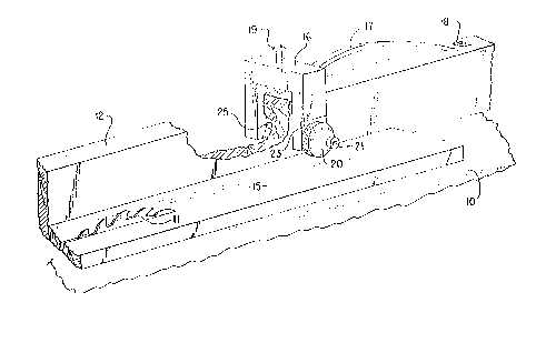
FIG. I is a perspective view of a woodworkillg table saw with the
feeder device in place on the guide fence,
Fl~. 2 is an en(l view of the f`ence showillg the fee(ler in place, and
S FIG. 3 is a view from line 1-~ of FIG. 2.
DESC~IPTION
Briefly my invention comprises a sate-feeding device fs)r a power
driven woodworking machine using an angled, knurled wheel to hold a wood
workpiece against a guide fence on such machine.
More particularly, and referring to the drawings, the device isdesigned
~; for use on any of several different types of woodworking tools. However, is will be
described in connection with an ordinary table saw because that partic-llar tool is
a very familiar type of application.
A table saw includes a table 10 on which is moullte(l a motor (not
shown) driving a rotating saw blade 11. A guide fence 12 wou]d normally be
movably fixed to the table so that the space between it and the saw blade could be
varied to cut a variety of board widths. In use, the board or workpiece 15 is
slidably fed past the blade 11 and over the surface of the table 10 while being held
laterally against the fence 12.
The present invention is directed toward the latter function. To tllat
end, a yoke-shaped carrier 16 is provided astraddle the fence 12. This yoke 16 is
held in a longitudinal position relative to the fence by an arched leaf spring 17
ycc/bh 2

7 ~ 9
having one end fixed to the cross member of the yoke and the other en(l lixe(l to
the fence by a screw 18 or the lil~e. The spring 17 is long enollgh to allow
considerable vertical movement of the yoke 16 an(l may be arched to provide
relatively constant pressllre so that various thickness of workpieces 15 may be
S accommodatecl. An ~adjustlllellt screw 19 nlay be use(l to a(ljllsl different
thicknesses of workpiece while preserving downwald pressllre on the workpiece 15.
On one leg of the yoke 16, a knurled wheel 20 is rotatably mounted
on an axle 21 which may be in the form of a screw threadecl into the material of
the yoke. This wheel is free to rotate on the axle. However, as best shown in
10 FIG. 3, the axis about which the wheel rotates is not perpendicular to the surface
of the fence 12, but is at a slight angle from the perpendiclllar. The plane of
rotation of the wheel is thus angled slightly so as to pull the workpiece 15 towards
the fence 12. The yoke 16 may be slightly notched as at 23 to accommodate the
angled alignment.
On the leg of the yoke 16 opposite the wheel 20,1 provide adjustment
and holding means to provide for use of the device on fences which may be of
different thickness. The illustrated device is simply a nylon screw 25 threaded
through the yoke so that it can slide on the outer side of the guide fence 12. The
screw 25 should not press tightly against the fence, but rather sho~dd allow vertical
20 sliding of the yoke 16 so that the leaf spring 17 will perform its function of holding
the wheel 20 firmly against the workpiece 15. A nylon screw is h~(licated so that
yoke will slide withollt bindillg or scratching the fence.
ycc/bh 3

2~7~
Althougll the slicle 25 is showll as a simple screw, it will be obviolls
that some sort of adde(l slicle device at the encl of the screw aci jacellt the f'ence may
be desirable ~o preserve the sliding ability. This may be some simple broader cup
device on the end of the screw 2~ adapte(l to slide against the l`ence, or may be
S a more elaborate device-particularly l`ol use with a metal fellce where the outer
surface is not flat. Sucll variations should be well within the ability of one skilled
in the art.
In use, the device must first be fixed to the top of the fence 12 by the
screw 18 through the spring 17. The yoke must be astraddle of the fence 12 with
the wheel 20 on the same side of the fence as the saw blade 11. The axle 21 of the
wheel 20 will then be angled so that a board 15 will tend to be pulled toward the
fence as it is pusheci (usually), or pulled by a device such as that' d'escribed in my
previously noted copending application, past the blade 11. The acljustable sliding
device illustrated as the screw 25 should be adjusted to provicle for easy vertical
15 movement of the yoke, but for little or no lateral movement. The screw 19 is also
adjusted for the thickness of the workpiece 15.
As the board or workpiece 15 is now moved first under the wheel 20,
that wheel will be pushed upward against the bias of the spring 17. As the
workpiece moves toward and past the blade 11, it will be urged toward the ~ence
20 12 by the angled wheel with its knurled outer surface. Thus, Ihe workpiece will
tend to be held against the fence as the workpiece is cut, as desireci.
ycc/bh 4

Dessin représentatif
Une figure unique qui représente un dessin illustrant l'invention.
États administratifs

2024-08-01 : Dans le cadre de la transition vers les Brevets de nouvelle génération (BNG), la base de données sur les brevets canadiens (BDBC) contient désormais un Historique d'événement plus détaillé, qui reproduit le Journal des événements de notre nouvelle solution interne.

Veuillez noter que les événements débutant par « Inactive : » se réfèrent à des événements qui ne sont plus utilisés dans notre nouvelle solution interne.

Pour une meilleure compréhension de l'état de la demande ou brevet qui figure sur cette page, la rubrique Mise en garde , et les descriptions de Brevet , Historique d'événement , Taxes périodiques et Historique des paiements devraient être consultées.

Historique d'événement

Description Date
Inactive : CIB de MCD 2006-03-11
Le délai pour l'annulation est expiré 1995-06-18
Demande non rétablie avant l'échéance 1995-06-18
Réputée abandonnée - omission de répondre à un avis sur les taxes pour le maintien en état 1994-12-19
Inactive : Demande ad hoc documentée 1994-12-19
Demande publiée (accessible au public) 1993-08-04

Historique d'abandonnement

Date d'abandonnement Raison Date de rétablissement
1994-12-19
Titulaires au dossier

Les titulaires actuels et antérieures au dossier sont affichés en ordre alphabétique.

Titulaires actuels au dossier
HARRY VAN GELDER
HARRY VAN GELDER
Titulaires antérieures au dossier
S.O.
Les propriétaires antérieurs qui ne figurent pas dans la liste des « Propriétaires au dossier » apparaîtront dans d'autres documents au dossier.
Documents

Pour visionner les fichiers sélectionnés, entrer le code reCAPTCHA :


Pour visualiser une image, cliquer sur un lien dans la colonne description du document. Pour télécharger l'image (les images), cliquer l'une ou plusieurs cases à cocher dans la première colonne et ensuite cliquer sur le bouton "Télécharger sélection en format PDF (archive Zip)" ou le bouton "Télécharger sélection (en un fichier PDF fusionné)".

Liste des documents de brevet publiés et non publiés sur la BDBC .

Si vous avez des difficultés à accéder au contenu, veuillez communiquer avec le Centre de services à la clientèle au 1-866-997-1936, ou envoyer un courriel au Centre de service à la clientèle de l'OPIC.


Description du
Document 
Date
(aaaa-mm-jj) 
Nombre de pages   Taille de l'image (Ko) 
Page couverture 1993-08-04 1 15
Abrégé 1993-08-04 1 11
Revendications 1993-08-04 1 32
Dessins 1993-08-04 1 27
Description 1993-08-04 4 121
Dessin représentatif 1998-09-10 1 17