Note : Les descriptions sont présentées dans la langue officielle dans laquelle elles ont été soumises.
?,j5~ s r~ ;7J~
MODULAR PNEUMATIC CONTROL SYSTEMS
This invention relates to modular pneumatic
controls, and particularly, modular units which are all
of the same configuration so that they can be
interconnected using the same fittings thus obviating
specialized modular units and fittings as presently
employed in the prior art.
The manifolding oE pneumatic control devices is well
known. For example, U. S. patents 4,0939329; 4,095,863
and 4,095,864 illustrate the need for a separate manifold
device on which the control de~ices are pla~ed. In
particular, the '329 and the '864 patents show that
di:fferent types of co~trol devices or manifold units are
employed in a control ~ystem. U. 5. patent 4,245,5~9
describes a control device with a ~diaphragm stack wherein
the internal functions are similar to that employed in
the modular unit of this~:invention. ~owever, it is not
capable of interconnection in the manner hereinafter
: ~ descrlbed. In U. S. patent 4,027,692 lo~ic modules are
shown which are presented in a cascade form and are
~ : em,ployed for controllin~ machines by pneumatic means.
: ~ a'ch one of the modular units has different input~
: a~so~iated with it as well as~requiring a diffcrent unit
: : referred to as a connecting unit. ~ :
While the prior~ art control units af~ord a means of
manifolding several control units into a system, they do
not afford a simplified modular control unit:wherein each
:
: : '
:~:
~ .
.
. ~ .
unit is of the same configuration and can be
interconnected to a common Eluid input source.
It is an advantage of the present invention to
provide aa improved pneumatic control device wherein all
of the devices are of the same geometric configuration.
It is another advantage of this invention to provide
a pneumatic control device wherein all of the connections
to the devices are o~ the same type, the same size and
are located at the same locations.
It is yet another advantage of the invention to
provide a modular control unit of the foregoing type
wherein the modular units are plugged together using
couplings with the main air piped to only one device and
internal air passages delivering the air to all of the
other modular units.
It is still another advantage of the invention to
provide a modular unit of the foregoing type wherein any
series or parallel combination of signalling air can be
employed.
Other advantages are a modular control unit wherein
the housing can accommodate a multiplicity of control
functions yet can be produced with a minimum cost and
assembly procedures.
The fore~oing advantages are accomplished and the
shortcomingg of the prior art are overcome by the presen~
pneumatic control device wherein a module is provided by
a body member having two substantially identi~al wall
members which are arran~ed opposite each other. There is
a cavity in each body member with a fluid regulator means
in the cavityO A fluid passage extends from a first wall
to an opposing second wall~ A first fluid input passage
extends between the second wall and a third wall, and a
fluid output passage extends between the first wall and
the third wall, with all of the fluid passages
communicating with the cavityc In one aspect, all of the
.
~ ~.
_3_
fluid passages are constructed and arranged to selec-
tively receive identical fluid connection means or plug
means.
In one preferred embodiment, there i3 at least one
additional ~1uid module identical to a first module.
Pluid connection means interconnect the fluid passages
between the first and second walls of said modules,
There are plug means for insertion into said first fluid
pas~age and the first fluid input passage at a second
wall of one of the additio~al fluid modules and for
insertion into the fluid output passage at the first wall
of said first module. There are additional plug and
fluid connection means for selective insertion into the
first fluid input and the output passages at the first,
second and third walls of the modules.
In other preferred embodiments, the fluid passages
are pneumatic fluid passages; the fluid re~ulator means
is provided by a diaphragm disposed in the cavity for ::
contact with a valve member, and the cavity receives one
: 20 or more diaphragms without modification of the body
member.
Ir. still another preferred embodiment, the modules
are formed from cubic body members with a fluid passage
extending through the body member in a linear manner, and
the fluid input and ou~put passag~s also communicate with
the exterior of the body member through an additional
: connecting wall surface.
Fig. 1 is a diagrammatic view illustrating a typical
prior art pneumatic con~rol system.
Fig. 2 is a diagrammatic view illustrating the fluid
control apparatus of the present invention.
Fig. 3 is a perspective view showing two of ~he
modules of the present invention for lnterconnection.
~ig. 4 is a sectional view taken along line 4-4 of
.35 Fig. 3 but with the two modules in an ass~mbled
condition.
. ' : : . ,
, ' ' '
., ~ , '
:: '
.
' :~/f ~ q~ l S .'~ ~1 .~ i ' :!,~. i _ 7~'l A t ~ ,~
Fig. 5 is a view in~.vertical section taken along
line 5-5 of Fig. 4.
Fig. 6 is a view in vertical section illustrating
one of the modules of the present invention taken along
line 6-6 of Fig. 3.
Fig. 7 is an assembly view o~ the module shown in
Fig. 6.
Fig. 8 is a view similar to Fig. 6 illustrating an
additional embodiment of the module.
Fig. 9 is a view in horizontal section of the module
shown in Fig. 6 taken along line 9-9 of Fig. 6.
~ ig. 10 is a top plan view of the module shown in
Fig. 6 with a portion shown in cross section.
Referring to Fig. 1, a typical prior art pneumatic
control apparatus i~ shown generally at 10. It includes
three modular pneumatic control devices 11, 12 and 13
which in normal practice has different geometric
configurations. The usual main air is supplied
independently to the openings 14, ].4' and 14", through
the main air line 17. Each of the units will have fluid
input passages 15, 15' and 15" as well as output passages
16, 16' and 16". It is recognized that within each of
the modules there is some type of ~egulator means which
is responsive to the input signal such as through line 18
to activate the regulator means in the unit so that at a
predetermined pressure level an output of air will exit
from the output 16 and is transferred to the conduit
22. Conduit 22 in turn is interconnected to the input
opening 15' of unit 12. A further signal is generated
from device 12 through the output opening 16' and through
the line 20. The device 13 is not interconnected to the
devices 11 or 12. Input and output signals are conveyed
by the input line 13 and output line 21 when connected to
the respective input opening 15" and the output opening
16". It will be recognized that in the prior art con-
struction there is utilized different configurations of
the control devices which require a multiplicity of
, ~. ' , ' ' ' '
. . , . , . - . , .
,': .' ', - ~ , :,'
., ' , - - ~, . . .
different interconnecting fittings such as the main air
line 17, the inlet lines 18 and 19 as well as the
interconnectiny line 22 and the outlet lines 20 and 21.
In contrast to the system shown in Fig. 1~ is the
modular fluid control apparatus of this invention which
is shown generally at 30 in ~ig. 2. The fluid control
apparatus 30 includes three identical devices 31, 32 and
33 which are of a cubic construction. As each of the
units has essentially the same passages therethrough,
only the ones shown in conjunction with the device 31 are
described at this stage in detail with the others having
the same numbers only they are "primed" or "double -
primed"~ Referring specifically to modular device 31, it
has a main air conduit 34 which extends linearly from the
first side 31r to a second side 311. The conduit 34
terminates in openings 34a and 34b for receiving, for
example, a plu~ 41 and a coupling 40, respectively. An
L-shaped inlet passage 35 also communicates with the
second side 311 through the orifice 35a and to a third
side 31t by the orifice 35b. An ~-shaped outlet passage
36 cr Inicates with the first side 31r through the
orifice 36a and to the third side 31t by the orifice
36b. As is seen in Fig. 2, the main air conduits 34, 34'
and 34" are interconnected by the couplings 40 and with a
main air supply indicated at 29~ The ve~atility of the
devices is shown in Fig. 2 where, for example, a variety
of input and output co~duits 37 and 38, respectively, are
connec~ed to their respective inlet and outlet passages
of the devices. Those passages which are not utilized~0 are provided with plugs 41. In this manner and, for
le, in conjunction with device 33, an input signal
is provide~ ~y the inlet line 37 and an outlet signal is
provided by the outlet conduit 38. This provides a
parallel connection.- However, in conjunction with
devices 31 and 32, these are interconnected in a series
manner with the inlet conduit 37 connected to the inlet
passage 35, wherea~ the outlet conduit 38 is connected to
' . : :
~ 7 ~ J 7 .L~ ~ r: J~7<~ 7Y ~
the outlet passage 36' and the outlet passage 36 and
inlet passage 35' being closed by the plugs 41. As later
described in more detail, device 33 inlet passage 35" and
outlet passage 36" communicate with an internal regulator
means as does main air conduit 34".
Referring specifically to Figs~ 3, 4 and 5, there it
is illustrated the ease of interconnecting modular
devices 31 and 33 for example. Each of the units has two
projecting connectors 43 and 43a which extend frcm
opposing lower and upper back sides. Each of the
connectors 43 and 43a has a "T"-shaped recess 48 to
receive, for example, a screw for mounting the devices to
a mounting plate or board. ~hen mounted, the connectors
and screws will be covered by insertion into an opening
such as 44" in the device 33. It will be understood that
not both of the connectors need be utilized for
attachment as these units are made in a symmetrical
manner. To make certain that the units are assembled in
the proper manner, it will be noted that there are
20 locating pegs such as 46, 46" and 46a" ~See Fig. 6).
These will fit into corresponding openings such as 39 and
39' in an opposing unit. In order to assure proper
orientation and as will best be seen in conjunction with
Fig. 6, peg 46" is square whereas peg 46a" is round for
fi~ting into round and square open.ings at the top and
bottom, respectively.
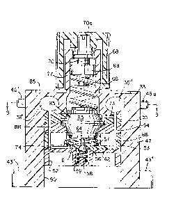
~ eferring specifically to Figs. 6 and 7, a typical
fluid regulator means is shown inside the device 33 and
133. As seen in Fig. 6, device 33 has a cavity 50 which
houses a bottom plate 52 as well as a retainer plate 53,
and diaphragm plates 54 and 55 for housing diaphragms 92,
93 and 94 as well as stack plates 64 and 65. These form
a diaphragm stack generally 95 which will move in the
cavity 50 in response to various pressures or vacuum
conditions, as is well known in the art (see, for
example, U. S. patent 4,245,549). A combination supply
and exhaust mushroom shaped valve 56 is biased by the :~
:,
.
, ,, ...... , ~ ~ .
.. - : . . . . ... . .
~ ,, - ~ - : ~ ~ .. :: . , . :
, - , .
: '" ' .', '-,, ' ' ' ~ '' ''
. ... ~ . : -. .. .
r ~ ??~
spring 59 positioned on the pcst 58 for seating against
supply valve seat 57. As best seen in ~ig. 7, the val~e
has a small diameter portion 56a for sealing against a
second valve seat 81a in a spring retainer 81 which
serves as an exhaust valve. A spring 61 is positioned
between the retainer 81 and the plate 62 to urge the
diaphragm stack 95 upwardly. The stack 95 including the
stack plates 64 and 65 are secured to the diaphragms 92,
93 and 94 by the screw 78 and washer 79 which fit into
the threaded portion 81b of the retainer 81. There is
also a spri~g 66 for urging the diaphragm stack 95
downwardly. It i5 engaged by the threaded adjustment nut
69 at one end and with the retainer 80 at the opposing
end. A threaded stem 70 engages the adjustment nut 69
for this purpose and is rotatably captured in the neck
77. As best seen in Fig. 6, a portion of the spring 66
is accommodated in the neck 77 of the device 33 as is the
adjustment nut 69 and the threaded stem 70. The turning
of the threaded stem 70 by means o:E the slotted head 70a
adjusts the tension on the spring 66, and accordingly the
tension on the diaphra~m stack 95. Referring back to
Fig. 7, it is seen that the dial kllob 68 is secured to
the stem 70 by the screw 51. Rotation of the dial knob
68 is limited by the stop 67 riding in the groove 68a
which will have a stop surface (not shown). An indicator
dial ring 85 is positioned adjacent the knob 68.
Fig, 75 9 and 10 illustrates ~he interconnection of
the plate members 52-55 inside the device 33. This is
effected by eight screws 82 which extend through the
plates as w~11 as through the screw holes 33s in the body
47. For this purpose, there are accommodating nut well
91 in the upper surface of the body 33b to accommodate
the nuts 83 attached to the screws 82. A gasket 84 is
positioned between plates 53 and 52.
Fi~s. 6 and 9 further illustrate communication in
the device 33 by the input and output signals as well as
the main air supply. Inlet passage 35" allows
~ .
~ , , , . _
pressurized signal air to enter through passages 86 and
73 to effect a.downward movement of the diaphragm stack
95. This effects an opening of the valve 56 which in
turn allows air from the main air supply in main air
eonduit 34" to flow through passage 89 to supply valve
seat 57 and flow outwardly through passages 74 and 88 to
outlet passage 36" in a manner well known for this
device. Referring specifically to Fig~ 9, it is seen
that there are additional inlet passages 39 and 42 in the
body 47 conneoting with passages 87 and 90, respec-
tively. These extend downwardly into the body 47 for
introducing secondary and tertiary inputs to the
diaphragm stack 95. Central cavity portion 33C
accommodates the spring 66 and the associated retainer 80
as previously explained.
An alternative embodiment is shown generally at 133
in Fig. 8. Similar components are designated with the
same numbers as referred to in ~onjunction with unit 33
except they are indicated in the "100 series". A
difference between unit 33 and 133 is the fact that there
are additional diaphragms 196 and 197 as well as plates
160, 163 and stack plates 167 and 175. This provides
additional co~trol chambers as represented by the
numerals 198-202. As stated earlier, the use of the
movable diaphragm stack 195 to e~fect a control function
in the modular device 133 is well known in the art.
~asically, a siqnal in the form of pressurized signal air
such as would be introduced from inlet passage 135" and
passages lB6 and 173. From passa~e 173 it enters a
control chamber such as 199. This signal air in
conjunction with other sig~al air introduced into other
chambers such as 198 can oause a pressure differential
acting across the diaphram 193. This can cause diaphragm
stack 195 to move downwardly and valve 156 to be moved
of~ seat 157 to thereby allow supply air from the main
air conduit 34" to be released as an output through
passage~ 174, 188 and outlet pas~age 136". An exhaust
~ :
. : . ' : :
:
~ . :
.. ' : ' '
.. :
. : ' ~: . ~ ' . .
.
~ : . . . :
function is effected by output air passing throuyh
passage 174 and on diaphragm 194 to effect an upward
movement on the diaphragm stack 195 with movement of
valve 156 away from valve exhaust seat 181a.
With reference to Fig. 10, it is seen that there are --
crescent shaped passages 35w which extend from the top
surface of device 33 to the inlet passages such as 35".
These provide windows to observe whether there is an
interconnecting coupling 40 placed between devices 33 and
32. If desired, the coupling 40 could have an inter-
connecting extension which would fit between two adjacent
windows to allow placement o~ a pressure gauge.
Additional screw holes 35h are also provided to allow
placement of a name plate as seen at 45 in Fig. 3 or a
cover plate in those instances where a dial knob is not
employed.
The preferred material for composing the bodies of
the devices 31-33 is rigid molded plastic. ~owever t
other suitahle ma~erials would be die cast aluminum.
Inlet and outlet conduits 37 and 38, as well as couplings
40 and plugs 41 are composed of flexible molded
plastic. Other materials such as rubber could be
substituted.
It will thus be seen from the previous description,
that there is now provided a modular pneumatic control
device which is composed of a basic unit that can be
interconnected in various manners so as to prsvide a wide
variety of functions. Substantial cost savings is
effected in that each cell or modular unit is the same,
thus eliminating the expense of interconnecting different
units at a variety of locations with inter~onnecting
external piping. Interconnections are made with plugs
and connectors which are the same to effect the variety
of functions. Supplying main air to each unit is
eliminated.
. .
. .
. . ~ , ~ .
. ,- ... ' ' ' ' - '-' ' ' ', ~
- . . .
While the modular units of this invention are
particularly adaptable for use in conjunction with the
control of heating or cooling of air, they are adaptable
to any control function wherein fluid input and output
signals are employed. This will be apparent from the
fact that the internal control chamber functions can be
easily changed to perform a relay, a selector, a
controller or a switching function.
It will be apparent to those skilled in the art that
a number of variations may be made from the preferred
embodiments without departing from the spirit of the
invention. For example, the main air conduits 34, 34'
and 34" need not extend in a linear manner throu~h the
body of the device but could have a curved or circuitous
15 path. Also the inlet and outlet passages 35 and 36 are
disposed in the same planeO They also could be displaced
at different locations so as to exit from the wall
surfaces at other locations. While a more efficient
module is provided by the connectors 43 and the pegs 46,
20 these could be eliminated.
: . : : ... :
.
.. ' . ,: . , .,. ~ ~ :
. . .
.