Note : Les descriptions sont présentées dans la langue officielle dans laquelle elles ont été soumises.
2~85971
Background of the Invention
Transport tanks, which may be parts of tank containers,
railway cistern wagons or tank trucks, often require a con-
trolled temperature. It is specifically the lower tank zone
that must be heated, for instance, when the tank is used for
transporting masses which solidify at normal ambient tempera-
tures, such as bitumen.
For heating by means of vapour, it has been known to
form vapour channels welded under the lower zone of the tank
and extending in the axial direction of the tank. The known
design, however, requires a large amount of welding, causes
welding stresses and results in a considerable increase of
the tare weight.
In another design, a vapour space is formed by an outer
shell which surrounds the lower zone of the tank jacket with
a spacing therebetween. However, larger tanks must be sup-
ported by a container frame or vehicle frame not only in the
region of the two tank ends but also at one or a plurality of
intermediate locations in order to transmit vertical forces
of the tank including its charge from the lower zone of the
tank to the base structure of such frame.
A non-heated tank is known from U.S. Patent specifica-
tion 4,753,363, in which intermediate saddles are inserted
between a reinforcing ring surrounding the tank jacket and a
transverse bar of the base structure. In tanks having a
heated lower zone, however, such reinforcing rings would in-
terrupt the vapour chamber mentioned above. This causes por-
tions of the tank jacket to be without heating and addition-
ally requires measures to interconnect the separated vapour
chamber portions. As a further essential disadvantage, any
interruption of a vapour chamber formed by the outer shell
would require additional welds.
Summary of the Invention
It is an object of the invention to provide a transport
tank in which particularly the lower zone is heated, which
tank has a flow chamber for a heating medium - or generally a
2~859~1
temperature control medium - extending through the entire ax-
ial length, yet can be efficiently supported by one or more
transverse saddles provided at intermediate locations between
the tank ends.
This object is met by a transport tank, the jacket of
which has at least its lower zone covered by an outer shell
extending in the longitudinal direction of the tank to form a
flow chamber for a temperature control medium, and is sup-
ported by a base structure via at least one transverse saddle
in an area intermediate the tank ends, wherein the shell is
spaced from the tank jacket by projections formed integrally
in the shell and projecting toward the t-ank jacket, the sad-
dle having a portion abuts the outer shell and partially sur-
rounds the same, and wherein at least some of the projections
provided in the region of the saddle are surrounded by spac-
ers each of which includes a plurality of annular discs
stacked upon each other.
The projections, which keep the outer shell spaced from
the tank jacket to form the flow chamber, are integrally
formed in the outer shell and thus not sturdy enough in them-
selves to withstand the forces to be transmitted by a filled
tank to the respective transverse saddle. They are therefore
supported by spacers surrounding them. Each spacer comprises
a stack of annular discs, with the height of the stack corre-
sponding to the clear spacing between the tank jacket and the
outer shell. The individual discs may be sufficiently thin
and flexible to conform to the curvatures of the tank jacket
and outer shell. This ensures the entire areas of the annular
discs to be available for transmitting forces.
If the stack of annular discs were replaced by a single
solid disc of the same overall thickness, such a disc could
be pre-bent according to the curvature of the tank jacket
prior to being installed; there would be the danger, however,
that the disc is rotated in the mounting process, so that
point stresses would be likely to occur. Moreover, a single
solid disc could not follow deformations of the tank jacket
2~9~1
as occur particularly in rough handling of the tank, in which
case an efficient transn~ission of forces is particularly es-
sential.
Forming the spacer as a stack of annular discs surround-
ing the projections is advantageous also from the mountingstandpoint because the annular discs are centred by the pro-
jections and cannot become displaced in the course of time.
In a preferred embodiment, the stack includes at least
three discs, with the outer discs adjacent the tank jacket
and the shell being thinner and having larger diameters than
the inner disc or discs of the stack. This is particularly
suitable in view of a uniform transmission of forces from the
tank jacket and, respectively, from the outer shell into the
stack of annular discs. The discs are preferably produced as
stamped parts and the outer discs of the stack are disposed
with their rounded stamping edges facing the tank jacket and
the shell, respectively. Smooth transitions in the distribu-
tion of forces are thus achieved at the outer edges of the
discs.
In another advantageous embodiment of the invention, the
projections are frusto-conical and have a circular hole in
their faces abutting the tank jacket, the outer shell being
welded to the tank jacket along the edge of the holes. The
overall structure of the tank jacket and outer shell is
thereby reinforced.
The saddle preferably includes a U-profile member, the
centre web of which is curved so as to follow the curvature
of the tank, and the legs of which are welded to a transverse
bar of the base structure.
Further, a shell-shaped layer of wood may be inserted
between the shell and the centre web of the U-profile member.
This layer of wood results in an efficient insulation and
also renders the supporting forces and the force transmission
uniform. Further, a steel band may be inserted between the
layer of wood and the shell, the band having lateral flange
portions for retaining the layer of wood against displacement
2~859~1
s
in the axial direction of the tank. An outward fold can be
formed in each of the two circumferential end portions of the
band, each fold having its end edge welded to the tank. These
features are easy to realise in the manufacture and serve to
secure the wooden layer, which is loosely inserted, against
becoming displaced while at the same time permitting thermal
expansions of the tank jacket and outer shell without the
danger of stress cracks.
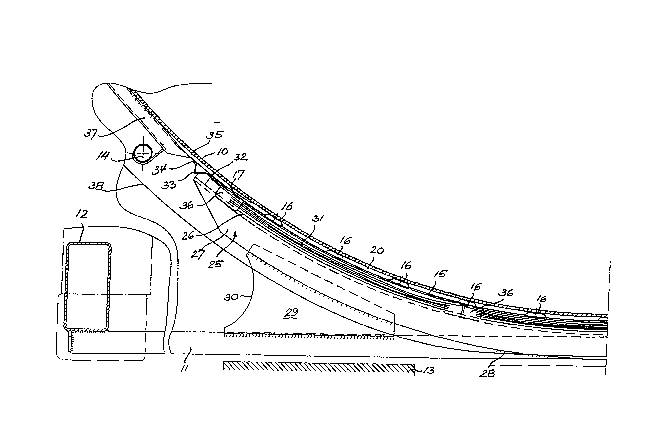
Brief Description of the Drawings
Figure 1 is a section through half of the lower part of
a tank container, taken perpendicularly to the
tank axis.
Figure 2 is an enlarged detail of Figure 1.
Figures 3 and 4 are lateral views, partly in section, of
a portion of the lower tank zone shown in Figure 1.
Detailed Description of Preferred Embodiments
Figure 1 illustrates portions of the tank jacket 10 as
well as of a transverse bar 11 and a longitudinal bar 12,
which bars form part of the lower frame structure of a tank
container. Indicated at 13 is one of the load supporting ar-
eas of a carrier vehicle as they are provided in accordance
with ISO standards to support a container at locations inter-
mediate its corner fittings.
In the lower zone, the tank jacket 10 is surrounded by
an outer shell 15 which extends the entire axial length of
the tank and bears on the tank jacket 10 by a plurality of
frusto-conical socket-type projections 16 formed integrally
in the shell 15, such as by punching. The shell 15 is made
of, e.g., 2 mm sheet steel, with the integral projections 16
serving not only to provide a space with respect to the tank
jacket 10 but also to reinforce of the outer shell 15 itself.
As indicated at 17, the shell 15 is welded along its en-
tire periphery to the jacket 10. Further, at least some, or
even all, of the projections 16 are each provided with a cir-
cular hole 18 in their surfaces of truncation and are con-
nected to the tank jacket 10 by circular welds 19 formed
2~8~97~
along the edges of each hole 18. Thus, the shell 15 cooper-
ates with the tank jacket 10 to forr~ a closed flow chamber 20
through which vapour or some other heating medium is circu-
lated via input and output lines, which are shown at 14. The
flow chamber 20 has a clear height of 6 mm, for example.
The frusto-conical socket-type integral projection 16,
which is shown in Figure 2 on an enlarged scale, is sur-
rounded by an annular spacer 21 which is formed of a stack of
four separate annular discs 22, 23. The spacers 21 are not
shown in Figure 1 for the sake of clarity.
The outer two annular discs 22 of the stack, which are
adjacent to the tank jacket 10 and the shell 15 respectively,
each have a thickness of 1 mm and an outer diameter of 100
mm, whereas the inner two annular discs 23 have a thickness
15 of 2 mm and an outer diameter of 90 mm. The discs 22, 23 are
stamped parts, with the outer two discs 22 being so disposed
that their stamping burrs face each other and the rounded
stamping edges face the jacket 10 and the shell 15, respec-
tively.
The stack of annular discs explained with reference to
Figure 2 has the following advantages over a spacer such as
formed by a single solid disc:
(a) Due to their comparatively small thickness, the in-
dividual discs 22, 23 can adapt themselves exactly
to the local curvatures of the tank jacket 10 and
the outer shell 15.
(b) For the same reason, the individual annular discs
can also follow such variations of curvature as oc-
cur in use due to changes in load, temperature or
the like.
(c) Since the individual discs 22, 23 are not pre-bent,
they can be mounted in any orientation.
(d) Due to their larger outer diameters and their
smaller thicknesses, the outer discs 22 of the stack
adjacent the jacket 10 and the shell 15 result in a
particularly uniform distribution of forces without
7 2~9~1
any abrupt changes in the transmission of forces
from the tank to the saddle structure (described be-
low).
(e) This effect is further irnproved by exploiting the
rounded stamping edges of the outer discs 22.
(f) The inner diameter of the discs 22, 23 may be stag-
gered in accordance with the conical shape of the
projection 16, as shown in Figure 2, so that each of
them provides a maximum surface for the transmission
of forces.
It may be useful during assembly to fix the individual
discs 22, 23, such as by spot welding or gluing, to each
other and to the inner surface of the shell 15 at a single
spot each, without effecting a permanent rigid connection.
The above-described tank, which has its entire lower
zone covered by a continuous outer shell 15 for forming a va-
pour flow chamber 20, is supported by a transverse bar of the
base structure through at least one transverse saddle at an
intermediate location between the two tank ends, one such
transverse bar being shown at 11 in Figures 1, 3 and 4.
The transverse saddle includes a U-profile member 25 the
centre web 26 of which is circularly bent about the tank axis
so as to follow the curvature of the tank. The two legs 27 of
the U-profile member 25 straddle the transverse bar 11 and
are welded directly thereto in the lowermost region of the
tank as shown at 28 in Figures 1, 3 and 4. Above each load
supporting area 13, where the tank is above the transverse
bar due to its curvature, the U-profile member 25 is con-
nected to the transverse bar 11 by a pair of supporting
plates 29 which have their inner surfaces welded to the legs
27 and to the upper edges of the transverse bar 11. At its
edge remote from the lower centre of the tank, each support-
ing plate 29 is provided with a round cut-out 30 to avoid
peak stresses.
A layer of wood 31 having a thickness of approximately
30 mm is inserted between the centre web 26 of the U-profile
2~97~
member 25 and the shell 15. The layer 31 consists of three
separate pieces shells of plywood that are pre-bent in accor-
dance with the curvature of the tank and abut each other in
the circumferential direction.
Further, a band 32 of 2 mm stainless steel is disposed
between the wooden layer 31 and the outer surface of the
shell 15. The band 32 has an outward fold 33 at each of its
circumferential ends. The outermost edge of the band 32 is
welded, as indicated at 34 in Figures 1, 3 and 4, to a circu-
lar reinforcing plate 35 which is in turn welded to the tank
jacket 10. At the locations, where the individual pieces of
the wooden layer 31 terminate, the band 32 is further pro-
vided with lateral, outwardly flanged portions 36 to prevent
the loosely inserted pieces of wood from becoming displaced
in the axial direction of the tank. The folds 33 serve to
compensate differences in length between the tank jacket 10
and the band 32, thus to avoid stress, and further provide an
abutment that prevents the wooden pieces from moving in the
circumferential direction.
As a result of its somewhat soft-plastic structure, the
wooden layer 31 not only effects an insulation between the
outer shell 15 confining the vapour flow chamber 20, and the
U-profile member 25 of the transverse saddle, but also en-
sures a uniform distribution of the forces transmitted be-
tween the tank and the saddle. To this end, the width of the
wooden layer 31 is approximately 150 mm and thus substan-
tially larger than the width of the centre web 26 of the U-
profile member 25, which is 100 mm for example.
The embodiments of Figures 3 and 4 differ from each
other with respect to the (accidental) alignment of the
socket-type projections 16 provided in the outer shell 15
relative to the position of the transverse saddle. In the ar-
rangement of Figure 3, only the projections 16a that are
situated in the centre plane M of the saddle need be provided
with spacers 21 such as shown in Figure 2. For the projec-
tions situated outside the saddle, no such spacers are re-
2~8~971
quired, and are not desired because they reduce the flowchamber.
In the arrangement of Figure ~, no projections 16 are
aligned with the centre plane M of the saddle. In this case,
all, or at least a plurality, of the projections 16b are re-
inforced by spacers 21 according to Figure 2.
In the embodiments described above, the outer shell 15,
which surrounds the lower zone of the tank, extends through
an angle of, e.g. 80 about the tank axis. The rest of the
tank circumference is surrounded by a conventional reinforc-
ing ring 37, the chamfered ends of which are welded to the
reinforcing plates 35, just as are the ends of the band 32,
to avoid peak stresses on the tank jacket 10 and on the shell
15.
Figure 1 also shows an insulation surrounding the entire
tank and having an outer skin 38.