Note : Les descriptions sont présentées dans la langue officielle dans laquelle elles ont été soumises.
20864~8
SELF-ALIGNING CLAMP STRUCTURE
FIELD OF THE 1NV~NL1ON
The present invention relates to an open clamp
structure and more particularly to a self-aligning clamp
structure for softer materials which is provided with a so-
called "Oetiker" ear and which can be manufactured in a cost-
effective manner.
BACKGROUND OF THE I~V~N-L10N
MY prior U.S. Patents 4,315,348 and 4,299,012
described a so-called "Stepless" clamp designed for use with
relatively thin-walled, relatively hard plastic materials.
These prior art clamps have been installed in various
applications, the primary use being a leakage-proof tightening
of axle boots made from "Hytrell" and similar materials and
used in connection with constant velocity joints in the
automotive industry. These prior art clamps proved
commercially immensely successful as evidenced by sales
running into hundreds of millions of such clamps.
2~8~468
Though the use of thermoplastic materials for the
previously mentioned applications has increased over the last
decade, especially in connection with OEM applications, the uses
of materials with a lower Shore hardness such as neoprene and
silicon still play a major role in constant velocity (CV) seals,
as for example, in the after-market. Furthermore, technological
advancements in the formulation of the compounds and the molding
techniques of such thermoplastic materials have resulted in more
malleable compositions so that the stepless feature does not
represent an absolute requisite for all constant velocity
applications.
Additionally, intense cost reduction programs by the
major automotive manufacturers have resulted in the necessity to
provide a product that is more cost-effective than the prior art
clamps with the "Stepless" feature, yet is completely
satisfactory for CV applications with the soft axle boot
materials.
SUMMARY OF THE lNV~ ON
It is therefore a primary object of the present
invention to provide an open clamp structure which assures
compliance with the cost reduction programs, yet assures
completely satisfactory performance in the applications for which
it is intended.
Another object of the present invention resides in an
open self-aligning, low-cost c~amp which permits a reduction in
raw materials as also a reduction in comp~exlty to reduce the
demand for statistical process control.
A further object of the present invention resides in
a self-aligning clamp structure which can be manufactured in
such a manner as to assure improved tool life, thereby
reducing the down time for repair and maintenance which in
turn permits a reduction of costs.
Still a further object of the present invention
resides in a clamp of the type described above which permits
improved productivity.
Still another object of the present invention
resides in a self-aligning clamp of the type described above
which offers design attributes superior to other "generic"
clamp products available in the market.
The underlying problems are solved according to the
present invention by a clamp which includes a simplified
mechanical connection and a so-called plastically deformable
"Oetiker" ear with a reinforcement permitting tightening of
the clamp with conventional tools, whereby the various parts
are so arranged as to permit a reduction in length of the
clamping band material required for the clamp of a given size.
According to another feature of the present
invention, the configuration of the inner band end according
to this invention provides a distinct advantage over
conventional end configurations of prior art clamps by
lessening the danger of damage to the hose.
More specifically, in one aspect the invention
consists of a self-aligning, cost-effective clamp structure,
, .~
2~6468
comprising clamping band means having inner and outer band
portions of full band width and having center areas, con-
necting means for connecting overlapping inner and outer band
portions, tightening means including at least one plastically
deformable ear means for tightening the clamp about an object
to be fastened thereby, and guide means for guiding over-
lapping inner and outer band portions during tightening of the
clamp structure, said connecting means including only two hook
means outwardly extending from the inner band portion and
operable to engage in apertures provided therefor in the outer
band portion, one of said hook means being a tab-like member
pressed out of the clamping band in a transversely extending
plane intersecting the clamping band in the transverse
direction thereof, and the other hook means being a cold-
deformed support hook, the plastically deformable ear means
including two generally outwardly extending leg portions
interconnected by a bridging portion, and the guide means
including a narrow longitudinal slot in the center area of the
outer band portion and a tab-like member pressed out of the
full band width inner band portion near its end in such a
manner that it extends outwardly in the longitudinal direction
and can slidably extend within said slot whereby the presence
of only two hook means and the location of the tab-like member
permit a reduction in the clamping band material required for
the clamp structure.
The invention also consists of a self-aligning,
cost-effective clamp structure, comprising clamping band means
-3a-
2086468
having full band width inner and outer band portions with
center areas, connecting means for connecting overlapping
inner and outer band portions, tightening means including at
least one plastically deformable ear means for tightening the
clamp about a hose-like object to be fastened thereby, and
guide means for guiding overlapping inner and outer band
portions during tightening of the clamp structure, said
connecting means including at most two hook means outwardly
extending from the inner band portion and operable to engage
in apertures provided therefor in the outer band portion, the
plastically deformable ear means including two generally
outwardly extending leg portions interconnected by a bridging
portion, the guide means including a narrow longitudinal slot
in the center area of the outer band portion and a tab-like
member pressed out of the center area of the full band width
inner band end portion in such a manner that it extends in the
longitudinal direction and can slidably extend within said
slot, and means including end surface means at the free end of
the inner band portion to minimize damage to the underlying
hose-like object during relative sliding movement of the inner
band portion in the course of a tightening operation whereby
the presence of at most two hook means and the location of the
tab-like member permit a reduction in the clamping band
material required for the clamp structure.
-3b-
~ r
2086A68
.
Guide arrangements for open clamps are known as such.
For example, in my prior German DE-AS 24 58 175, a tongue-like
extension at the end of the inner band portion is intended to be
guided within a guide slot in the outer band portion. My prior
U.S. Patent 4,083,086 describes an upwardly bent tongue at the
inner band end which is guided in a slot in the outer band
portion. The European Patent EP 0 236 217 describes an outwardly
directed T-shaped bent-up part adapted to cooperate with a
longitudinal slot. However, whereas the slots in these prior art
patents require a certain width, the guide arrangement in
accordance with the present invention requires only a narrow slot
for engagement by a small outwardly bent tab member extending in
the longitudinal direction in the full width end area of the
inner band portion. Finally, the German Gebrauchsmuster G 90 15
003.1 discloses a bent-up guide member along the edge of a
lateral tongue-like extension of the clamping band adapted to
engage in a relatively narrower slot. However, the location of
the bent-up guide member along the edge at the end of the tongue-
like extension entails other problems in the reliability of
operation.
A reinforcing depression of substantially rectangular
configuration as viewed in plan view is described in my copending
U.S. application Serial No. 06/922,408, filed October 23, 1986,
entitled "Deformable Ear For clamps"; which is a continuation
application of my then copending application Serial No.
06/622,764 filed on June 20, 1984 as also in my copending
29864~
- pplication Serial No. 07/629,716, filed December 18, 1990
entitled "Reinforced Ear Structure For Clamps." The clamp,
including its reinforcing depression, has been further fine-tuned
to assure reliable operation of the clamp for its intended
purpose.
BRIEF DESCRIPTION OF THE DRAWING
These and other objects, features and advantages of
the present invention will become more apparent from the following
description when taken in connection with the accompanying drawing
which shows, for purposes of illustration only, one embodiment in
accordance with the present invention, and wherein:
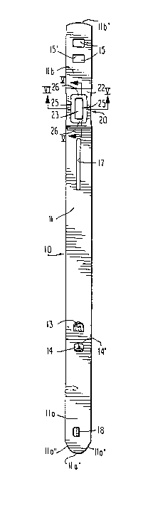
Figure 1 is a plan view on the punched-out blank of a
self-aligning clamp structure in accordance with the present
invention before deformation into rounded form;
Figure 2 is a side elevational view of the clamp
structure of Figure 1;
Figure 3 is a partial perspective view showing the
clamp structure of Figures 1 and 2 after being deformed into round
shape and with the parts thereof in pre-assembled position prior
to tightening;
Figure 4 is a partial perspective view, similar to
Figure 3, showing the various parts in their position after
plastic deformation of the ear;
Figure 5 is a cross-sectional view taken along line
V-v of Figure 1; and
Figure 6 is a cross-sectional view taken along line
IV-IV of Eigure 1.
DETAILED DESCRIPTION OF THE DRAWINGS
Referring now to the drawing wherein like reference
numerals are used throughout the various view to designate like
-5-
, .
- 2û86468
parts, the self-aligning clamp structure in accordance with the
present invention which is generally designated by reference
numeral 10 includes a clamping band 11 made, for example, from
galvanized steel or stainless steel clamping band material. The
clamping band 11 includes inner and outer end portions lla and
llb at opposite ends thereof which will overlap when the open
clamp is bent into its intended circular shape. The mechanical
connection for connecting overlapping band portions includes a
single hook-li~e guide member 13 and a single cold-deformed
support member 14 for engagement in rectangular apertures 15
provided in the outer band end portion llb. The guide member 13
is thereby in the form of a tab-like member bent out of the band
material about an axis extending transversely to the longitudinal
direction so that the free end of the guide member extends
obliquely outwardly in a direction opposite the free end of the
inner band portion lla and the main engaging surface also extends
in a plane intersecting the clamping band in the transverse
direction. The hook-like guide member 13 may thereby be slightly
bent at its outer end as shown in Figure 1 to facilitate
preassembly (Figure 3). After such pre-assembly, the guide
hook 13 may be bent down toward the clamping band to further
secure the clamp structure in its preassembled condition. The
support member 14 may be a cold-deformed support hook, for
example, as disclosed in my prior U.S. Patent 4,299,012 with an
abutment surface 14' (Figure 1) extending transversely and with
2086468
the remainder of the support member 14 integral with the clamping
band over substantially the rest of its contour.
The end of the inner band portion lla is of more or
less parabolic shape formed by the rounded end surface lla' and
the lateral surfaces lla''. The parabola shape of this invention
entails the distinct advantage over the commercially available
prior art straight or radius-end configurations preventing or at
least minimizing the unavoidable damage of the less rigid hose
materials by the inner end of the prior art clamps during closing
movement of the clamp produced by plastic deformation of the ear
and during the resulting reduction in diametric dimension. The
parabolic shape in accordance with the present invention
significantly improves this condition as it allows the material
of the hose or axle boot to flow around the geometrical shape,
thereby reducing the plunger action of a straight edge.
The radius in the curved end surface llb' of the
opposite end portion llb results in an increase in die life due
to the absence of intermittent cuts, distinctive of prior art
designs. The radius configuration llb' thereby also reduces the
possibility of sharp corners which represented the significant
aspect of the chamfers in the prior art clamp designs.
A significant detrimental feature of many commercially
available crimp-style clamps is the inability of self-alignment.
If the assembly tool is not located precisely at 90 to the edge
of the clamping band, the underlying end of the band protrudes
from the edge of the clamp, resulting in deviations of the
2086468
intended circumferential configuration. The self-aligning
clamp in accordance with the present invention overcomes this
drawback by incorporating a narrow slot 17 in the center area
of the outer band portion. A protruding tab-like member 18
which is punched-out and bent at right angle with respect to
the plane of the clamping band so as to extend outwardly
substantially in the longitudinal center plane, is adapted to
engage in the narrow slot 17 and thereby guides the clamp
during the closing operation. The slot 17 can thereby be made
relatively narrow, for example, may have a width of only about
1.2 mm as it only needs to permit the tab-like member having a
thickness corresponding to the thickness of the clamping band
to extend therethrough. This guidance arrangement assures a
symmetrical and uniform closure of the clamp. At the same
time, the narrow slot 17 does not materially weaken the
clamping band and can be located close enough to the plas-
tically deformable so-called "Oetiker" ear generally desig-
nated by reference numeral 20 as to reduce the amount of band
material required for a given clamp size. The "Oetiker" ear
20 includes two generally outwardly extending leg portions 21
and 21' interconnecting the ear with the overlapping outer
band portion llb. The generally outwardly extending leg
portions 21 and 21' are interconnected by a bridging portion
22 extending in the longitudinal direction of the clamp. The
bridging portion 22 is thereby provided with reinforcing means
in the form of a shallow depression 23 which may be constructed
as described in my aforementioned copending applications, the
subject matter of which is incorporated herein
-8-
2086468
by reference. To achieve the desired holding ability of theear 20 for the intended applications, the depression 23 of this
invention is thereby of generally rectangular configuration with
the longitudinal sides and the transverse sides thereof extending
at least approximately parallel to one another. The corners
between the longitudinal and transverse sides of the generally
rectangular depression 23 are preferably rounded off utilizing
small radii of curvature which may be constant or vary in a given
area. These radii of curvature are chosen in such a manner as to
minimize impacting on the rectangular configuration of the
depression 23 yet avoid problems that might be caused by sharp
connecting corners. The bottom 24 (Figure 2) of the shallow
reinforcing depression 23 is thereby generally flat in both the
longitudinal and transverse directions. However, the bottom 24
may also have a slight concave curvature in the longitudinal
direction with a radius of curvature of about 5 mm. The
bottom 24 is interconnected with the remaining non-depressed
parts of the bridging portion surrounding the depression 23 by
way of longitudinally extending connecting portions 25 and
transversely extending connecting portions 26. Again, to avoid
sharp corners, the transition of the longitudinally extending
connecting portions 25 and of the transversely extending
connecting portions 26 with the bottom 24 and the remaining non-
depressed parts of the bridging portion 23, are rounded-off
utilizing small radii of curvature which may be constant or may
vary in a given area. These radii of curvature are thereby
_g _
2086~68
-
chosen so as to impact as little as possible on the general
configurations of the area of the bottom 24 and the remaining
non-depressed parts of the bridging portion 22. In a preferred
embodiment, these radii of curvature are about 2 mm. The angle
a subtended by the longitudinally and transversely extending
connecting portions 25 and 26 with the plane containing the
bottom 24 and the remaining non-depressed parts of the bridging
portion, is between about 90 and about 110, preferably about
90 to ~8. The angles formed by the longitudinal connecting
portions 25 and the transverse connecting portions 26 may be
substantially identical or may also be different having values
falling within the above-indicated ranges. The area of the
reinforcing depression, measured in the plane of the bridging
portion 22 is about 30% to about 55% of the total area of the
bridging portion 22 and is preferably about 40% to 45% of the
total area of the bridging portion in its non-reinforced
condition, i.e., before the depression is made. The reinforcing
depression 23 thus resembles a shallow pan-shaped configuration
as found, for example, with Pyrex-type cooking pans of
rectangular configuration and relatively shallow depth as
compared to other cooking pans.
By omitting the tongue-like extension of the inner band
portion and the tongue-receiving channel in the outer band
portion which were necessary to achieve the stepless feature in
my prior U.S. Patent 4,299,012, the dimensional controls,
previously necessary to assure compliance with the design of the
--10--
208~468
clamp in accordance with my prior U.S. Patent 4,299,012, could be
dramatically reduced. This omission is quite acceptable as the
intended application of the clamp in accordance with the present
invention compensates for any irregularities along the inner
circumference.
In addition to the particular configuration of the
rounded end llb' and of the parabolically shaped end lla', lla''
in the outer and inner band portions llb and lla, improved tool
life which reduces "down time" for repair and maintenance and
therewith reduces manufacturing costs, is also achieved by the
particular configuration of the tab-like member 18 which has
rounded corners 18a and 18b realized by the particular cut in the
clamping band shown in Figure 1. A reduction in necessary band
material is attainable by omitting a third hook-like connecting
member and the necessary aperture which would be required
therefor. Additionally, by locating the tab-like member 18 in
the end area of the band portion lla where the latter commences
to converge into parabolic form and by extending the slot 17
close to the leg portion 21', which is made possible by the
narrow width for this slot, clamping band material can be further
economized. As these clamps are expected to be sold by the
millions, even a few millimeters in required band length affect
the cost thereof.
O P E R A T I O N
To install the clamp over the object to be fastened
thereby such as a hose or axle boot, the clamp is preformed into
20~6~68
circular shape so that the hook-like connecting members 12 and 13
can engage in apertures 15. This preforming may take place at
the manufacturer of the clamps in which case the tab-like
member 13 may also be additionally bent down after preassembly to
increase the holding ability of the clamp in its preassembled
condition. Additionally or in the alternative, the tab-like
member 18 can also be bent over at its outwardly protruding end
to thereby preclude its undesired escape from slot 17. In the
alternative, the clamps can be supplied in their elongated
condition as shown in Figures 1 and 2 which greatly reduces the
shipping costs and can then be predeformed at the place of
installation of the clamp, for example, by the use of a machine
as disclosed in my prior U.S. Patent 4,425,781 or in my prior
U.S. Patent 4,633,698. The preformed and preassembled clamp
(Figure 3) can then be axially mounted over the object to be
fastened. In the alternative, it can also be radially mounted
over the object to be fastened by slightly reopening the clamp,
slipping it radially over the object to be fastened and then
engaging hook-like connecting members 12 and 13 in apertures 15.
To tighten the clamp, the plastically deformable ear 20 is then
deformed by the use of a conventional pincer-like tools. As the
ear 20 is plastically deformed, the tab-like guide member 13 will
guide the inner and outer band portions lla and llb toward one
another until the support hook 14 is able to engage with its
abutment surface a~ the transversely extending end 15' of the
aperture I5. The resulting plastically deformed ear of more or
-12-
2086468
less omega shape is shown in Figure 4. During the tightening of
the clamp by plastic deformation of the ear 20, the overlapping
band portions are securely guided relative to one another by the
tab member 18 guided within slot 17.
The clamp in accordance with the present invention
offers significant advantages as regards requirements of raw
material, tool life and productivity, all of which can be
significantly improved by the present invention. Additionally,
the demand for statistical process control can be significantly
reduced by a reduction of the complexity of the clamp itself.
All of these advantages can be attained by the clamp in
accordance with the present invention which represents a
combination of specific features that contribute to the overall
performance of the clamp. Moreover, though the clamp of the
present invention omits features previously found in so-called
"Stepless" clamps, it maintains a high reliability in operation
for the intended applications. Additionally, the self-aligning
clamp in accordance with the present invention will satisfy the
requirements for greater cost effectiveness without impairing its
adequacy in operation.
While I have shown and described only one embodiment in
accordance with the present invention, it is understood that the
same is not limited thereto but is susceptible of numerous
changes and modifications as known to those skilled in the art.
For example, in lieu of guide hook 13, a combined guide and
support hook as disclosed in my prior U.S. Patent 4,622,720 may
-13-
2086468
be used. Such a single or two combined guide and support hooks
may also be used in some applications for the two hooks 13 and 14
as disclosed herein. I therefore do not wish to be limited to
the details shown and described herein but intend to cover all
such changes and modifications as are encompassed by the scope of
the appended claims.
-14-